Kuulaa PD+QC 36W KL-CD06
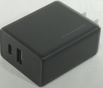
Official specifications:
- Input: 100-240V 50/60Hz
- Output USB-C: 3.6V-6.5V 3A, 6.5V-9V 2A, 9V-12V 1.5A
- Output QC: 3.6V-6.5V 3A, 6.5V-9V 2A, 9V-12V 1.5A
I got it from Aliexpress: kuulaa Official Store
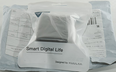
It arrived in a Kuulaa plastic bag inside a plastic envelope.
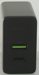
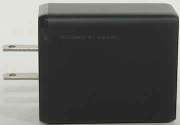
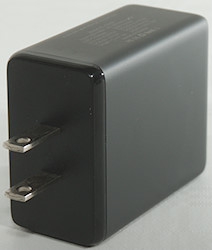
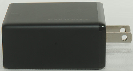
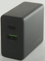
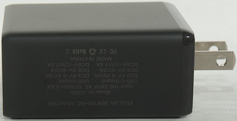
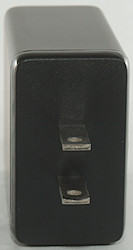
Measurements
- Power consumption when idle is 0.32 Watt
- USB-C PD outputs 5V 3A, 9V 2A, 12V 1.5A
- USB-C PD output is also coded with: QC3, Huawei-FCP, Samsung-AFC
- Minimum QC3 voltage is 4.2V
- QC3 output is coded as Apple 2.4A, DCP, QC3, Huawei-FCP
- GND is common for the two USB outputs
- Weight 66.1g
- Size: 74 x 48 x 28.3mm
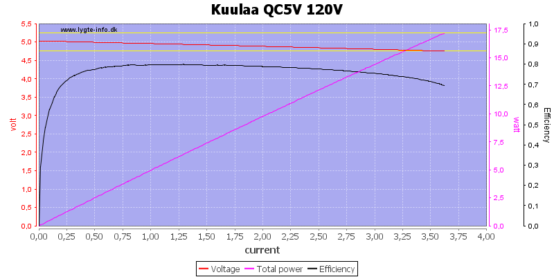
It can easily deliver the rated 3A on the QC output.
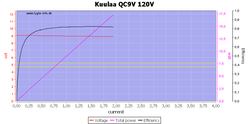
And nearly the rated 2A for 9V
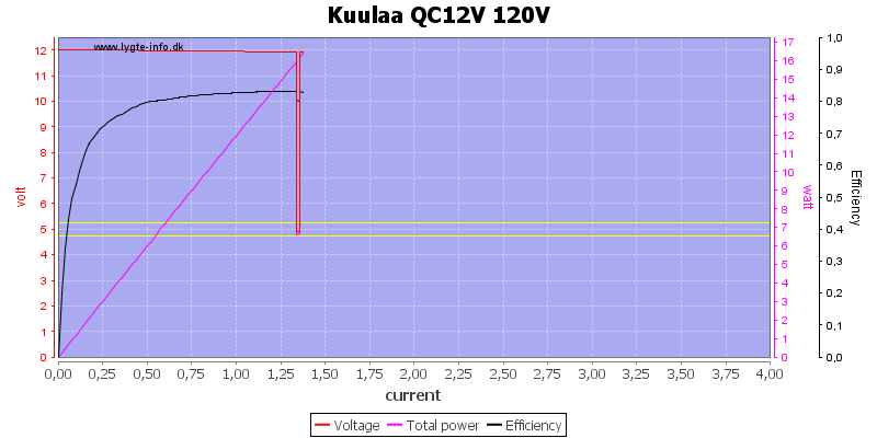
At 12V it can only deliver about 1.3A and not the rated 1.5A
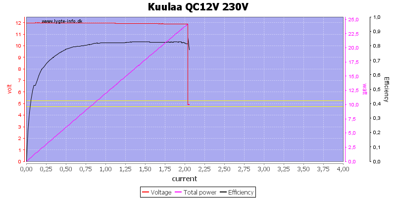
Using a 230VAC supply it can easily live up to its rating.
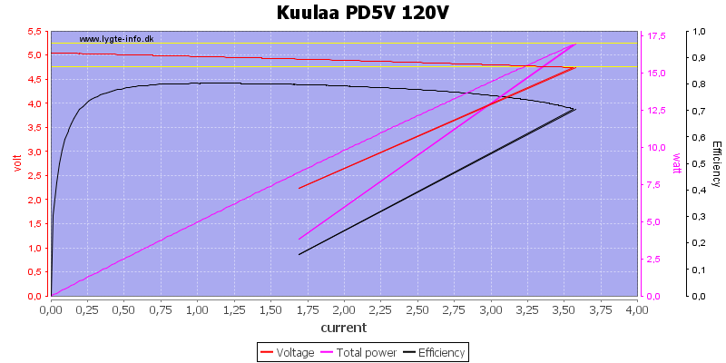
The PD output can deliver 3.5A at 5V
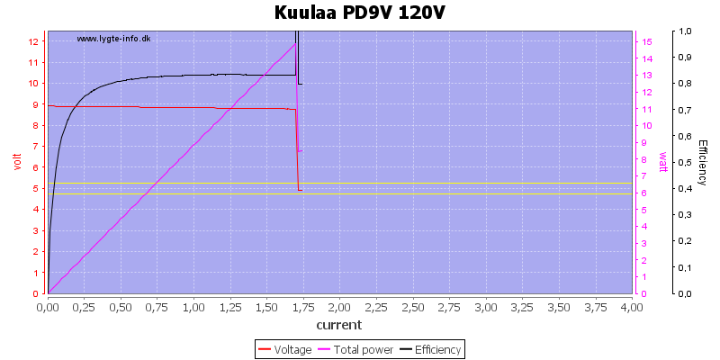
At 9V it is slightly below the rated 2A.
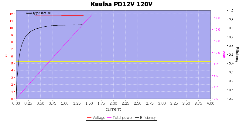
At 12V it is again below the rating.
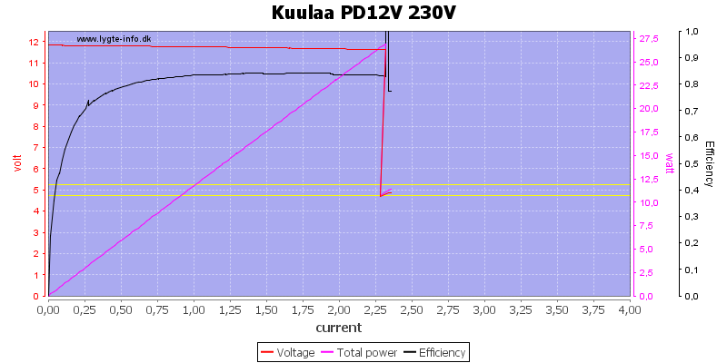
Using 230VAC it can easily live up to its rating.
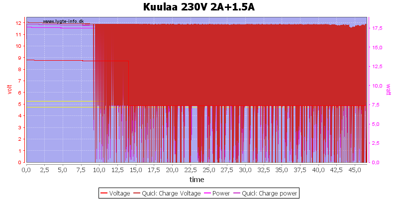
I did the one hour run at 230VAC using 9V and 12V output, this only worked for about 10 minutes.
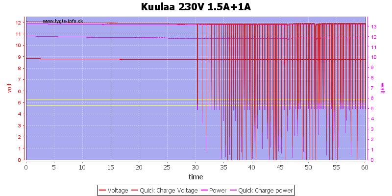
Reducing the current some improved the runtime to 20minutes
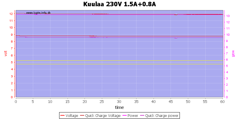
After reducing the current a bit more I could run it for one hour.
The temperature photos below are taken between 30 minutes and 60 minutes into the one hour test.
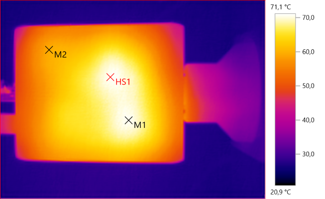
M1: 70.6°C, M2: 59.3°C, HS1: 71.1°C
The two hot spots (HS1 & M1) are the two switcher chips.
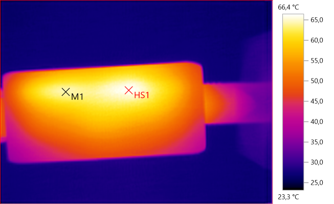
M1: 64.2°C, HS1: 66.4°C
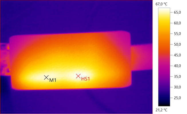
M1: 66.0°C, HS1: 67.0°C
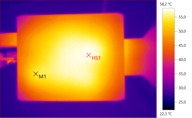
M1: 54.0°C, HS1: 58.2°C
Here the hot area is partially due to the transformers.
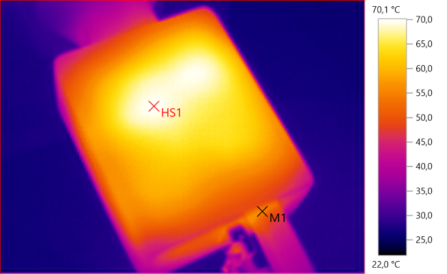
M1: 55.1°C, HS1: 70.1°C

At 0.5A the noise is 97mV rms and 1121mVpp.

At 1A the noise is 47mV rms and 917mVpp.

At 2.5A the noise is 79mV rms and 917mVpp.
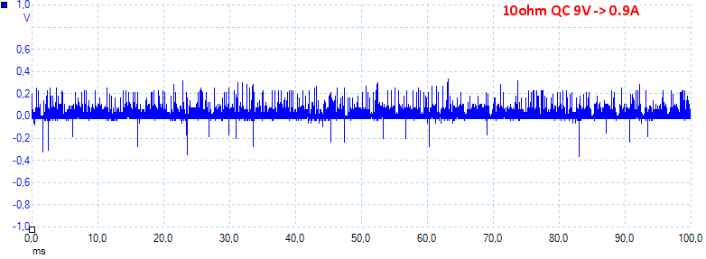
At 9V 0.9A the noise is 69mV rms and 1138mVpp.
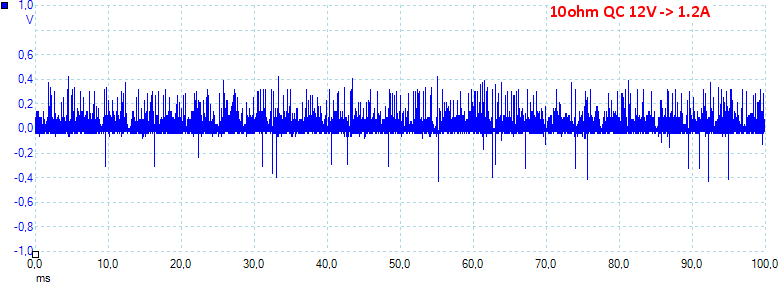
At 12V 1.2A the noise is 68mV rms and 1121mVpp.
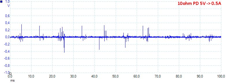
At 5V 0,5A the noise is 24mV rms and 953mVpp.
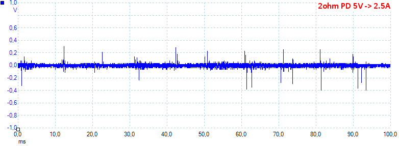
At 5V 2.5A the noise is 76mV rms and 970mVpp.
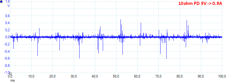
At 9V 0.9A the noise is 32mV rms and 1200mVpp.
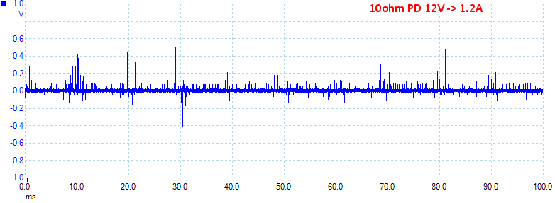
At 12V 1.2A the noise is 37mV rms and 1306mVpp. There is a lot of peaks in the noise, probably common mode noise from bad mains filtering.
Tear down
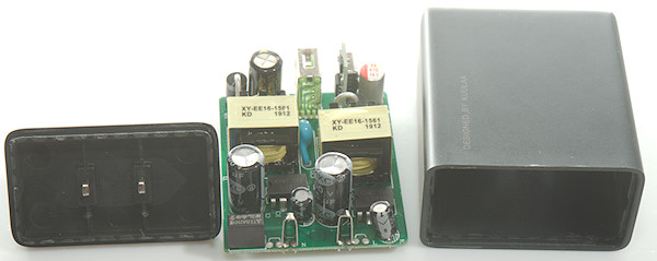
I put some pressure on the enclosure with a vice and could then break the bottom away with my fingers.
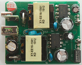
The circuit is two nearly identical switch mode supplies, only difference is the output capacitor that is 1000uF for the QC and 470uF for PD. The only common part between the two are the input fuse (F1)
The QC controller (FT41NR) is placed next to the USB connector, the PD controller on a small circuit board.
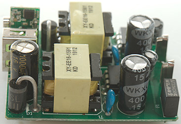
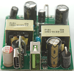
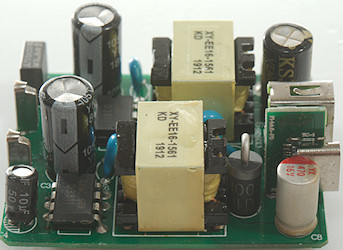
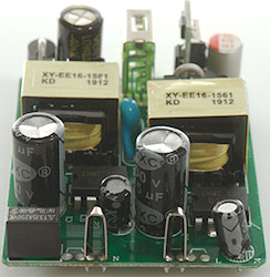
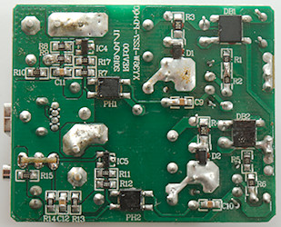
On this side is the bridge rectifiers (DB1 & DB2), one for each switcher, the opto feedback (PH1 & PH2) and the references (IC4 & IC5: 431).
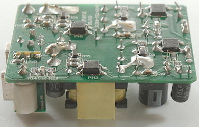

The PD controller has a PD chip (U1: FP6606C) and a MOS transistor to switch the output on/off.

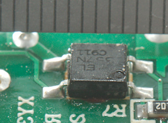
The distance across the opto coupler is only 4.5mm, this is way below the requirements.
Testing with 2830 volt and 4242 volt between mains and low volt side, did not show any safety problems.
Conclusion
At 120VAC it cannot deliver rated power and it can never deliver rated power for longer time. The supply is also a bit limited with PD, where the maximum is 12V, not 20V.
The isolation distance between mains and low volt side is on the low side, especially for 230VAC.
Notes
Index of all tested USB power supplies/chargers
Read more about how I test USB power supplies/charger
How does a usb charger work?


