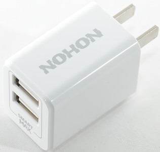
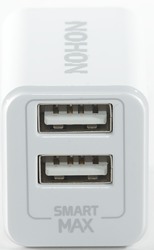
Nohon 3C double usb charger
Official specifications:
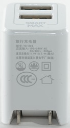
- Input: 100-240VAC 50/60Hz
- Output: 5.0V 2.4A
- Model number: TC-029
I got it from a reader
Measurements
- Power consumption when idle is 0.06 watt
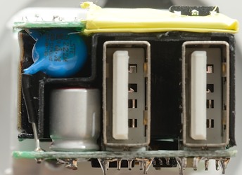
- Usb outputs is auto detect with Apple 2.4A as maximum.
- Usb outputs are in parallel
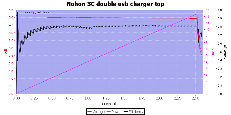
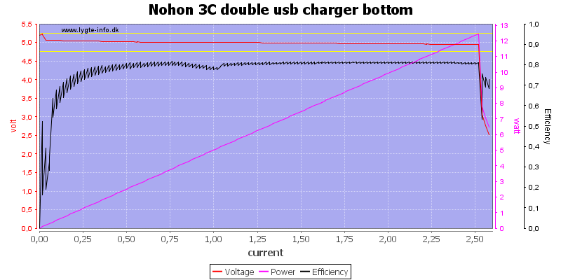
Each output can deliver 2.5A, very nice overload protection for a 2.4A output.
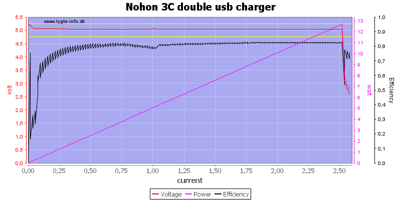
The total power is also 2.5A, i.e. this charger can only handle one high current device at a time.
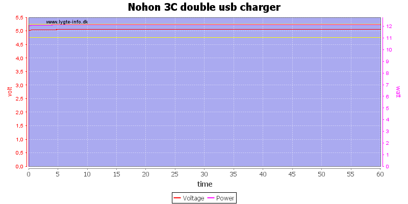
I could draw 2.4A for 1 hour without any problems.
The temperature photos below are taken between 30 minutes and 60 minutes into the one hour test.
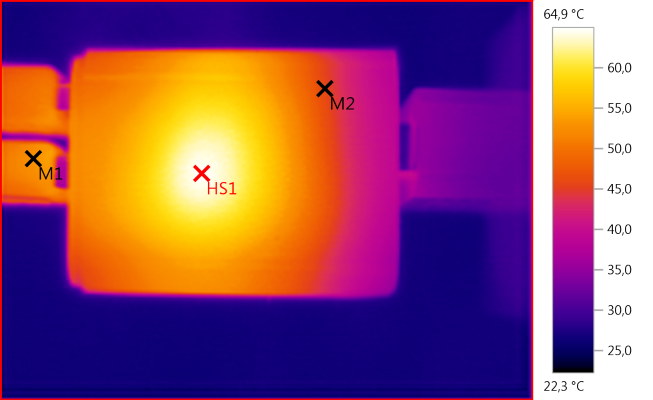
M1: 52,9°C, M2: 45,8°C, HS1: 64,9°C
HS1 is the rectifier diode.
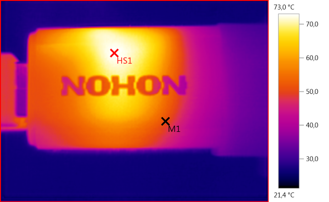
M1: 50,9°C, HS1: 73,0°C
HS1 must be the switcher transistor.
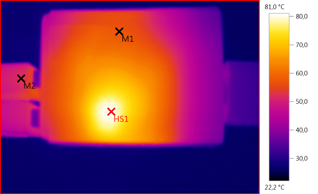
M1: 57,3°C, M2: 52,3°C, HS1: 81,0°C
HS1 must be the switcher transistor.
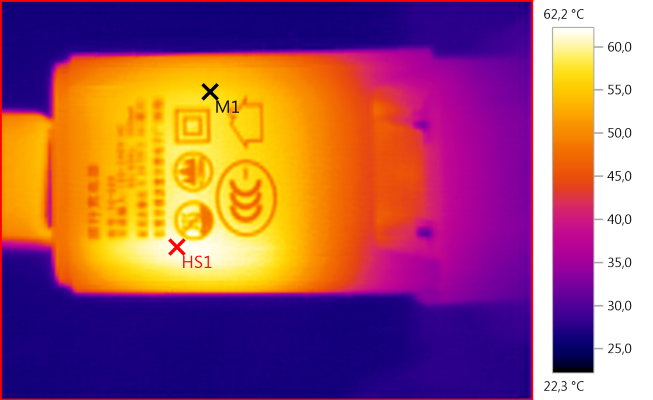
M1: 56,6°C, HS1: 62,2°C
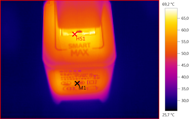
M1: 51,7°C, HS1: 69,2°C
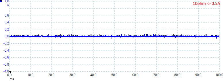
Noise at 0.5A load is 14mV rms and 170mVpp
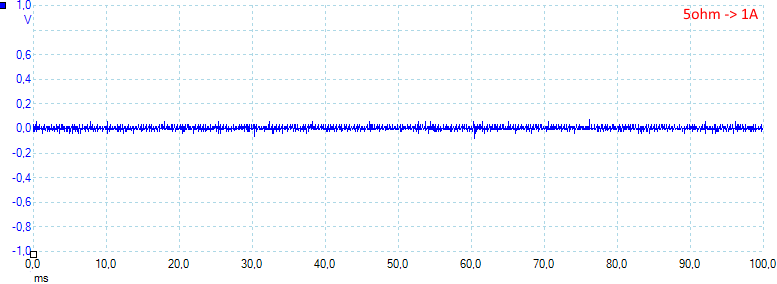
Noise at 1A load is 14mV rms and 154mVpp
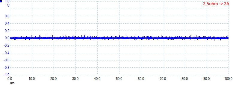
Noise at 2A load is 19mV rms and 177mVpp
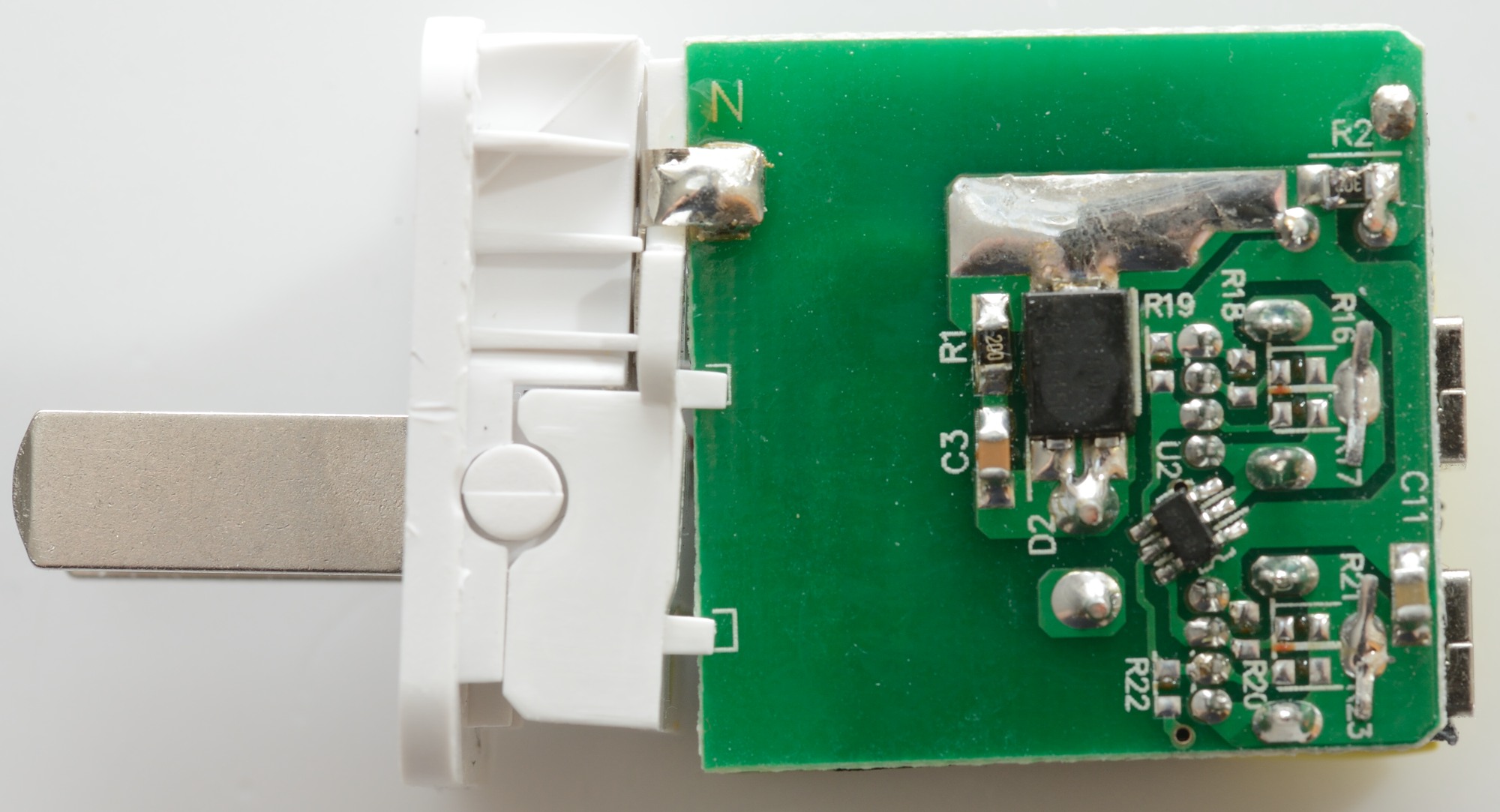
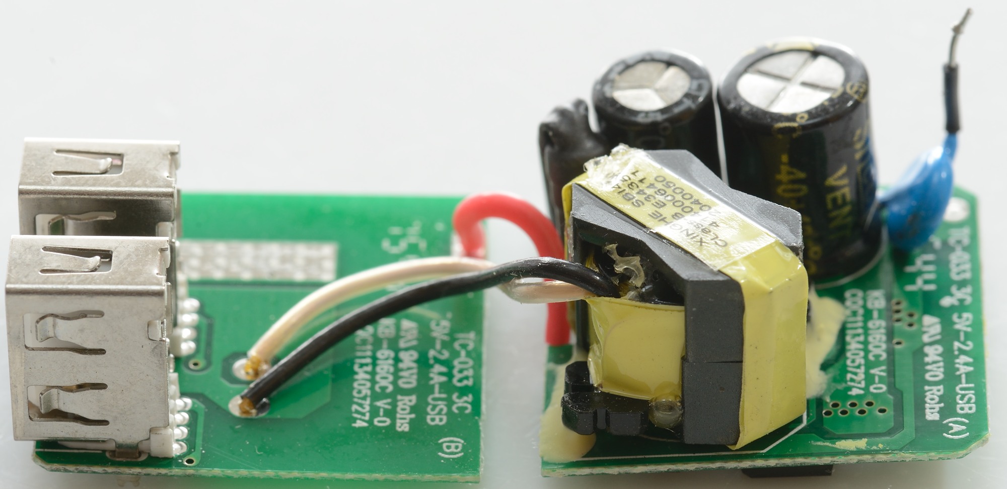
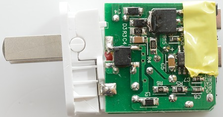
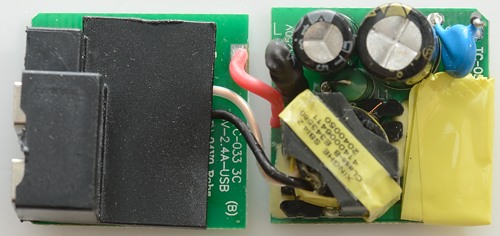
Tear down

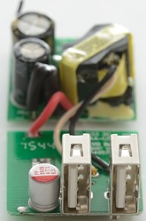
With my vice I could press it open. This is two circuit boards against each other.

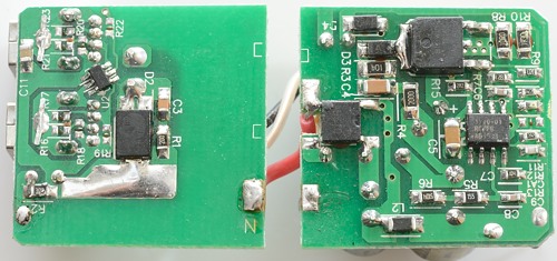
On this circuit board there is a large rectifier diode (D2) and a usb auto coding chip (U2).
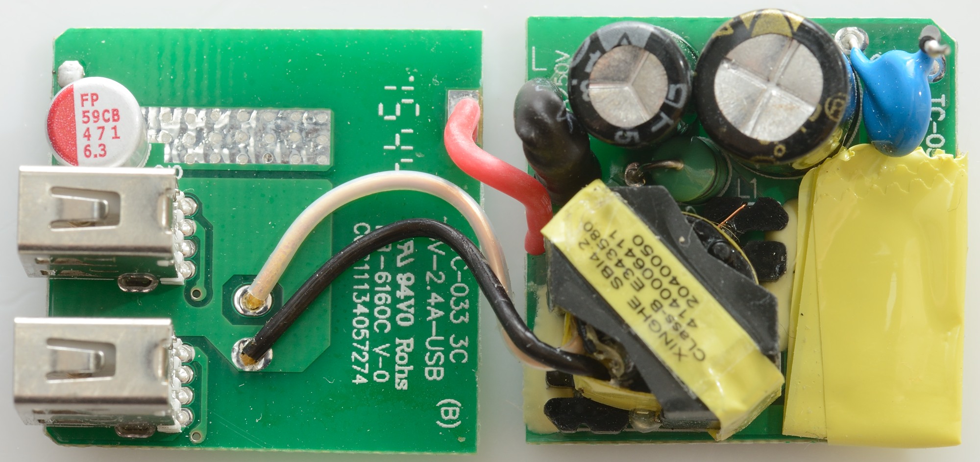
The other circuit board is the mains side, it has a bridge rectifier, a switching transistor and a switch controller IC (Partial hidden under the yellow tape).
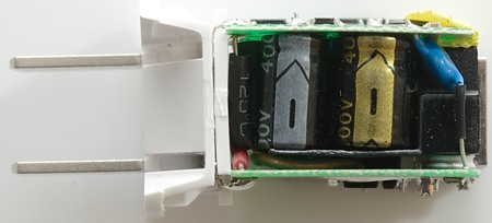
The safety cap is mounted between the two circuit boards.
Notice the black plastic shield, it is used to isolate between mains and low volt side.
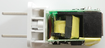
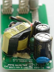
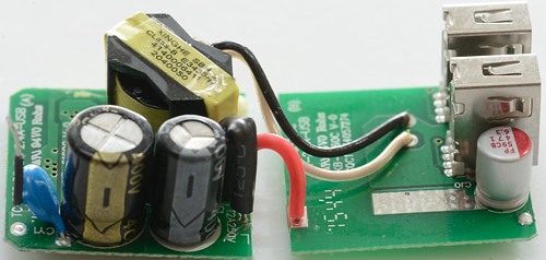
Transformer and plastic shield.
Again the safety capacitor can be seen and the plastic shield.
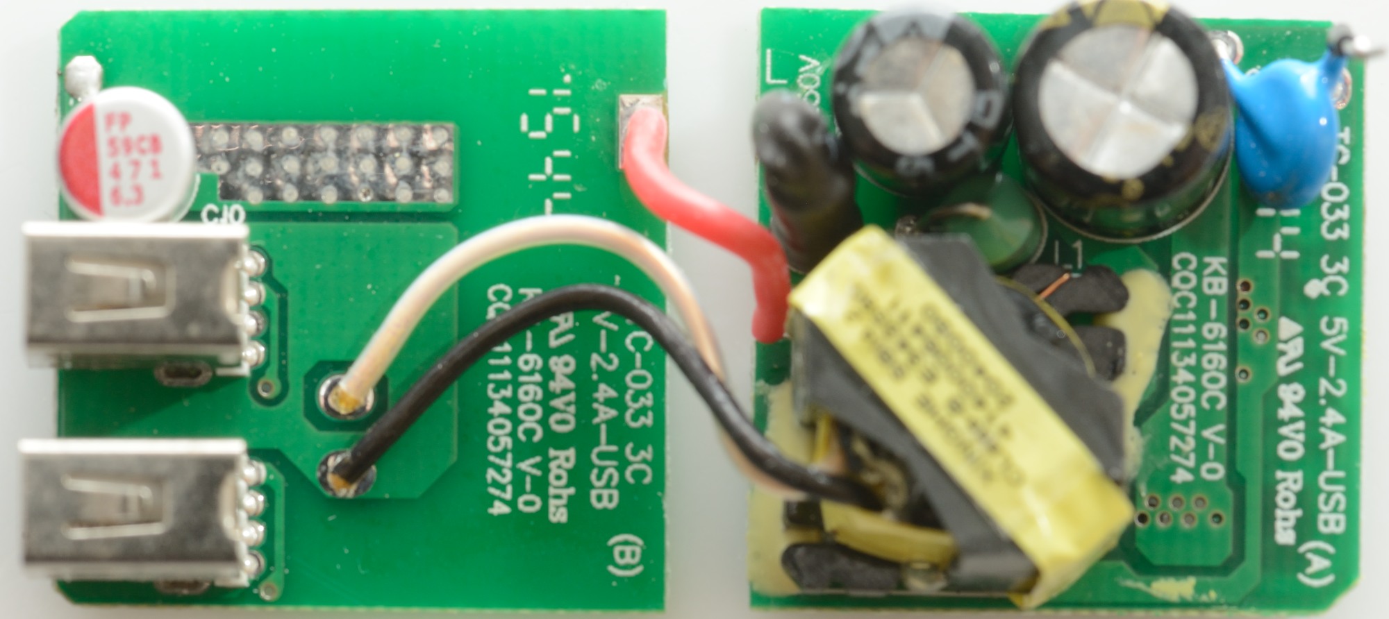
Unsoldering the circuits boards from the mains plug and unsoldering one of the safety capacitors connections, makes it possible to open the two circuit boards.
There is a fuse and a inductor on the mains circuit board.

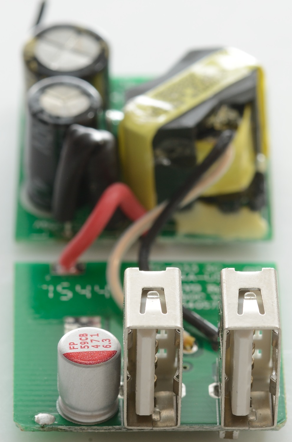
Here it is without the plastic shield, notice the two output wires from the transformer with thick isolation.

Here I also removed the thick layer of isolation tape.
Another view on this side of the circuit boards.
Here the fuse can be seen near "L" connection, it is hidden in black heat shrink.

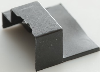
The plastic shield.
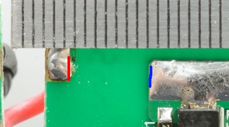
Good isolation distance here.
The distance between conductive parts on mains and low volt side must be at leat 4mm in air. Due to the complex construction it is difficult to see if it maintains it everywhere, but I believe it does.
Testing with 2500 volt and 5000 volt between mains and low volt side, did not show any safety problems.
Conclusion
This compact usb power supply looks good, stable output voltage, auto coding, fairly low noise and good safety, but it can only handle one power hungry phone at a time.
Notes
I got the usb power supply from a reader for review.
Index of all tested USB power supplies/chargers
Read more about how I test USB power supplies/charger