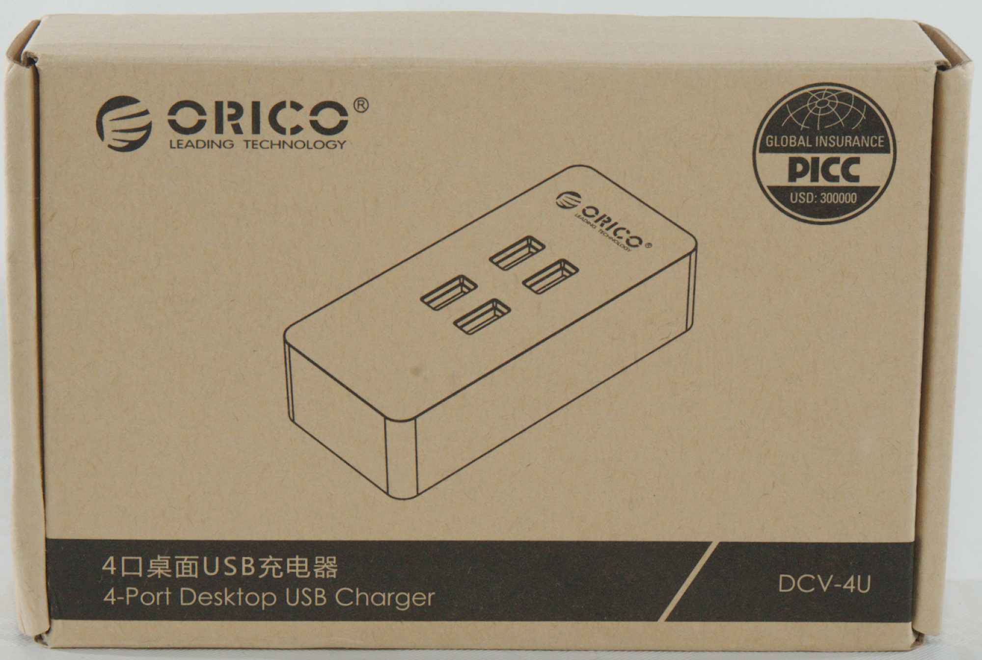
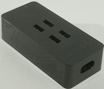
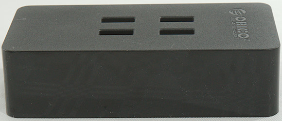
Orico 4 port desktop charger DCV-4U
Official specifications:
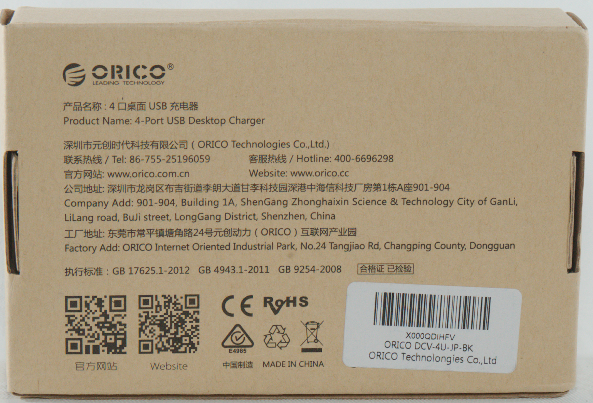
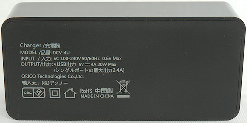
- Model: ORICO DCV-4U
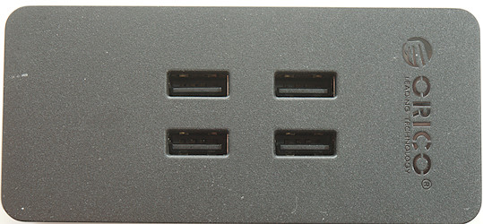
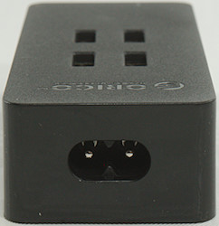
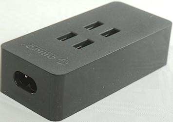
- Ports: 4 USB charging ports
- Dimensions: 98 x 45 x 26
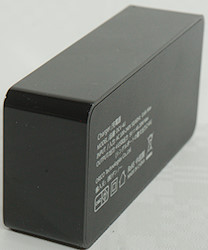
- Input: 100-240V 50/60Hz
- Output: 5V 2.4A each port
- Max. Output: 5V 4A 20W
I got it from aliexpress dealer: Orico Official Store

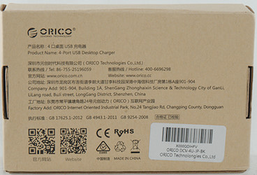
I got it in a brown cardboard box.
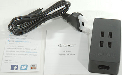
It contained the charger, a mains cable and a instruction sheet.
Measurements
- USB outputs are auto code with Apple 2.4A, Samsung and DCP
- USB outputs are in parallel.
- Power consumption when idle is 0.12 Watt
- Mains cable resistance is 2x31mOhm (Good cable)
- Weight: 110.6g
- Size: 99.4 x 45.9 x 26.6mm
There is no individual port protection on the outputs.
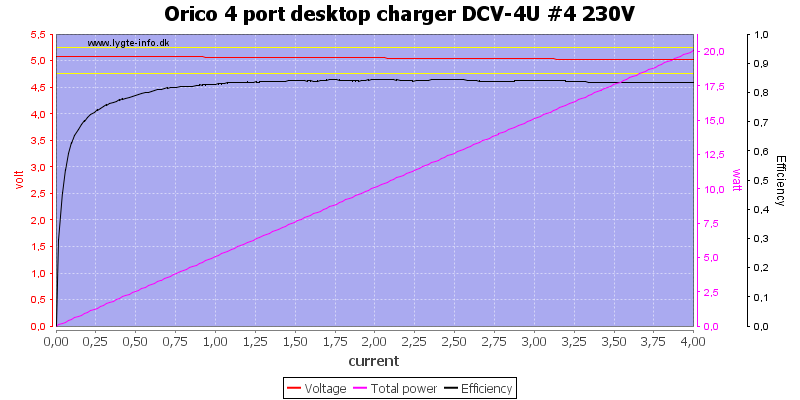
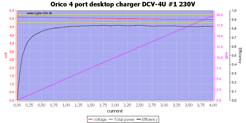
All outputs looks similar.

Running all in parallel I could draw 4.5A before the overload protection trips.
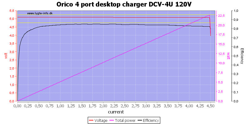
It is the same at 120VAC
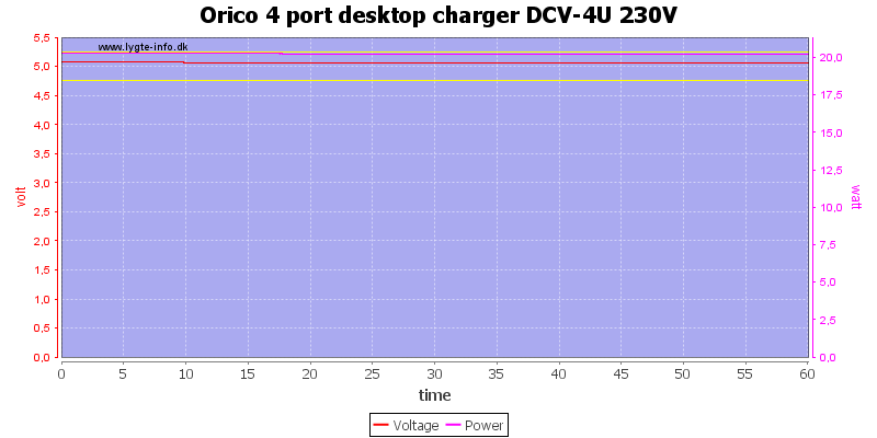
For a load test I used 4A load for one hour, it worked fine.
The temperature photos below are taken between 30 minutes and 60 minutes into the one hour test.
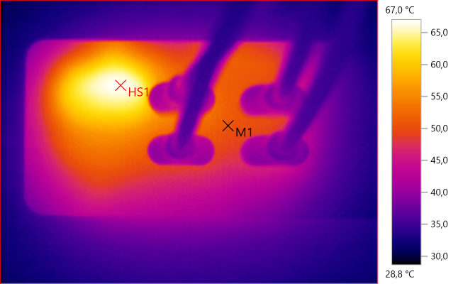
M1: 50.7°C, HS1: 67.0°C
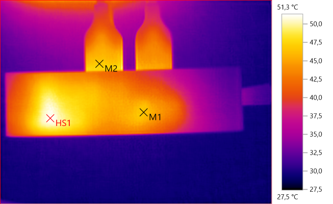
M1: 46.4°C, M2: 46.9°C, HS1: 51.3°C
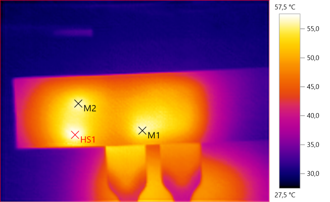
M1: 56.0°C, M2: 56.0°C, HS1: 57.5°C
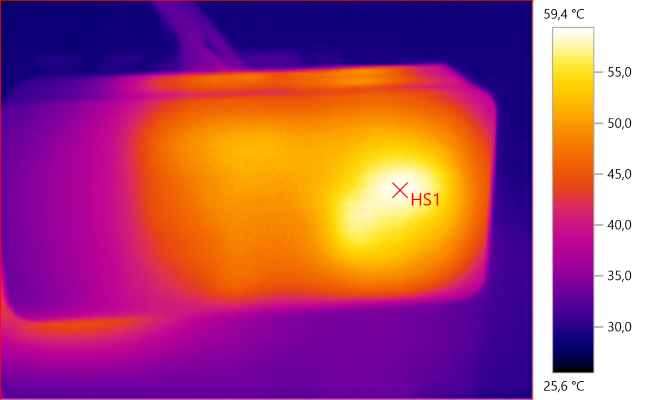
HS1: 59.4°C
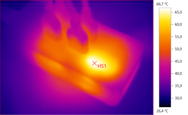
HS1: 66.7°C
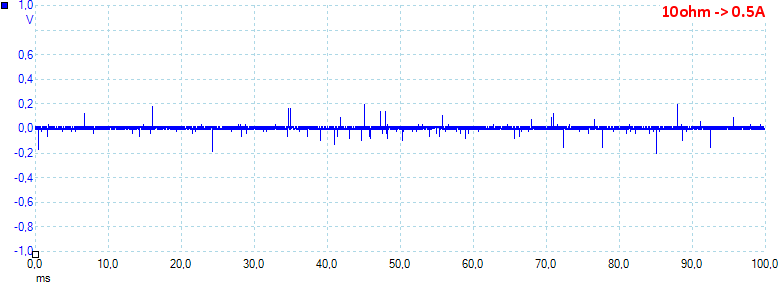
At 0.5A the noise is 14mV rms and 450mVpp.
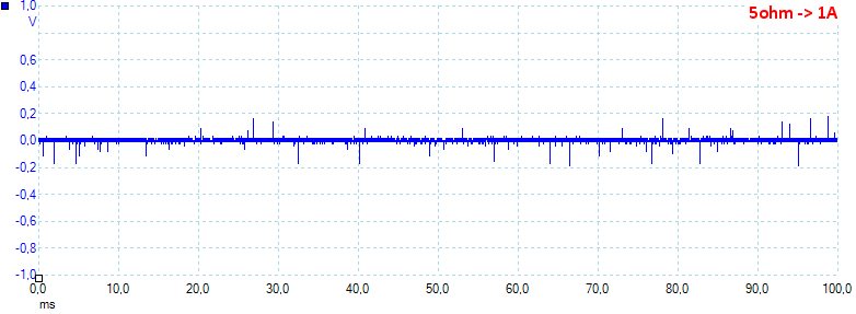
At 1A the noise is 17mV rms and 472mVpp.
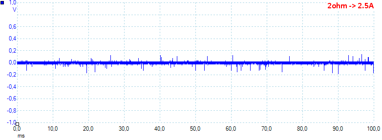
At 2.5A the noise is 21mV rms and 481mVpp.
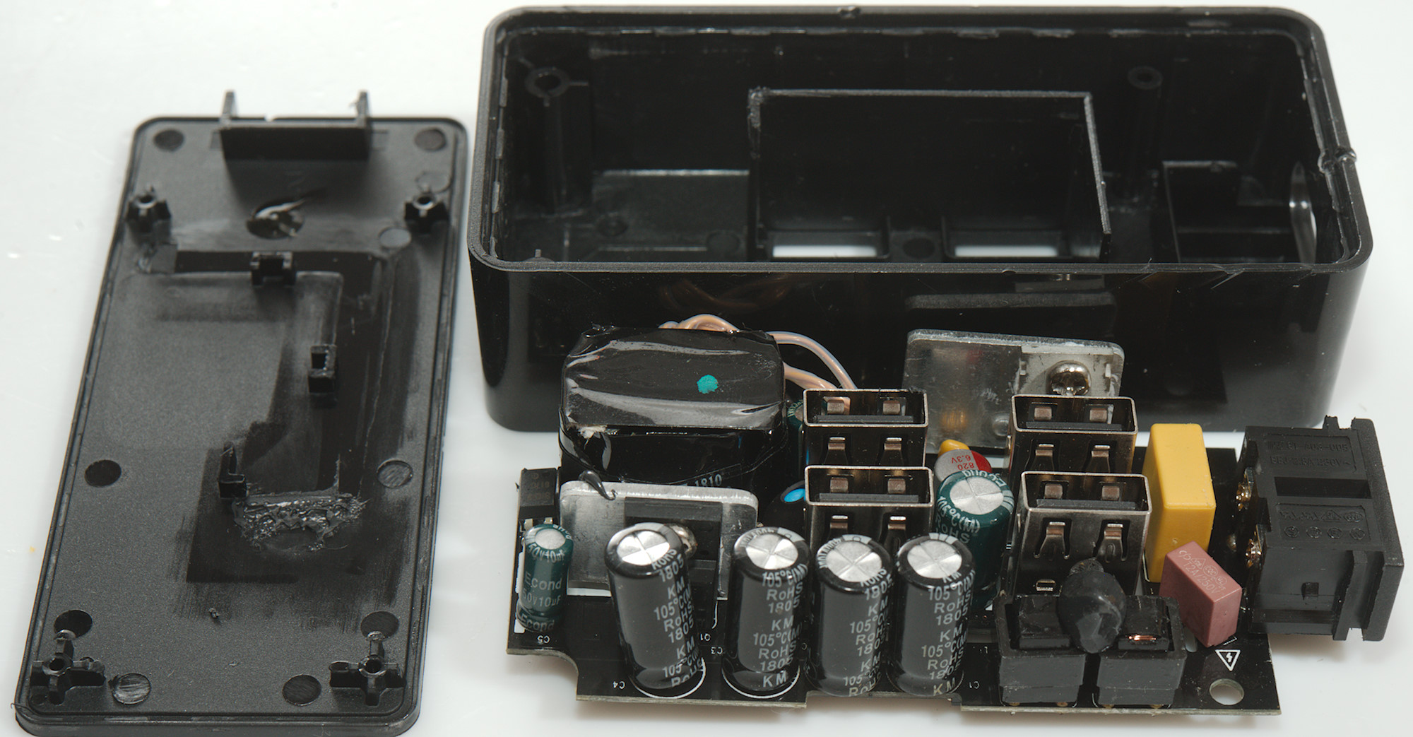
Tear down
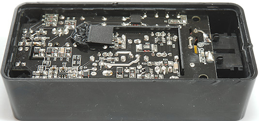
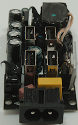
The bottom was glued on, it was a bit difficult to pry it loose. Notice the plastic shielding that poke through the circuit board, this is a very good sign for safety.
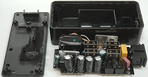
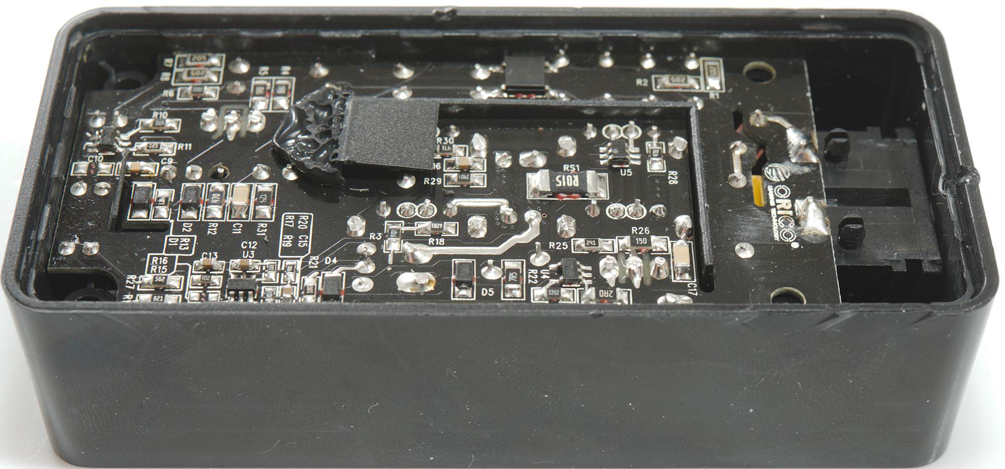
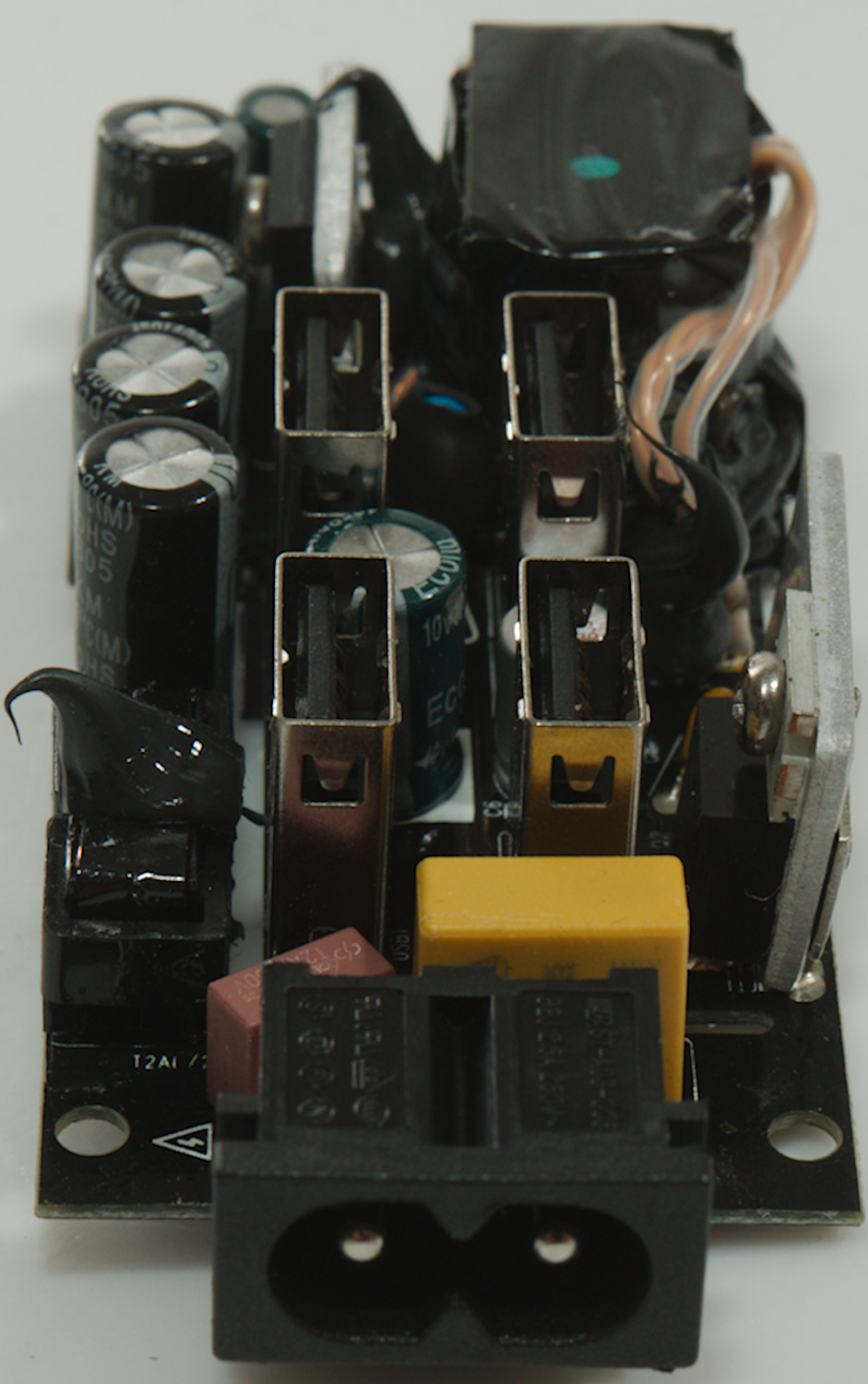
Circuit board is out, I could pull it out.
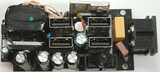
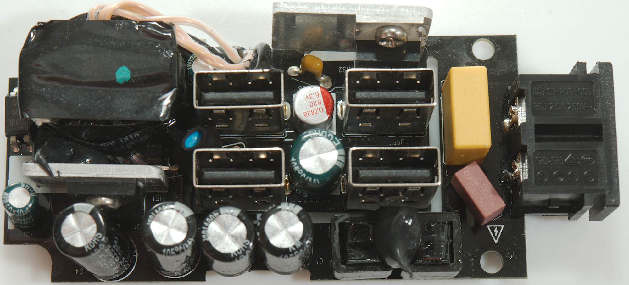
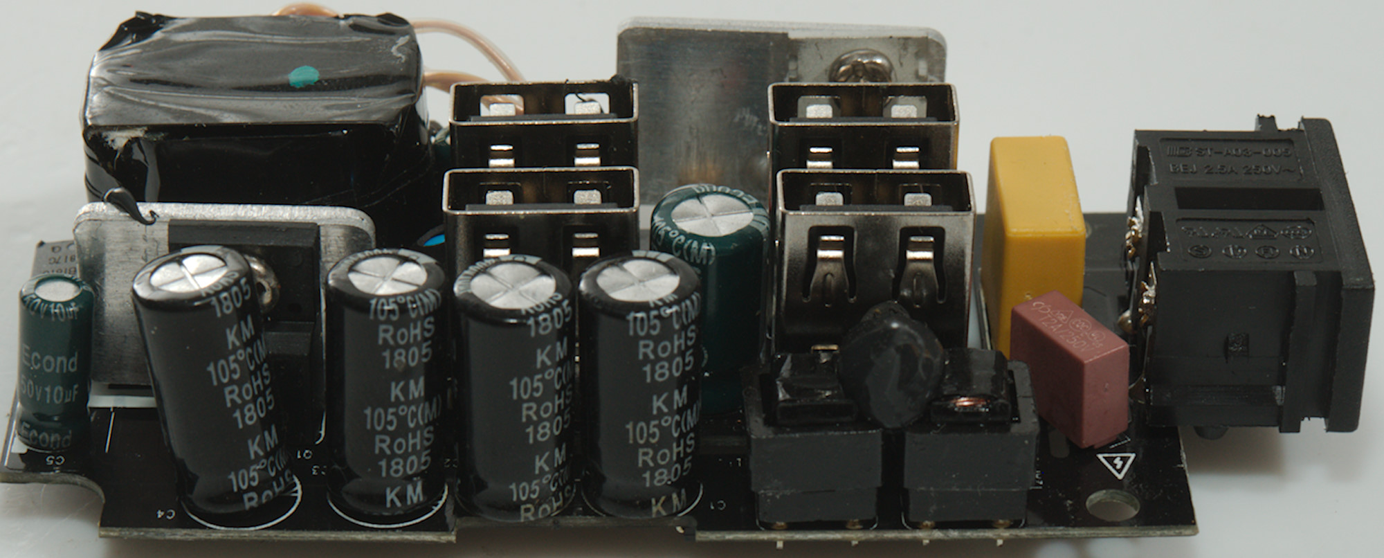
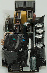
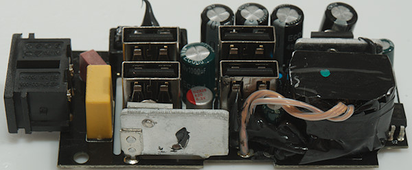
At the input is a fuse followed by two common mode coils and four smoothing capacitors. The main switcher transistor (Q1) is mounted on a small heatsink (HS1). Besides the main transformer is opto feedback (U2) and on the other side a safety capacitor (CY1). The rectifier (Q2) is mounted on a slightly larger heatsink (H2).

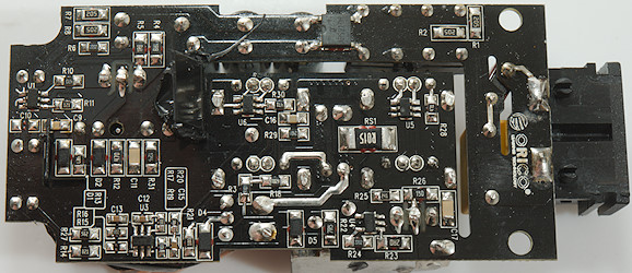
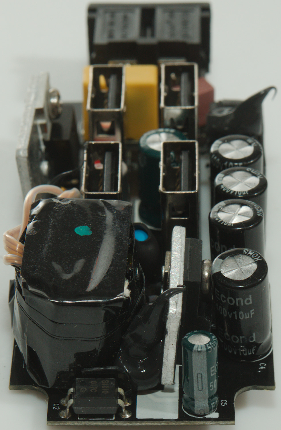
On this side is the input bridge rectifier, the mains switcher controller (U1: Marked 01H16).
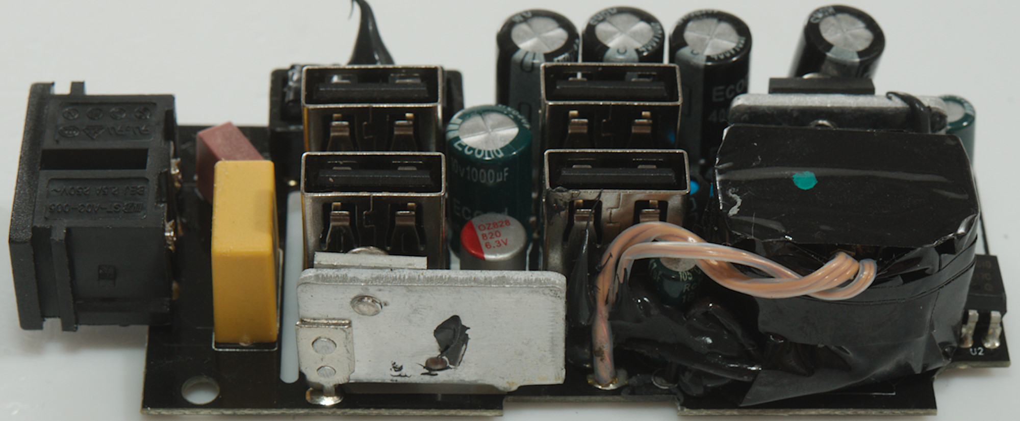
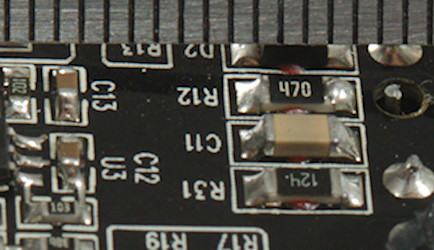
On the low volt side is a synchronous rectifier controller (U4: Marked I9HJB), a voltage and current control chip (U3: Marked G7L) with a current shunt (RS1: 15mOhm) and two dual auto coding chips (U5 & U6: D1524).
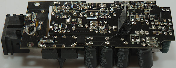
The distance between mains and low volt side is 6mm.
Testing with 2830 volt and 4242 volt between mains and low volt side, did not show any safety problems.
Conclusion
This is a very compact 4 output USB charger with automatic coding of the outputs, but it only has enough current to fast charge two devices at a time.
This is a fairly good charger for keeping a couple of USB devices charged.
Notes
Index of all tested USB power supplies/chargers
Read more about how I test USB power supplies/charger
How does a usb charger work?