Power Falcon 45W PS300E-ACT-10 UK
Official specifications:
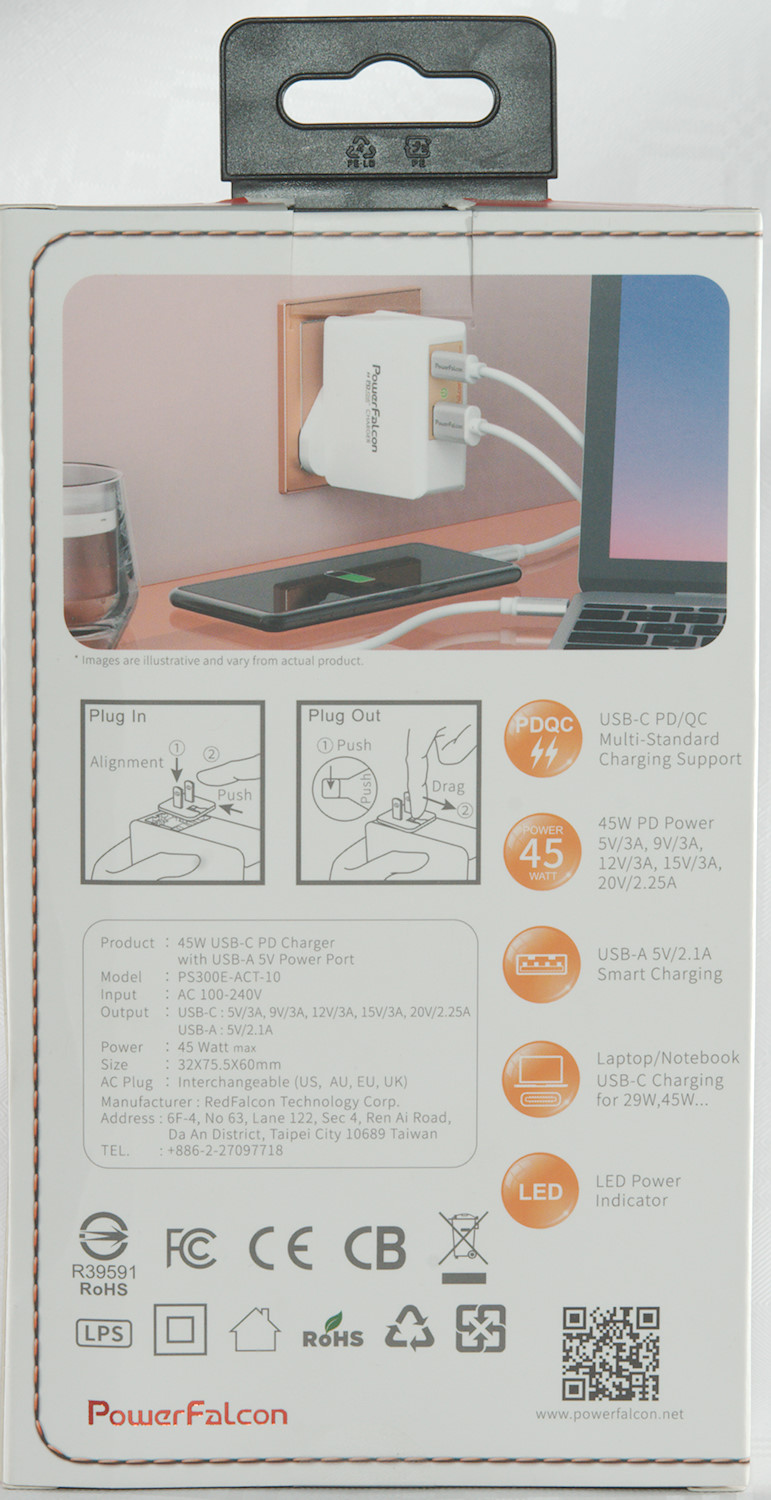
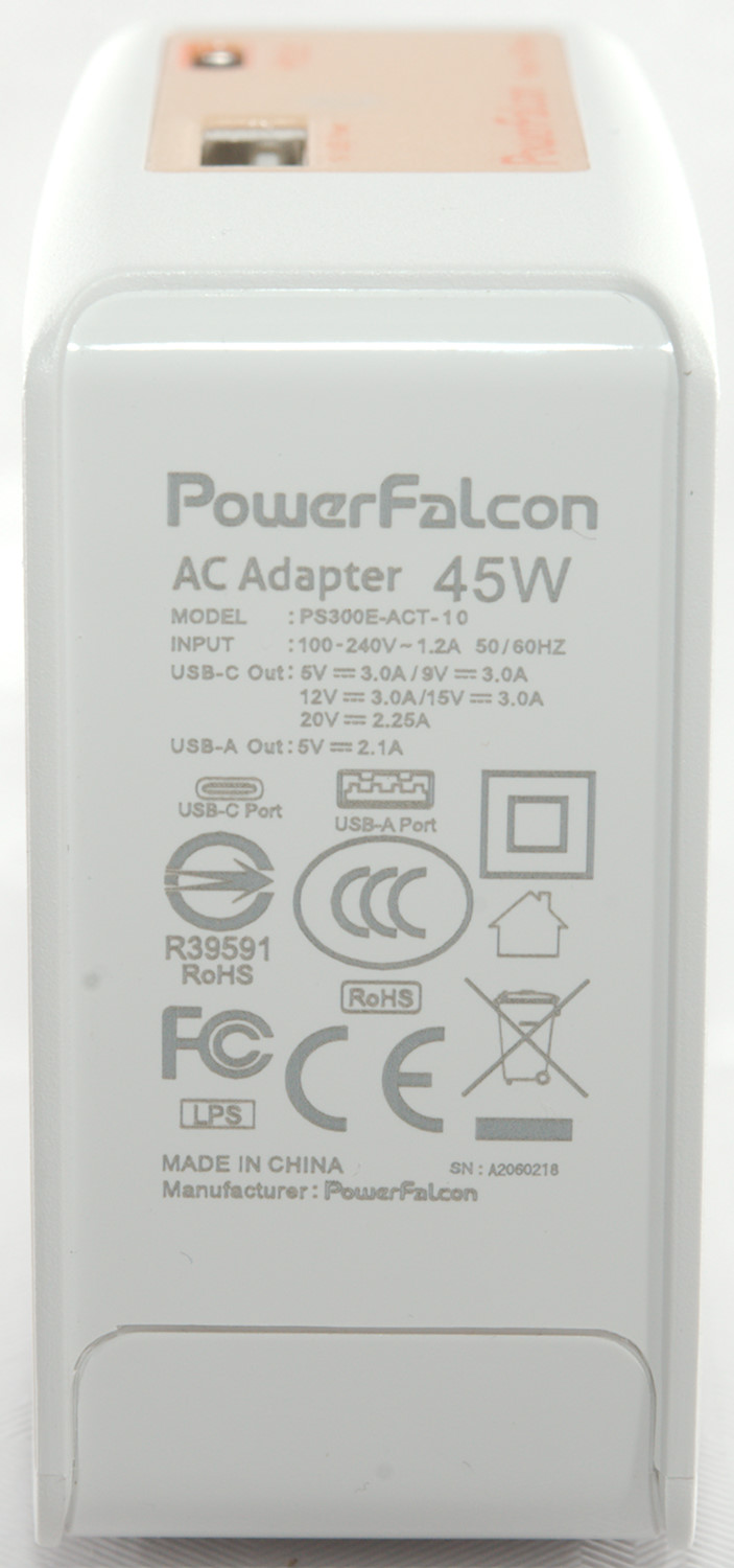
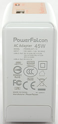
- Model: PS300E-ACT-10
- Input: 100-240VAC
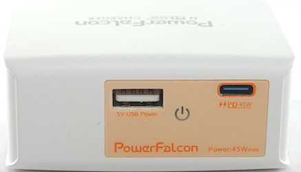
- Output: USB-A 5V/2.1A
- Output: USB-C: 5V/3A, 9V/3A, 12V/3A, 15V/3A, 20V/2.25A
- Power: 45 Watt max.
- Size: 32 x 75.5 x 60mm
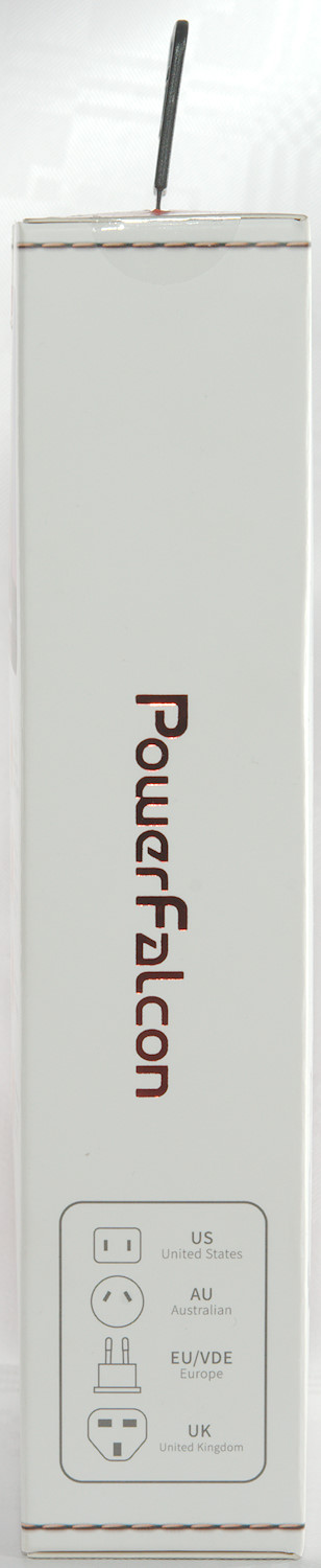
- AC Plug Interchangeable (US, AU, EU, UK)
I got it from a reader
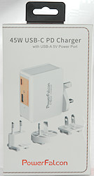
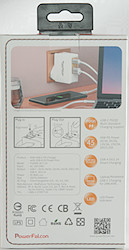

The charger arrived in a box with specifications and photos of the charger.
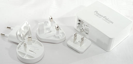
The box contained the charger and four different mains plugs, but no instruction sheet.
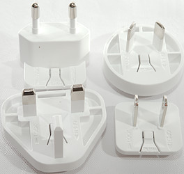
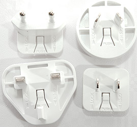
All the different plugs.
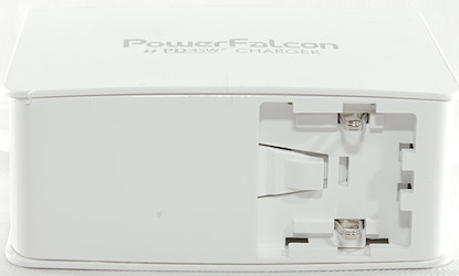
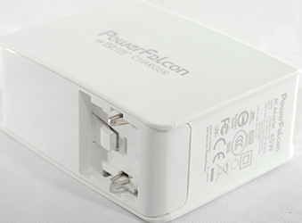
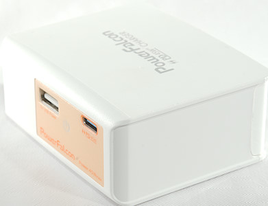
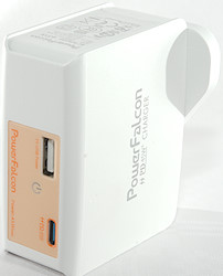
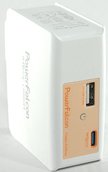
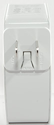
Charger without any plug.
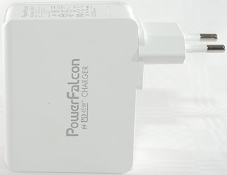
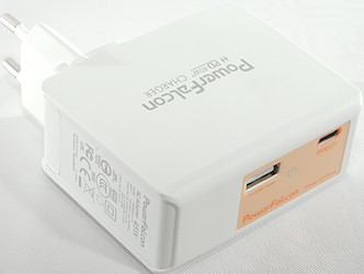
EU plug.

AU plug
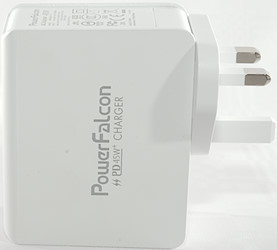
UK plug
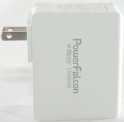
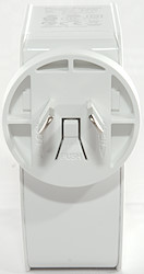
US plug
Measurements
- Normal USB is auto code with Apple 2.4A and DCP.
- USB-C PD have 5V 3A, 9V 3A, 12V 3A, 15V 3A, 20V 2.25A.
- USB-C also has a DCP, Apple 2.4A and QC3 coding, it is also supposed to support FCP & QC4, but I did not detect it.
- Power consumption when idle is 0.07 watt.
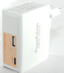
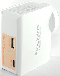
- Behind the power switch symbol is a green led (It is not a switch).
- Default USB-C output is off.
- Weight: 129.1g without plug, the plug is US:6.2g, AU:11.5g, EU:15.9g, UK:16.0g
- Size: 75.3 x 60.0 x 32.0 mm without plug.
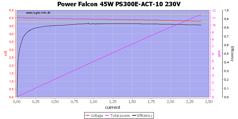
The USB-A output can deliver about 2.3A, this is fine for a 2.1A rated output
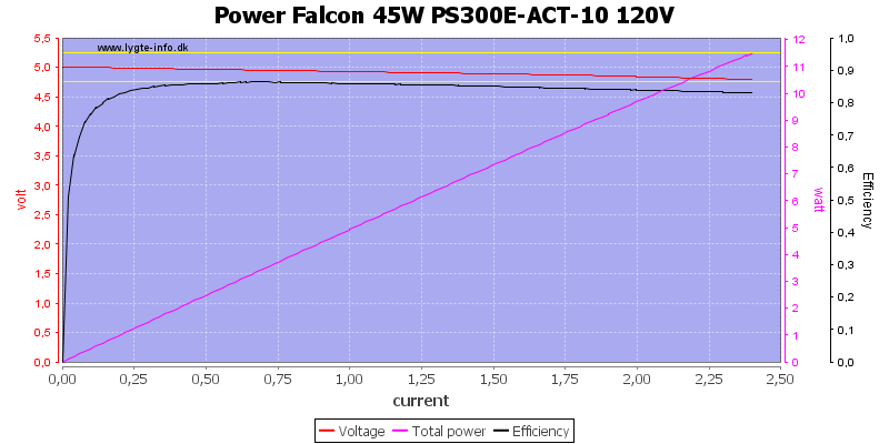
The current is the same at 120VAC
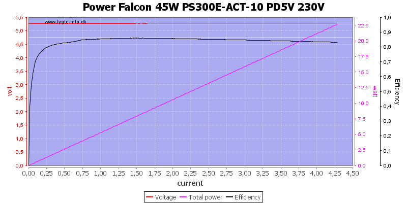
PD can deliver about 4.2A at 5V, this is a bit much for a 3A rated output.
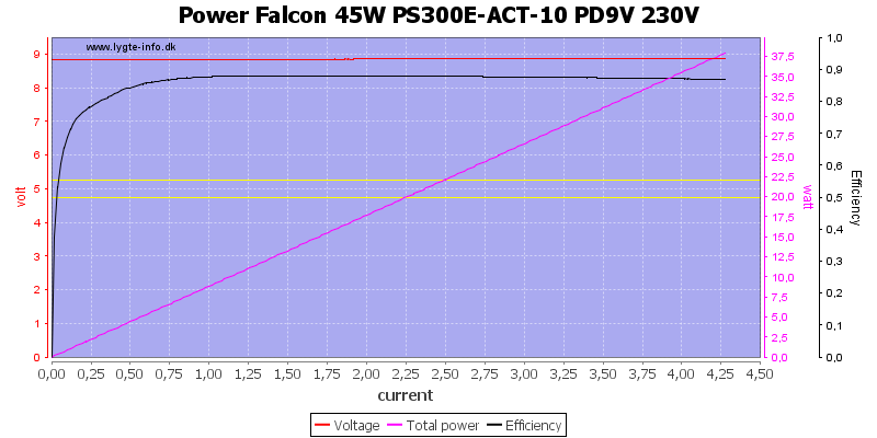
Output is the same at 9V
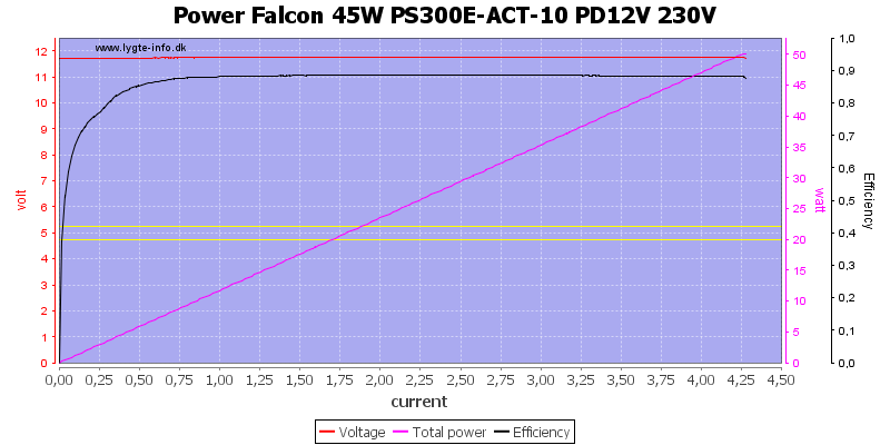
At 12V
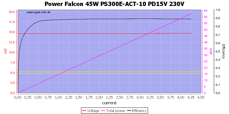
And at 15V
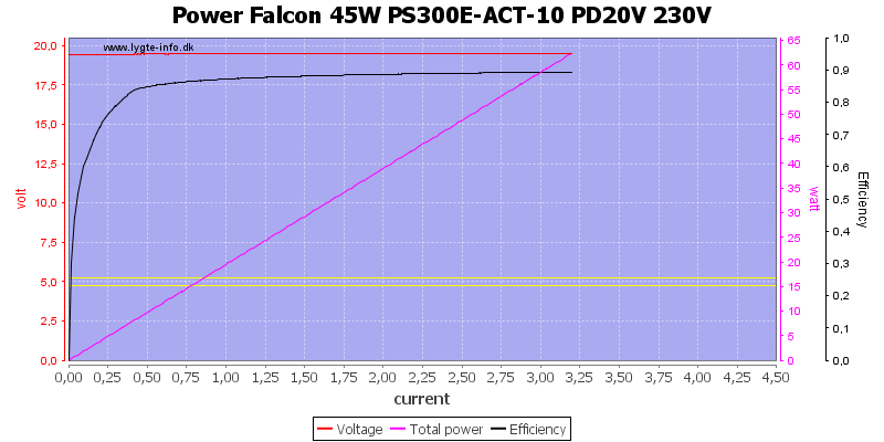
At 20V the output is "only" 3.2A again well above the rated 2.25A
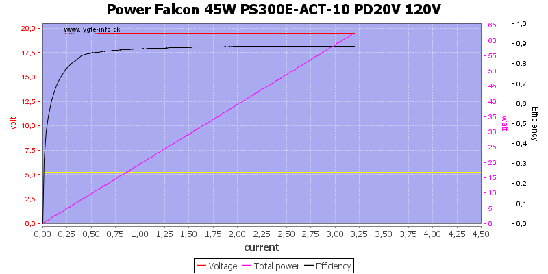
And the same at 120VAC
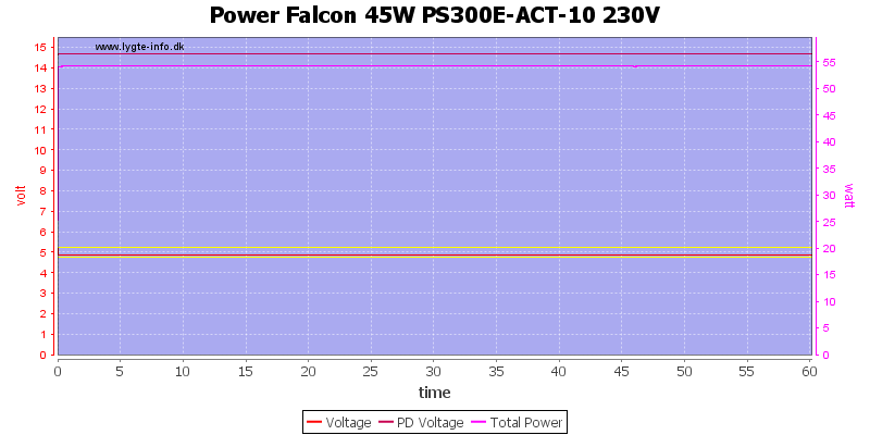
Here I did a one hour run at 5V 2.1A and 15V 3A, this worked fine.
The temperature photos below are taken between 30 minutes and 60 minutes into the one hour test.
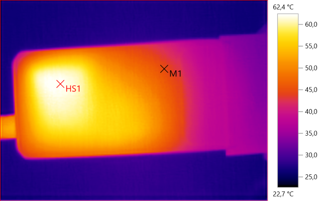
M1: 44.9°C, HS1: 62.4°C
HS1 is from the heatsink.
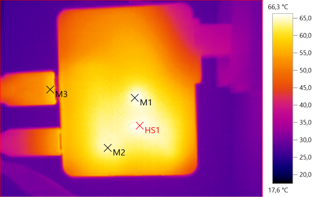
M1: 65.8°C, M2: 64.3°C, M3: 56.9°C, HS1: 66.3°C
HS1 is the transformer, M1 is the snubber network and M2 is the rectifier transistor.
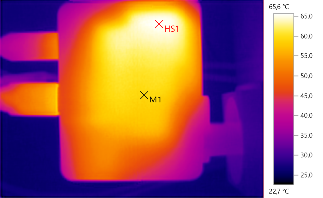
M1: 59.6°C, HS1: 65.6°C
Both M1 and HS1 is the transformer, the large area is due to the heatsink.
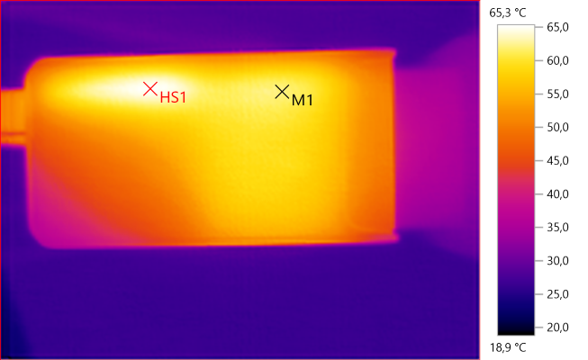
M1: 62.1°C, HS1: 65.3°C
HS1 is the circuit board due to the rectifier transistor, M1 and below is the heatsink
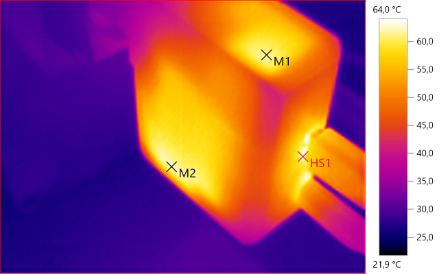
M1: 61.2°C, M2: 62.1°C, HS1: 64.0°C
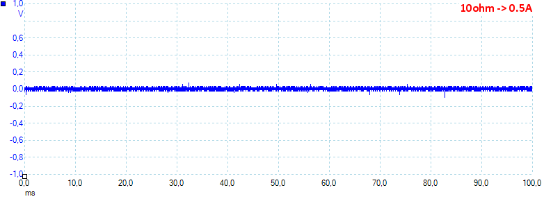
At 5V 0.5A the noise is 17mV rms and 282mVpp.
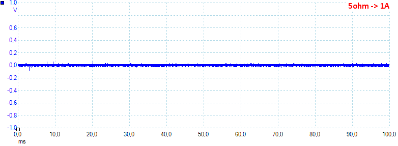
At 5V 1A the noise is 14mV rms and 209mVpp.
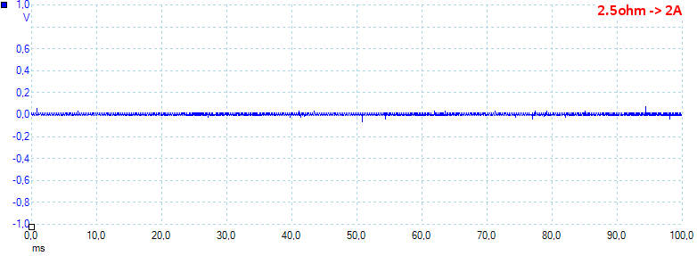
At 5V 2A the noise is 8mV rms and 214mVpp.
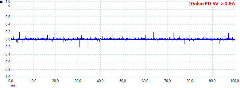
At 5V 0.5A the noise is 25mV rms and 640mVpp.
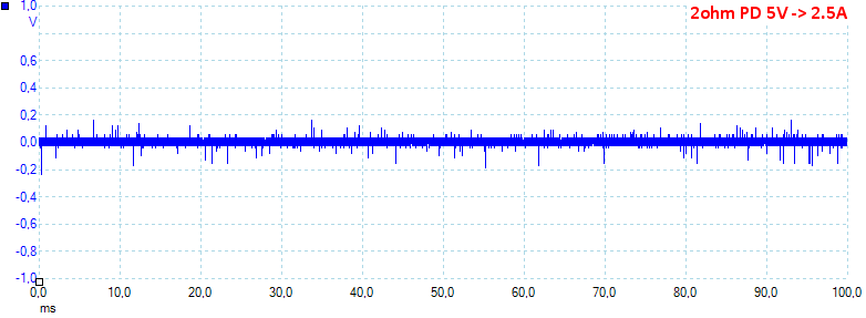
At 5V 2.5A the noise is 31mV rms and 516mVpp.
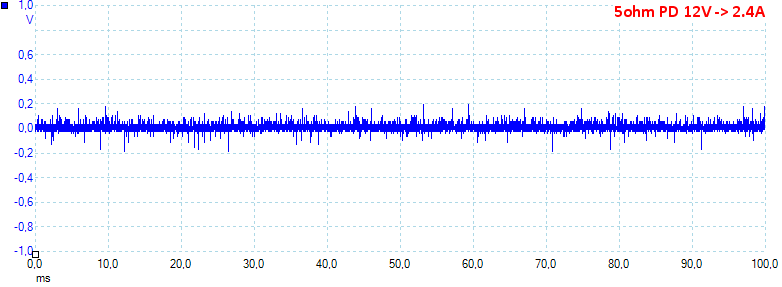
At 12V 2.4A the noise is 17mV rms and 613mVpp.
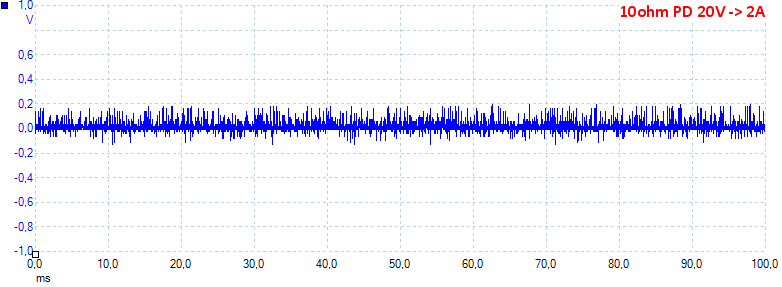
At 20V 2A the noise is 43mV rms and 428mVpp.
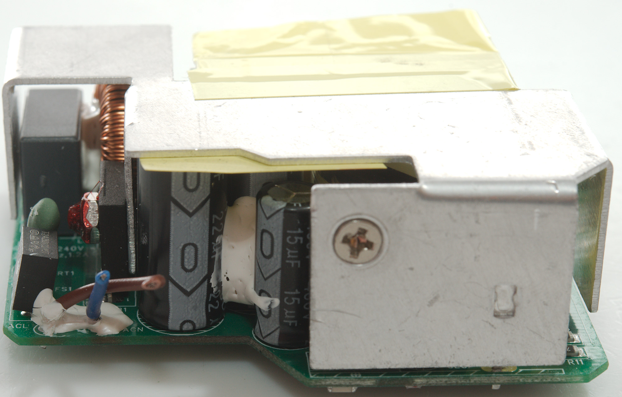
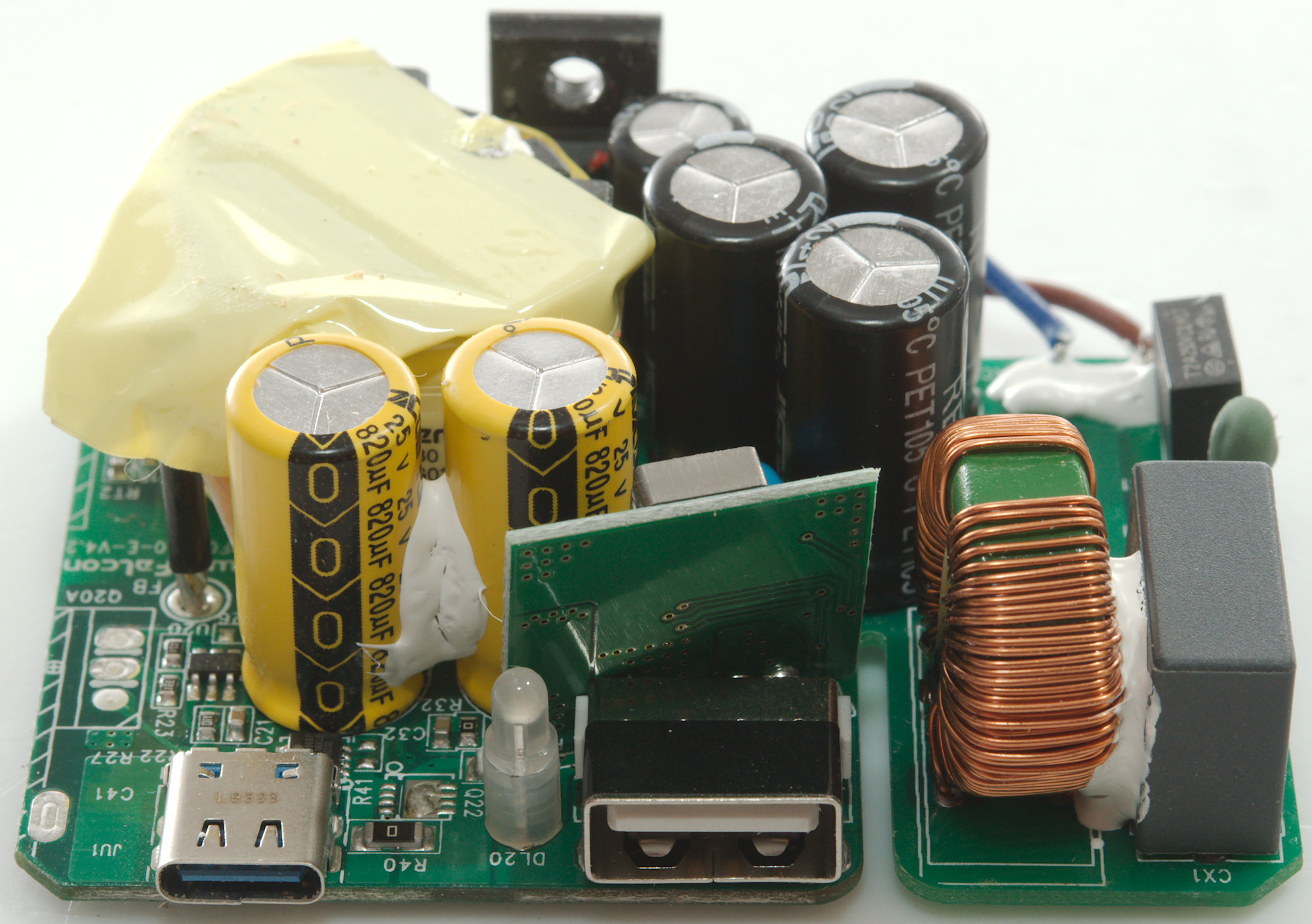
Tear down
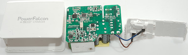
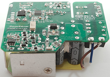
I cracked most of the glue by whacking at the end of the bottom with a mallet and metal rod to direct the force, then used a screwdriver to break the bottom off.
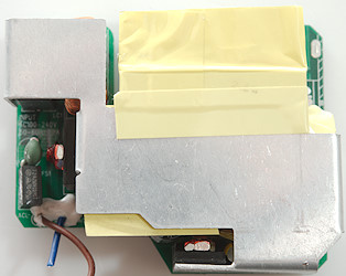
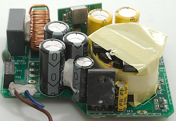
Most of the top is a large heatsink, but a fuse (FS1), a inrush current limiter (RT) and a bridge rectifier (DB1) is visible in the corner where the mains leads are connected.
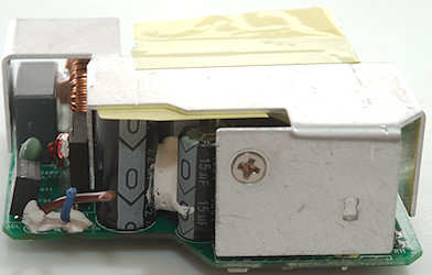
To see below the heatsink I removed one screw, the other was not accessible and I desoldered the bridge rectifier instead.
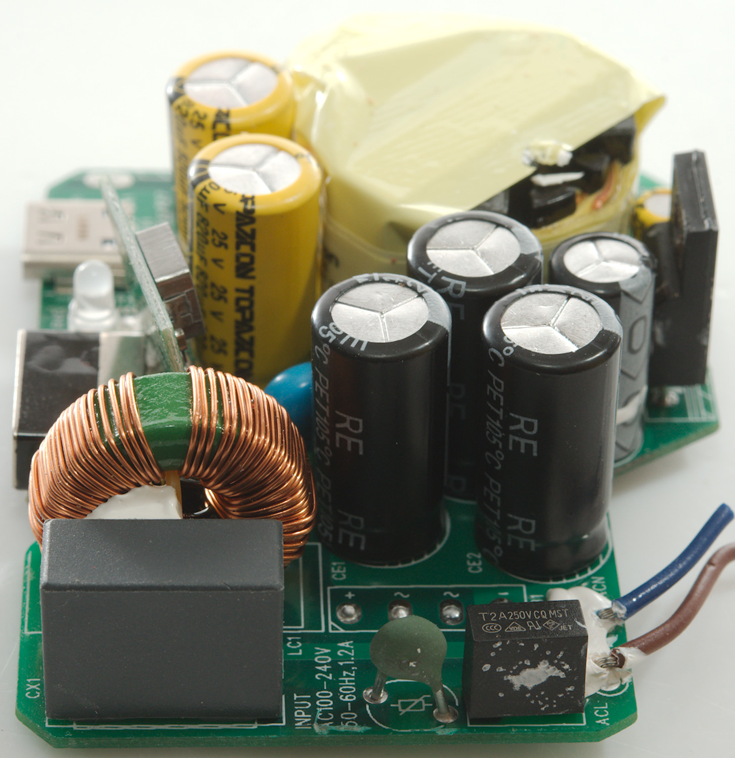
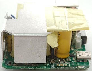
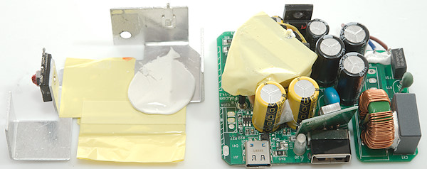
Near the missing bridge rectifier is the common mode coil (LC1). There is a safety capacitor (CY). The mains switcher transistor (Q2) is at the top and was screwed to the heatsink.
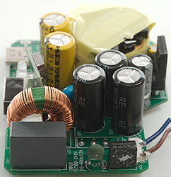
On the low volt side is a 6 pin chip (U20: Marked IAZEJ), it must be a synchronous rectifier controller and just behind the USB-C connector is a power mos (Q21: SPP8637 P-channel), probably for on/off control.
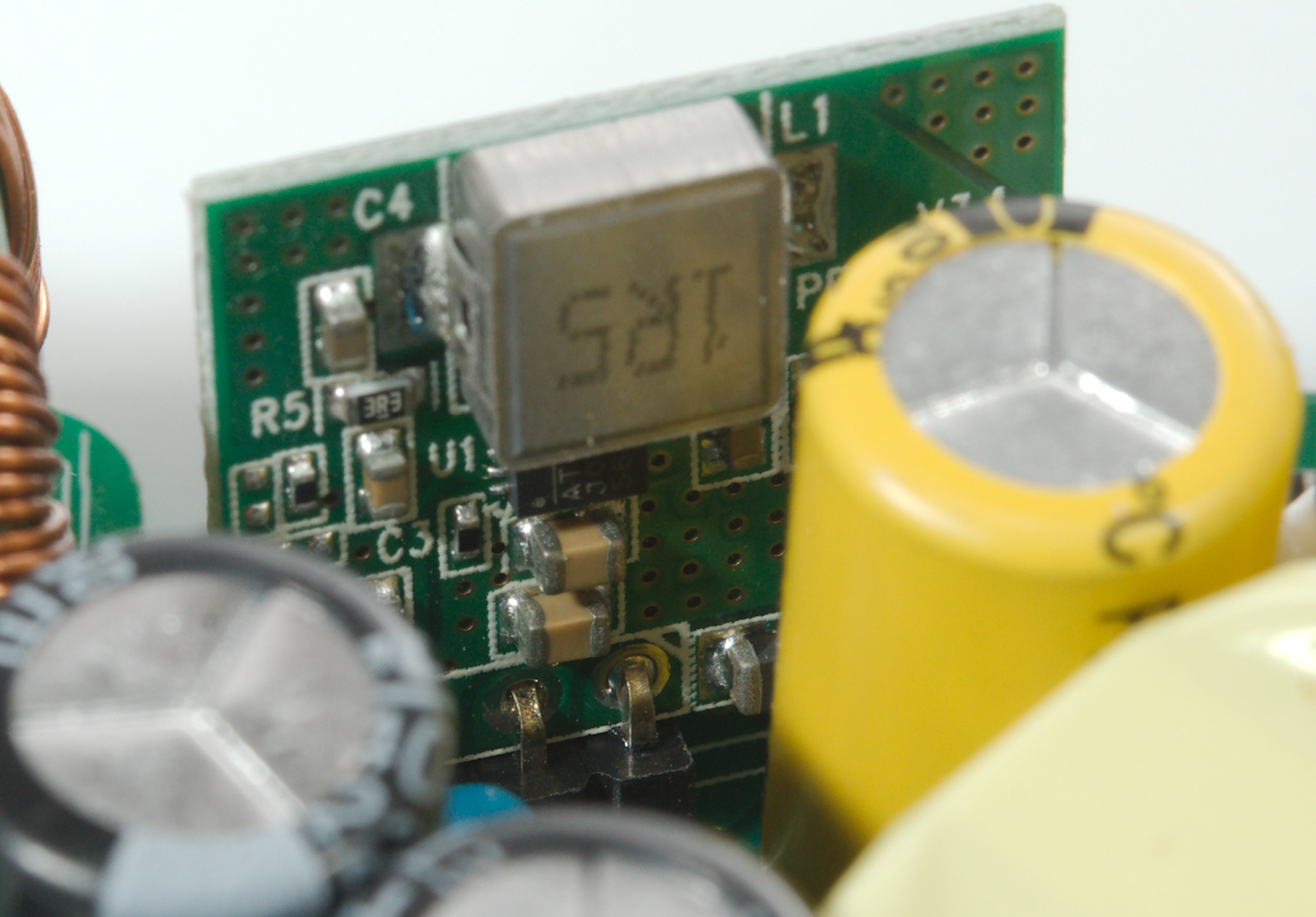
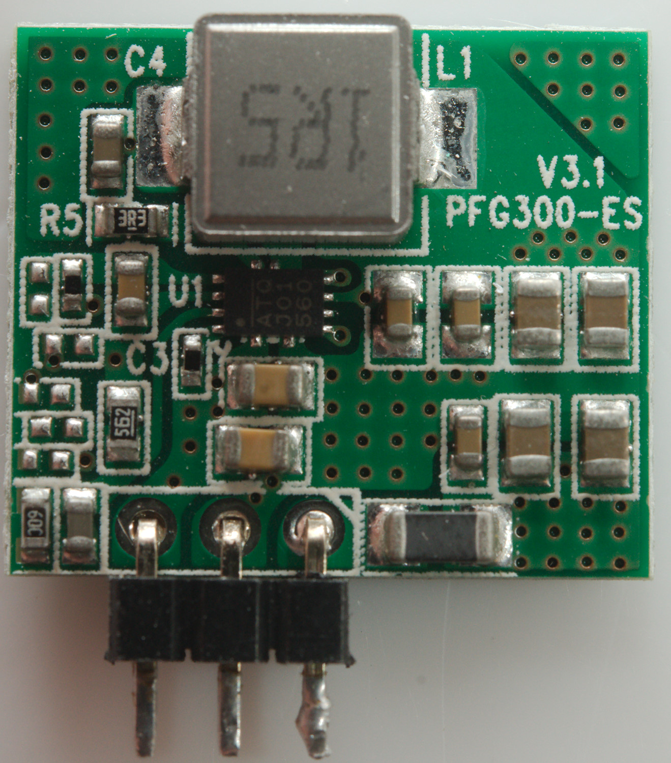
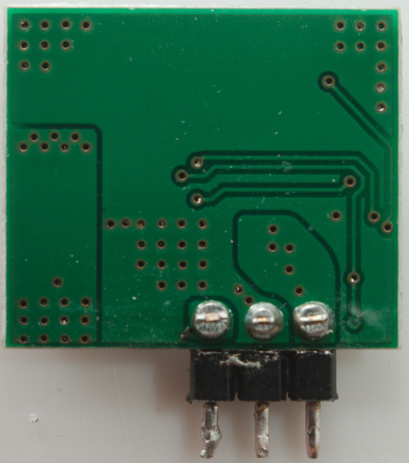
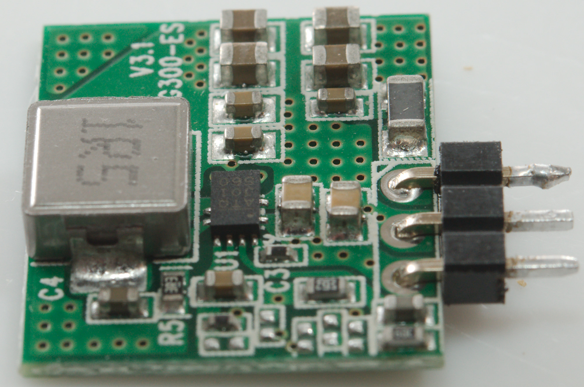
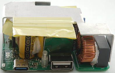
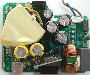
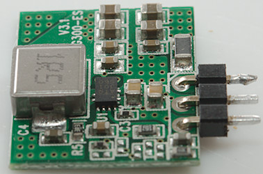
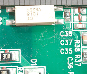
The standard USB output do not have a separate transformer, instead it has a buck converter on a small module.


The buck converter module in place.
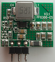

The buck converter module with an inductor (L1) and a switcher (U1: Marked ATQ / J01 / 560)
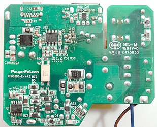
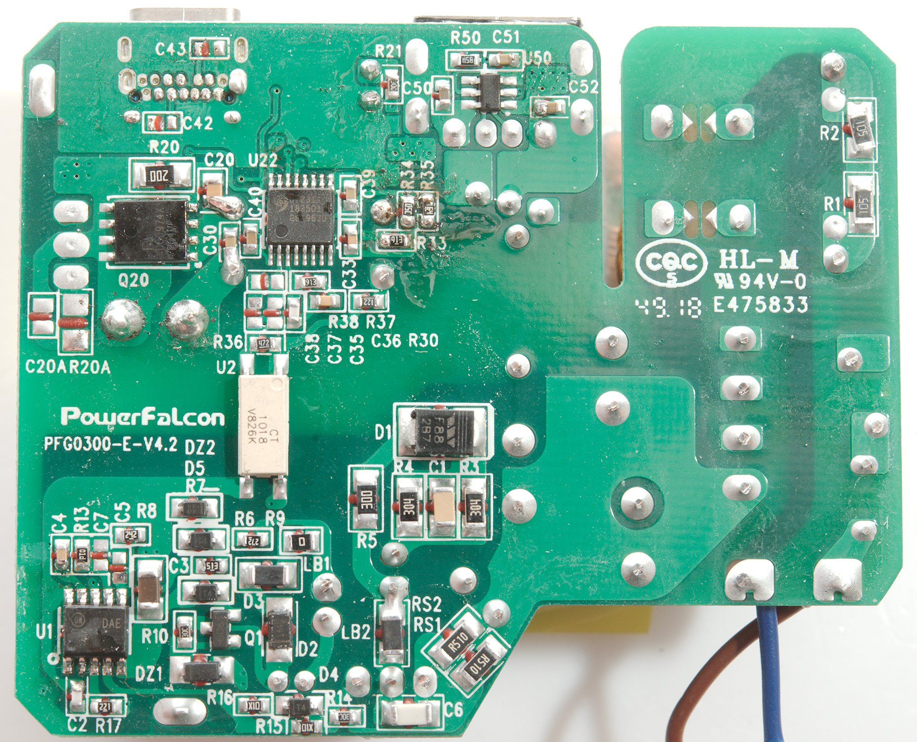
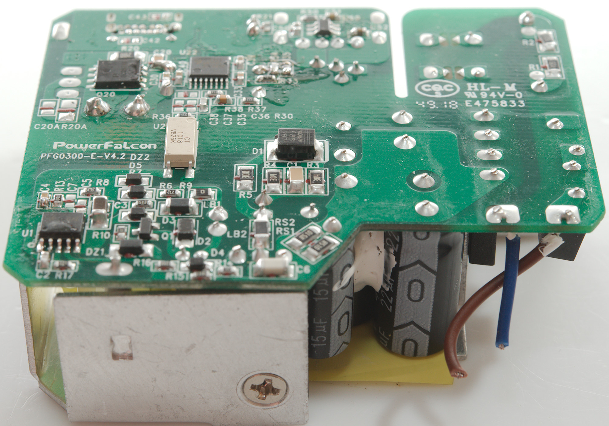
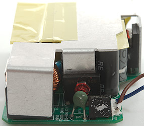
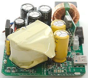
On this side is the mains switcher controller (U1) and a very long opto coupler (DZ2) for feedback. On the low volt side is a USB PD controller (U22: CY2311), the synchronous rectifier transistor (Q20) and a charge optimizer IC for standard USB output.
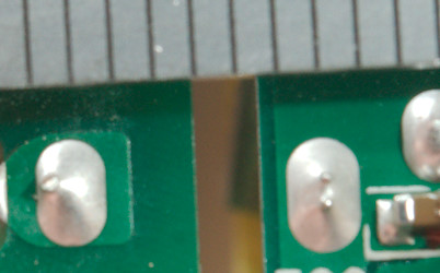
The long opto coupler gives a good isolation distance, but over the slot the distance is slightly low, it is supposed to be 4mm and looks more like 3.5mm, this could have been a problem, but the box has a plastic shield that goes into the slot and secures perfect isolation.
The charger passed the 2830 volt and 4242 volt test, this means it is it is fairly safe.
Conclusion
This is an interesting design with only one mains transformer, but it works well. The noise is low, the coding is fine and there is a decent amount of power on both connectors. It can charge a laptop and a phone at the same time.
I will call it a good charger.
Notes
The charger was supplied by a Mostly Melbourne for review.
Index of all tested USB power supplies/chargers
Read more about how I test USB power supplies/charger
How does a usb charger work?