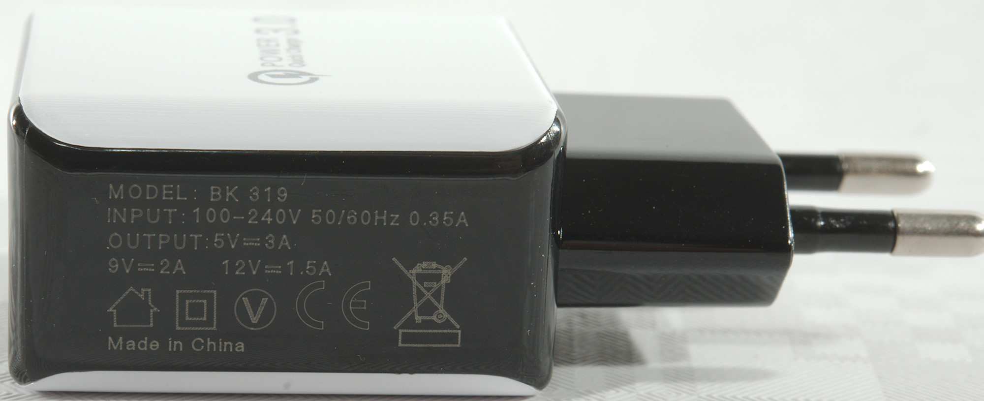
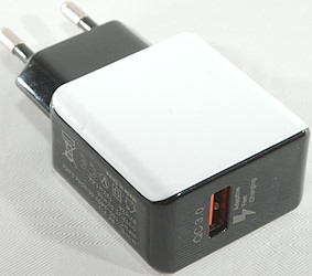
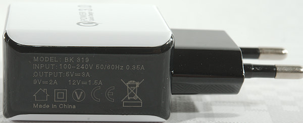
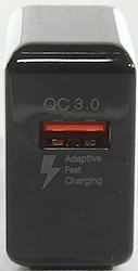
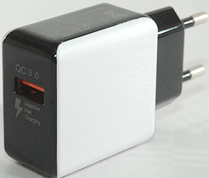
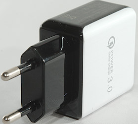
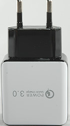
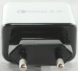
QC3 charger 19.2W BK 319
Official specifications:
- Quick Charge 3.0
- 19.2 Watt
- US or EU plug
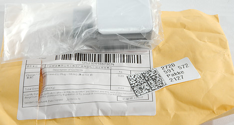
I got it from Wish.com
Measurements
- Power consumption when idle is 0.15 to 0.3 watt
- Minimum QC3 voltage is 4.3V, but selecting it is not very reliable.
- USB output is coded as Apple 2.4A, DCP, QC2, Samsung-AFC, Huawei-FCP
- Weight: 40.4g
- Size: 79.5 x 42.4 x 23.9mm
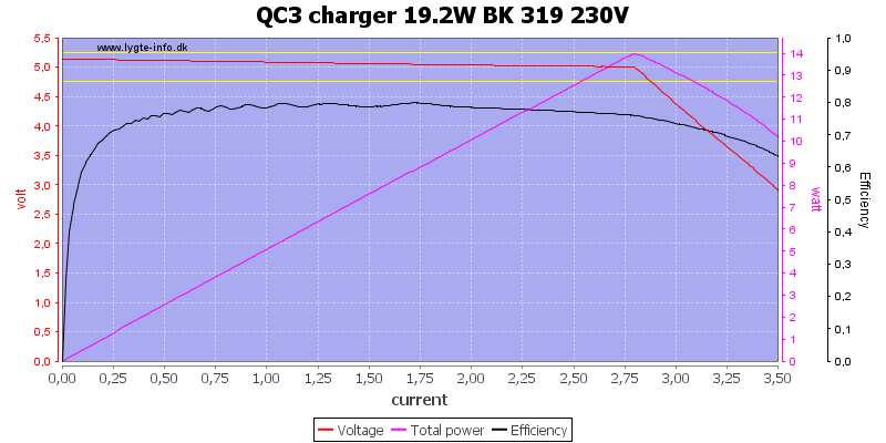
The output current is not the rated 3A, but about 2.8A, then the voltage starts to drop. It do not look like the charger has over current protections, instead it limits the power (My equipment terminates the test when output voltage is 3V).
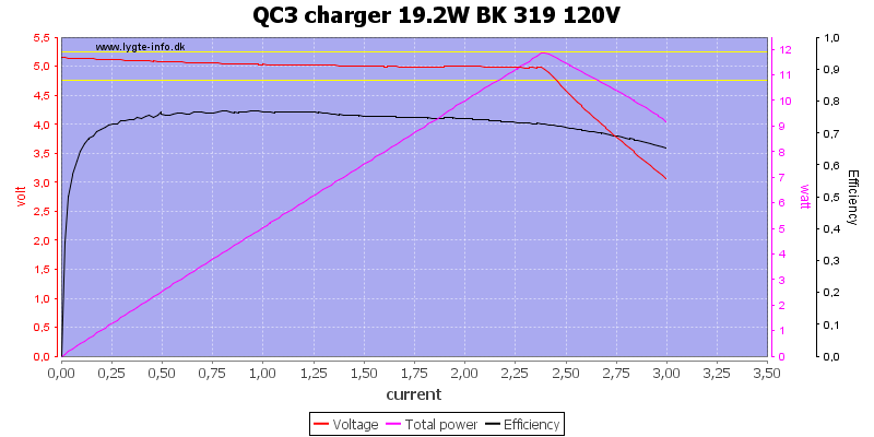
At 120VAC the output current is only about 2.4A.
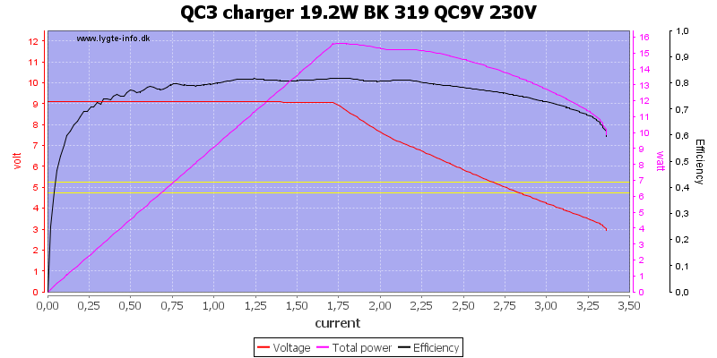
At 9V the output current is about 1.7A, again below the rated 2A and there is no over current cutout.
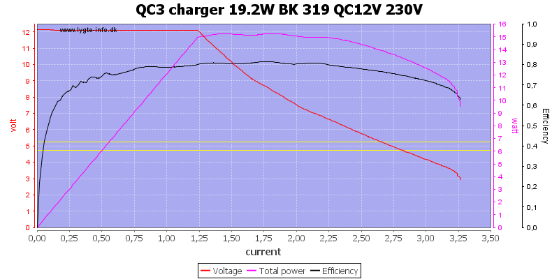
And at 12V the current is 1.2A, not the rated 1.5A.
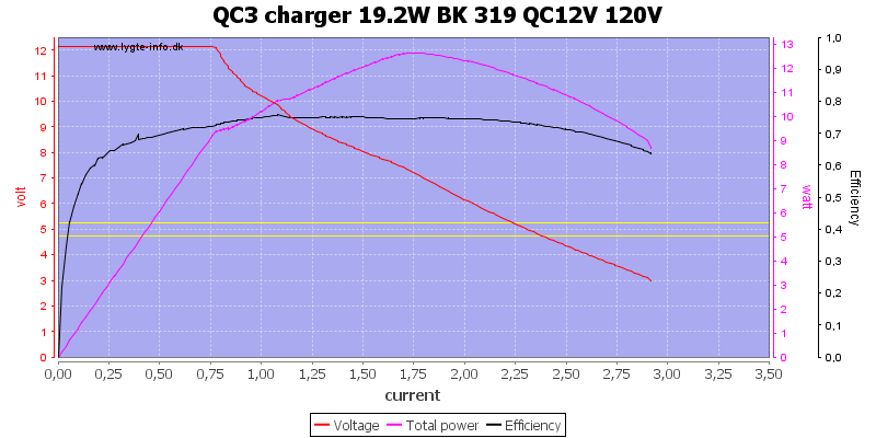
Reducing input voltage to 120VAC reduces the output current to 0.7A, this is way below rating.
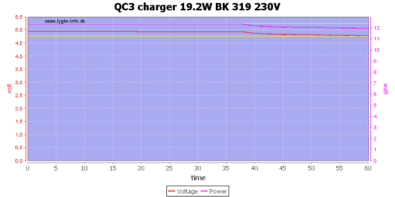
I did the 1 hour test at 5V 2.5A, the output voltage dropped a bit when the charger got hot.
The temperature photos below are taken between 30 minutes and 60 minutes into the one hour test.
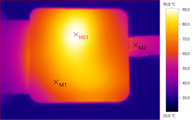
M1: 69.3°C, M2: 55.7°C, HS1: 90.8°C
HS1 is the switcher chip.
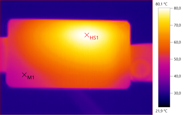
M1: 48.5°C, HS1: 80.1°C
HS1 is the rectifier diode.
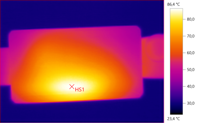
HS1: 86.4°C
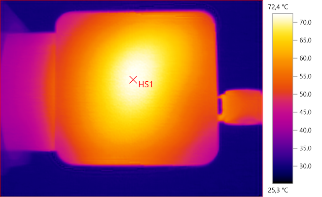
HS1: 72.4°C
HS1 is the transformer.
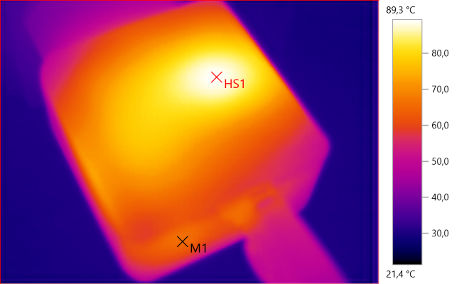
M1: 65.7°C, HS1: 89.3°C
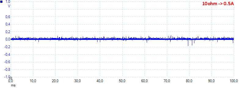
At 0.5A load the noise increases to 27mV rms and 618mVpp.
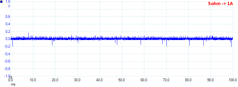
At 1A load the noise increases to 23mV rms and 904mVpp.
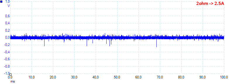
At 2.5A load the noise increases to 34mV rms and 869mVpp.
At 9V 0.9A load the noise increases to 51mV rms and 693mVpp.
At 12V 1.2A load the noise increases to 36mV rms and 662mVpp.
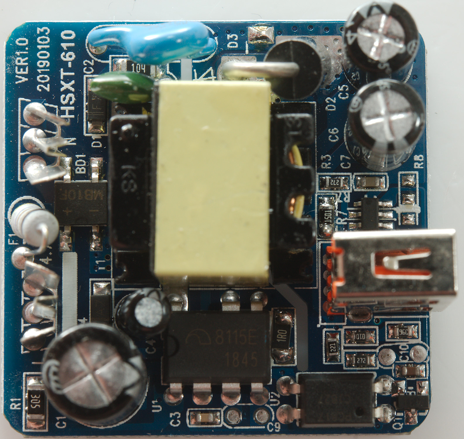
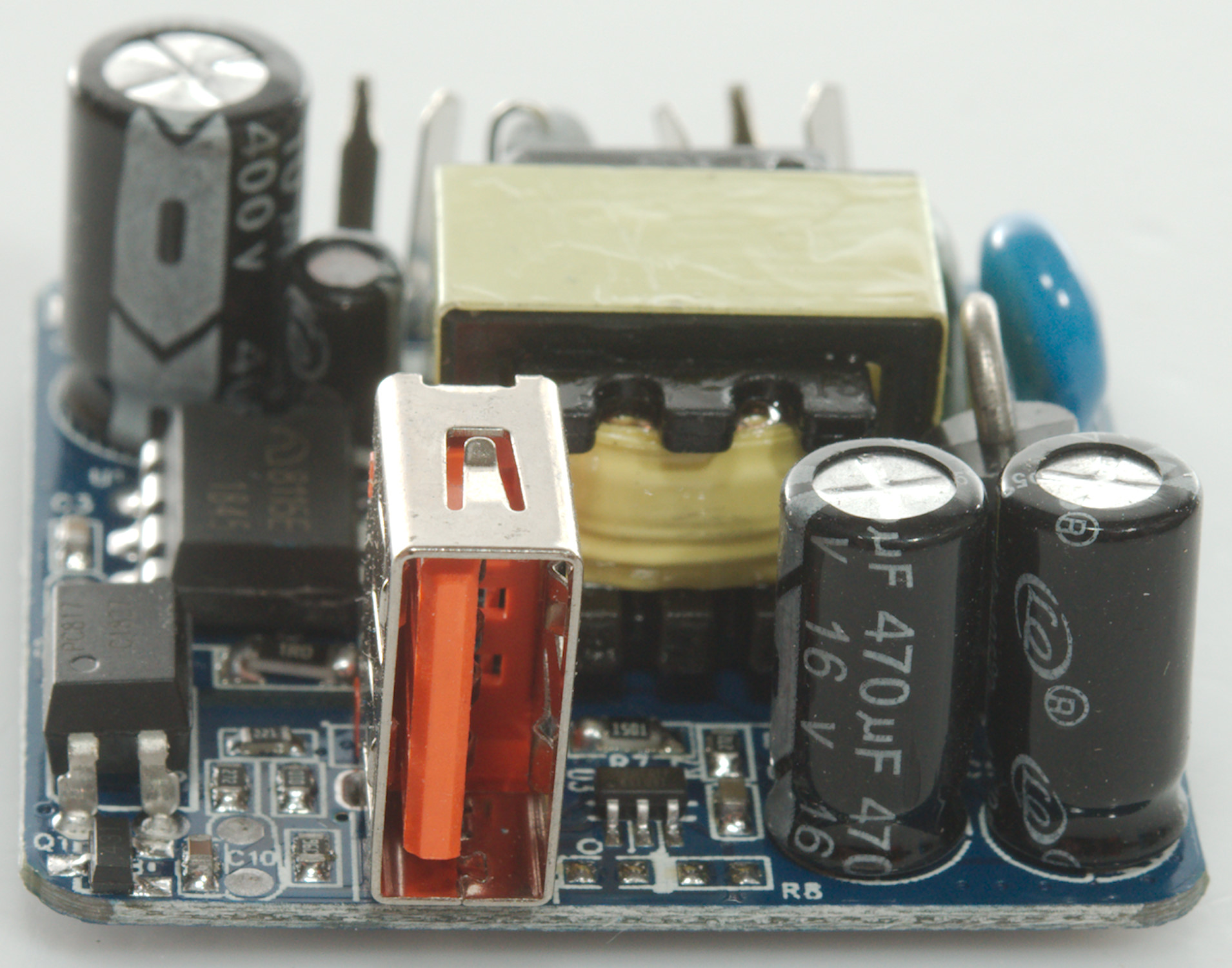
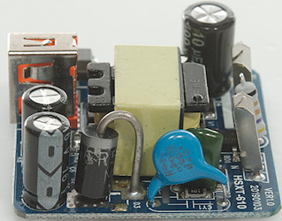
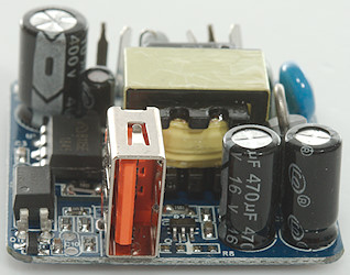
Tear down
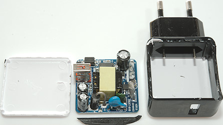
Some pressure with my vice and I could crack the glue and plastic to open it.
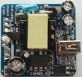
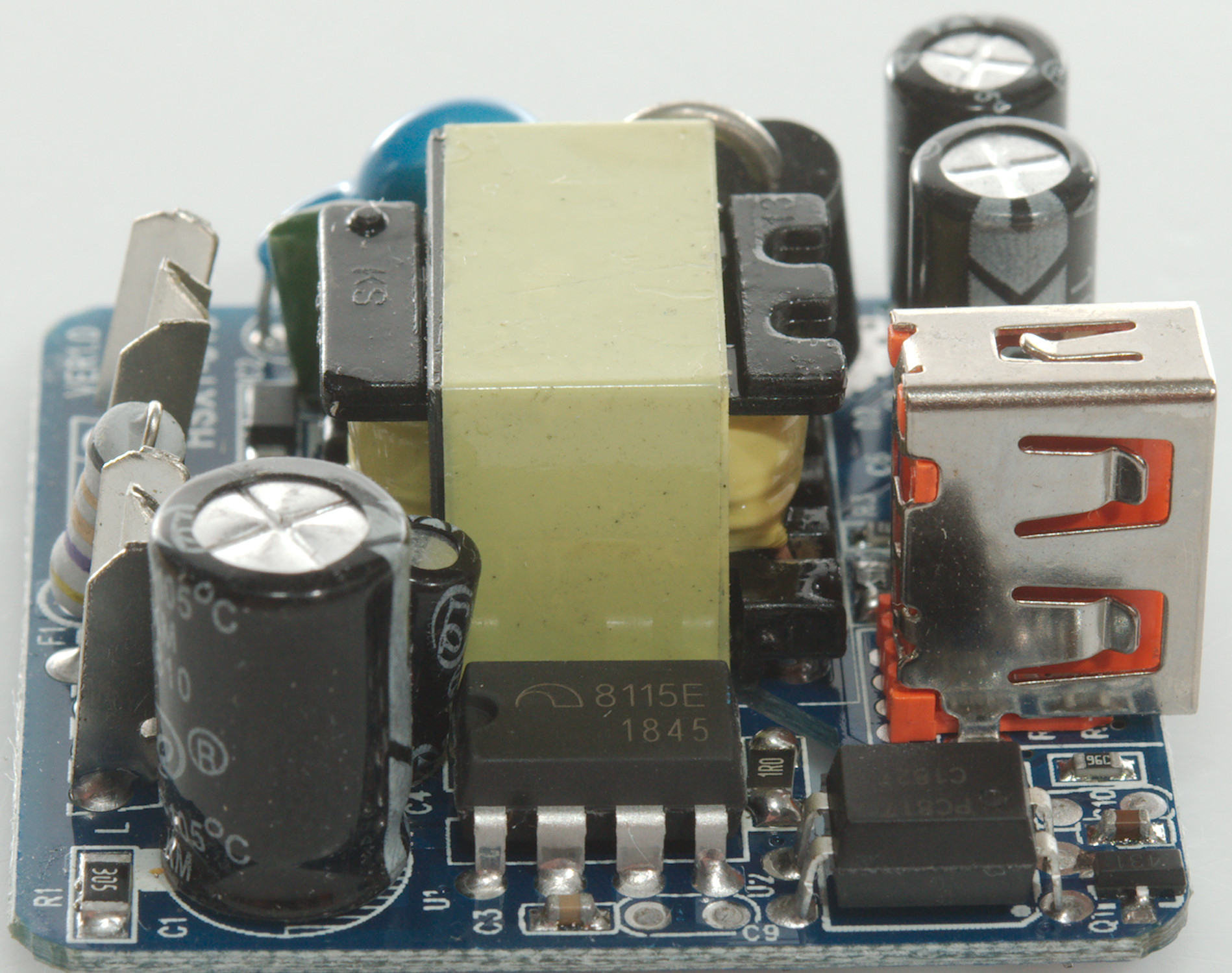
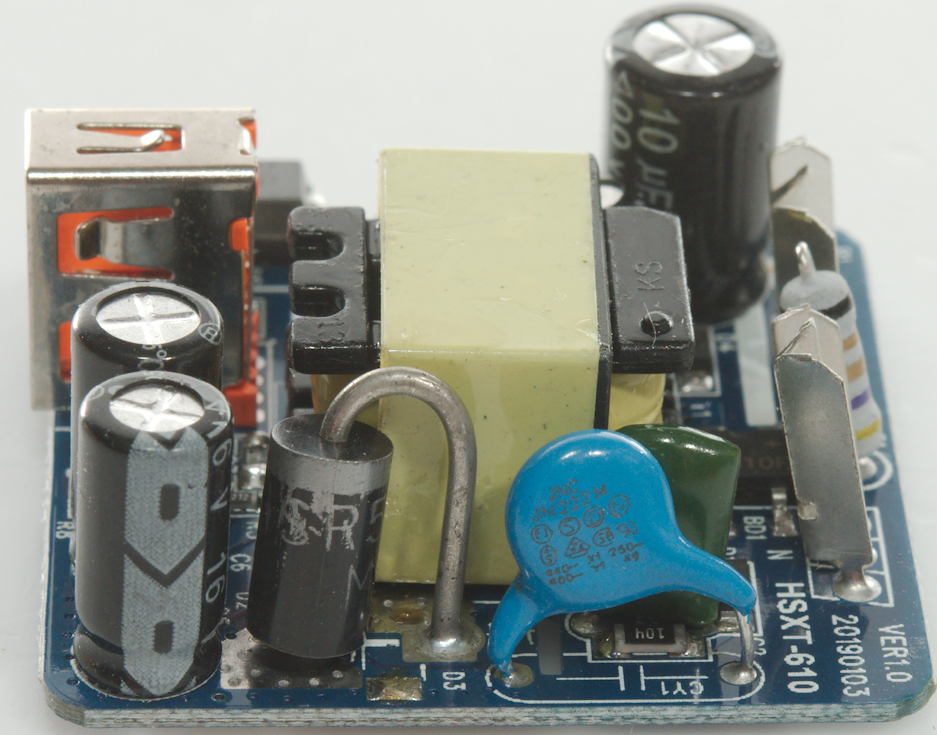
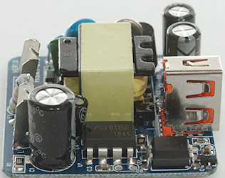
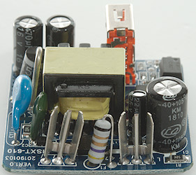
At the mains input is a fusible resistor as fuse (F1) and a bridge rectifier (BD1), the mains switcher (U1: marked 8115E / 1845) with opto feedback (U2). There is a safety capacitor between mains and low volt side and a large rectifier diode on the low volt side.
Beside the USB connector is a small QC3 controller chip (U3: Marked 6601Q1F / W91091).
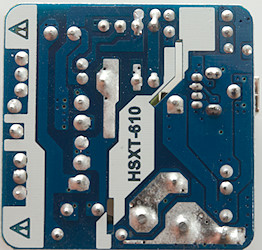
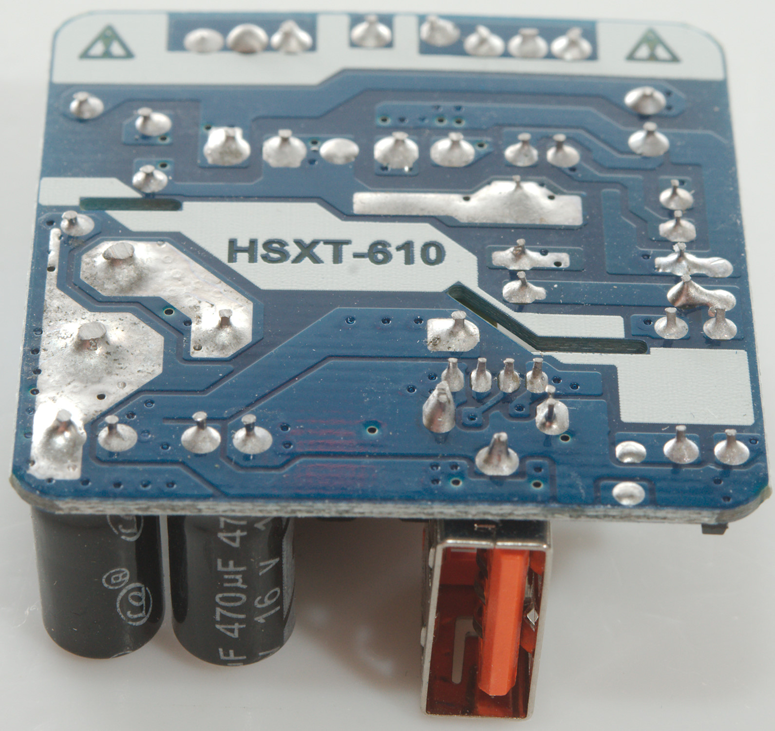
There is nothing on this side.
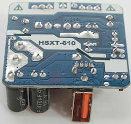
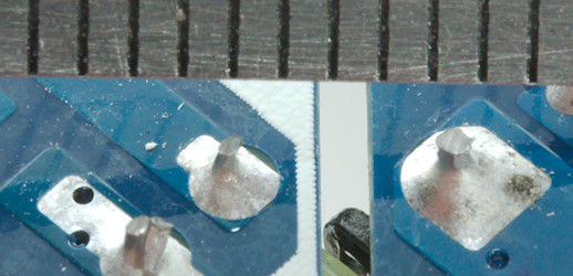
With a slot in the circuit board the distance only needs to be 4mm, here it is more like 2mm.
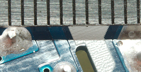
Outside the slots the distance must be around 6mm, here it is 4mm.
Testing with 2830 volt and 4242 volt between mains and low volt side, did not show any safety problems.
Conclusion
This QC charger works acceptable for QC2, but I had some trouble with adjusting the QC3 voltage down. I do have the auto coding on the USB connector. The safety is not up to regulatory standards, but it is not directly dangerous.
Notes
The charger was supplied by a reader for review.
Index of all tested USB power supplies/chargers
Read more about how I test USB power supplies/charger