RAVpower Bolt 4 port desktop RP-UC07
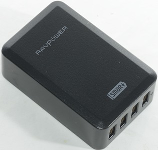
Official specifications:
- Power: 40W
- Input: 110-240V
- Output: DC 5V 8A
- Size: 59x91x29mm
- Weight: 147g
I got it on amazon.de from: Ravpower
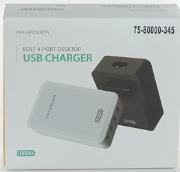
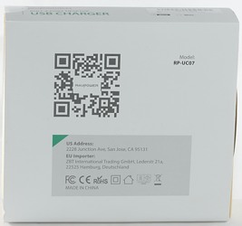
I get the charger in a retail box.
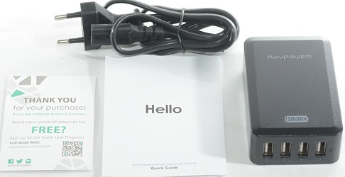
The box contained the charger, power cable, instruction sheet and a "Thank you" card.
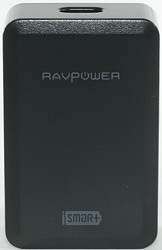
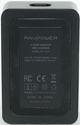
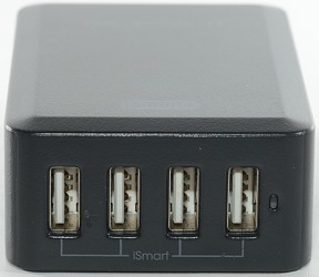
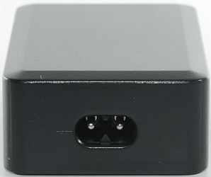
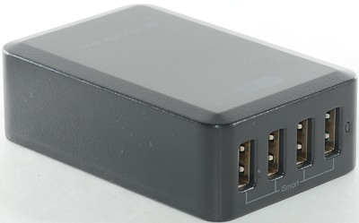
Measurements
- Power consumption when idle is 0.14 watt
- The indicator led is green.
- Port has automatic coding with Apple 2.4 as maximum.
- All outputs are in parallel.
- Size: 95x59x30mm
- Weight 157g
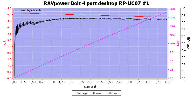
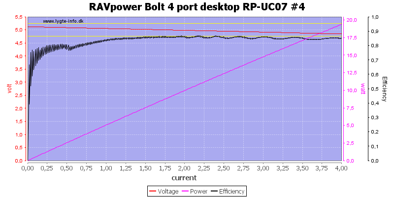
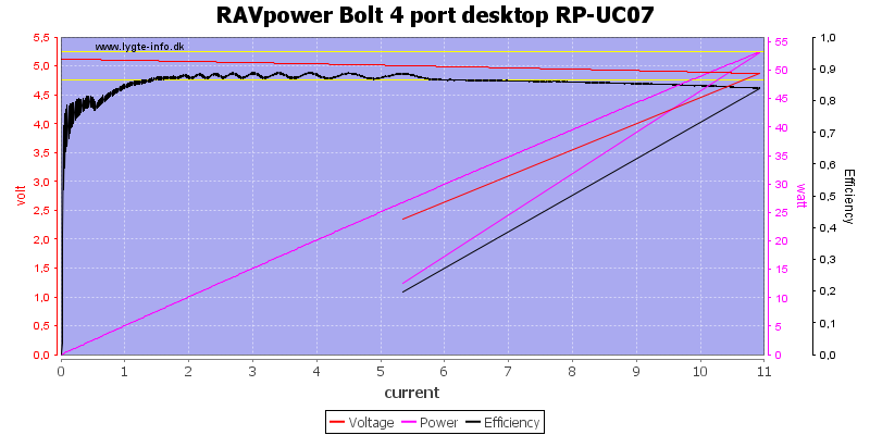
Each port is rated for 2.4A, but there is no individual overload protection. The common overload protection is just below 11A, this looks very reasonable.
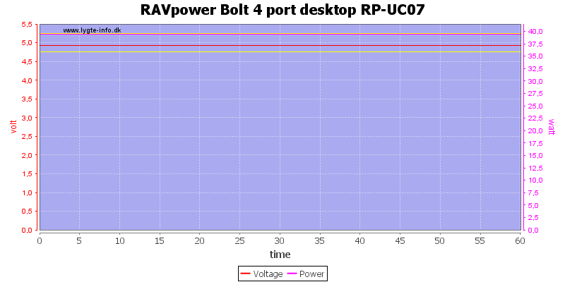
There is no problem running at full 8A load for one hour.
The temperature photos below are taken between 30 minutes and 60 minutes into the one hour test.
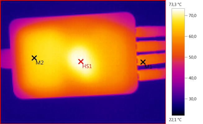
M1: 56,4°C, M2: 65,8°C, HS1: 73,3°C
HS1 is the transformer and M2 is the heatsink for the mains switcher transistor.
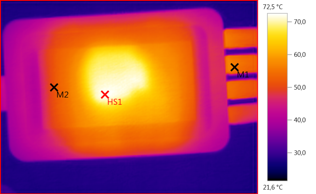
M1: 55,7°C, M2: 51,2°C, HS1: 72,5°C
On the bottom HS1 is also the transformer.
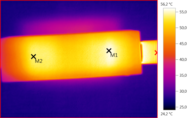
M1: 55,6°C, M2: 53,4°C, HS1: 56,2°C
M2 is the mains switcher transistor and M1 is the rectifier.
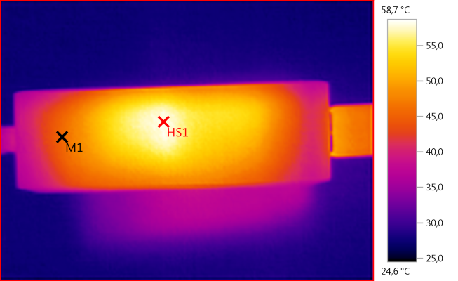
M1: 45,8°C, HS1: 58,7°C
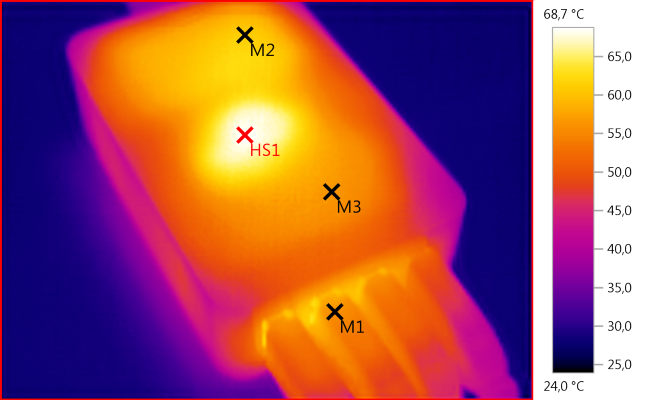
M1: 55,9°C, M2: 61,2°C, M3: 56,7°C, HS1: 68,7°C

Noise at 0.5A load is: 10mV rms and 210mVpp.

Noise at 1A load is: 10mV rms and 150mVpp.

Noise at 2.5A load is: 8mV rms and 79mVpp.
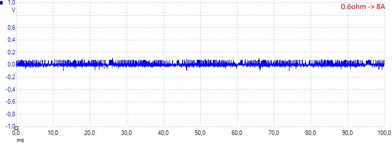
Noise at full load is: 22mV rms and 220mVpp.
Tear down
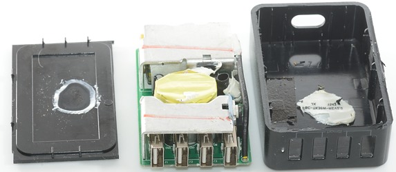
I could not break this charger open, but had to cut it and then break it (The white stuff was holding it together).
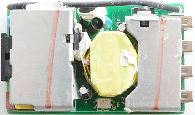
A lot of the circuit is hidden by the two heatsinks, but some stuff can be seen. The mains switcher transistor is mounted on one of the heatsink and the rectifier on the other. There are 3 blue safety capacitors, two of them connected by a wire.
The optocoupler is placed beside the transformer (OP1).
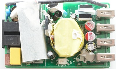
Removing the heatsinks makes it easier to see, but some of it are still hiding below a piece of paper (for isolation).
It looks like the output rectifications is a FET and a diode.
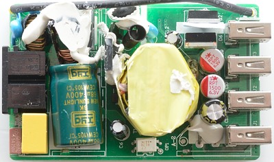
Now it is easier to see the input circuit with a fuse, two common mode coils and a bridge rectifier.
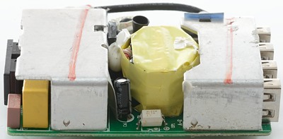
From this side only the heatsink, fuse and the optocoupler can be seen
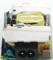
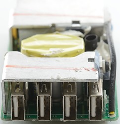
From the end one of the safety capacitors can be seen and the fuse.
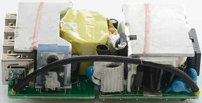
The led is mounted on a small circuit board beside the usb connectors. The wire connecting output with two of the safety capacitors are on this side (It has two layers isolation).
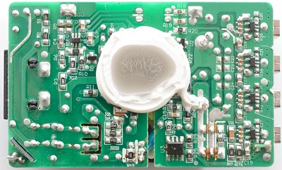
On the bottom are a big blop of white stuff to transfer heat to the case. There is also the mains switcher controller (U1), A chip to control the synchronous rectifier (U3), the voltage control (U2) and the auto coding chips (U4, U5, U6, U7).
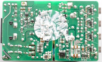
I wanted to see if there was something hidden under the white stuff, but it did not look like it.
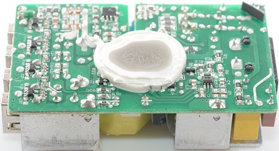

Safety distance is good.
Testing with 2500 volt and 5000 volt between mains and low volt side, did not show any safety problems.
Conclusion
The charger is a very good usb charger with lots of power.
Notes
Index of all tested USB power supplies/chargers
Read more about how I test USB power supplies/charger


