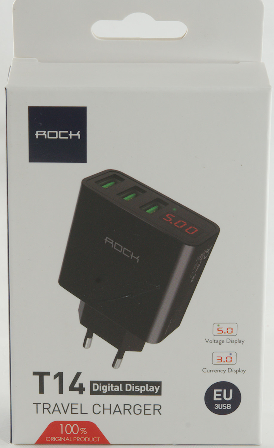
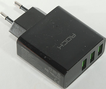
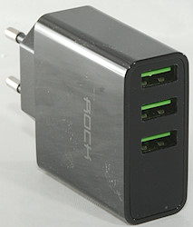
Roch T14 3 port Travel Adapter
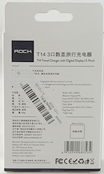
Official specifications:
- Brand: Rock
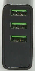
- USB Port: 3 USB Ports
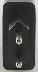
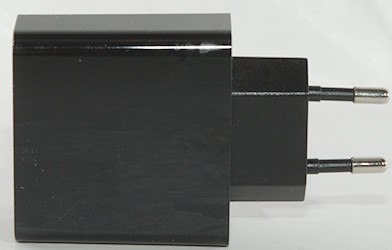
- Plug: EU Plug
- Dimensions: 65.7*52.1*24mm
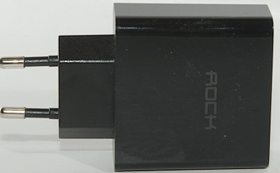
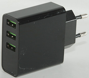
- Color: Black, White
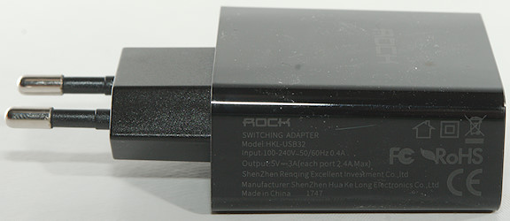
- Input: 100-240V/0.3A
- Output: 5V/3A(max)
- Certification: CCC,FCC,CE,RoHS
I got it from banggood

I got it in a cardboard box.
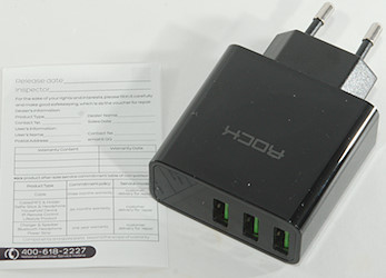
The box included the charger and a warranty card.
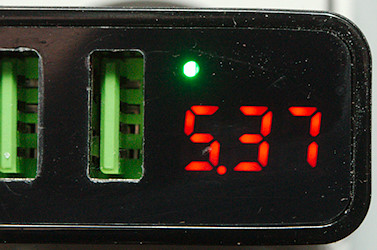
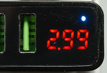
Voltage and current display. Voltage display will only be shown at the start and end, not while it is charging a device.
Measurements
- Power consumption when idle is 0.11 watt (Display turns off to get this low power consumption)
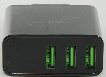
- Output #1 is usb coded (DCP).
- Outputs #2 & #3 are auto coding with Apple 2.4A as maximum.
- Outputs are in parallel.
- Display turns on at about 0.22A and off when current drops to about 0.07A
- Size: 86.5 x 52.0 x 24.0 mm
- Weight: 63.5 g
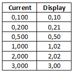
Current display is very precise, but it will drift a bit with temperature (After 15 minutes 3.00 increased to 3.03).
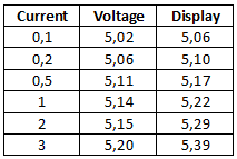
Voltage display is not as good. To get the real voltage I measured voltage on one usb connector and put the load on another usb connector. The result did not change much when I tried different connectors.
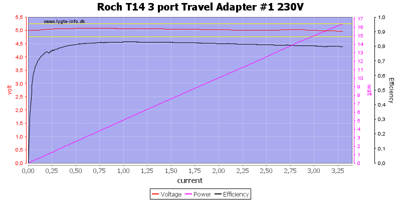
The charger can deliver about 3.25A on output #1, before overload trips.
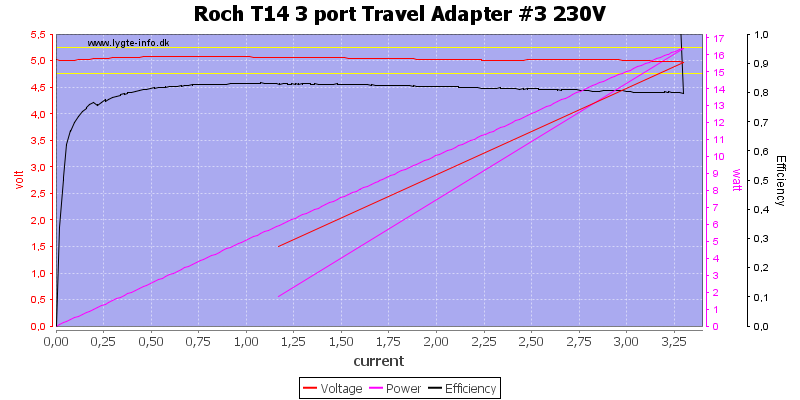
The same on output #3
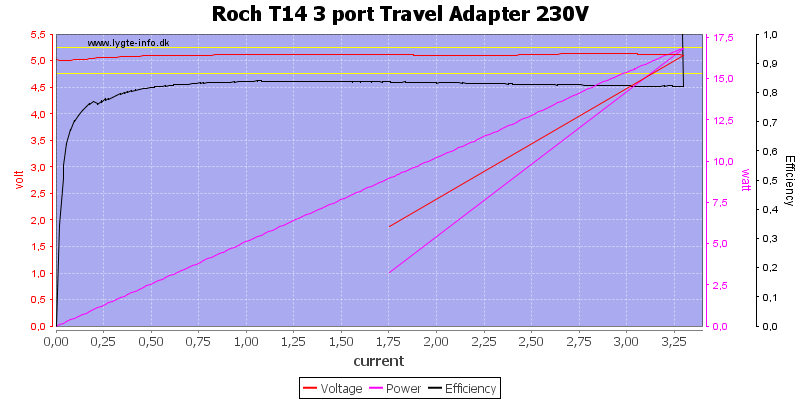
And also with all outputs in parallel.
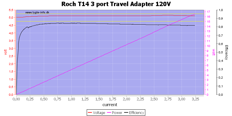
It is about the same as 120VAC.
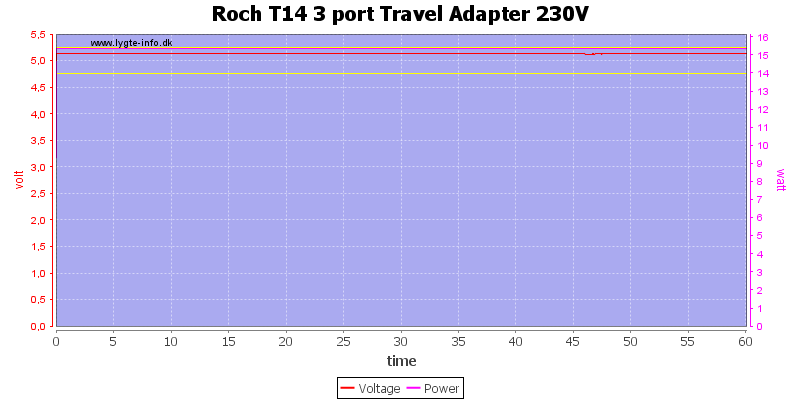
Running one hour at 3A was no problem.
The temperature photos below are taken between 30 minutes and 60 minutes into the one hour test.
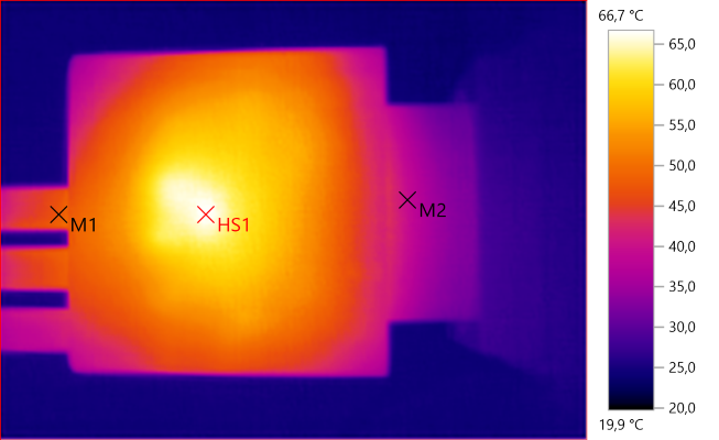
M1: 47,8°C, M2: 39,5°C, HS1: 66,7°C
HS1 is the rectifier chip.
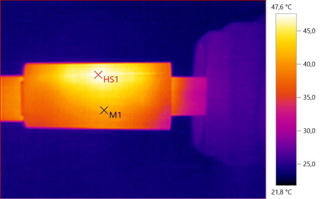
M1: 41,4°C, HS1: 47,6°C
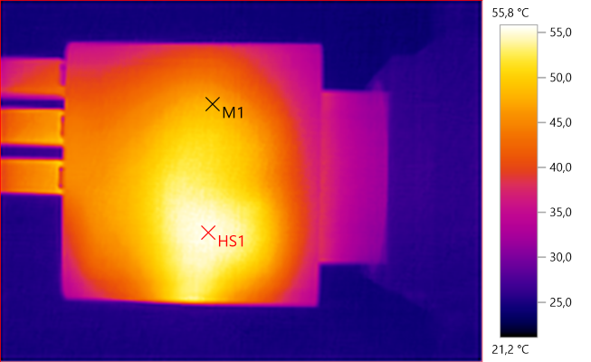
M1: 47,9°C, HS1: 55,8°C
HS1 is the transformer.
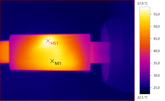
M1: 54,1°C, HS1: 57,9°C
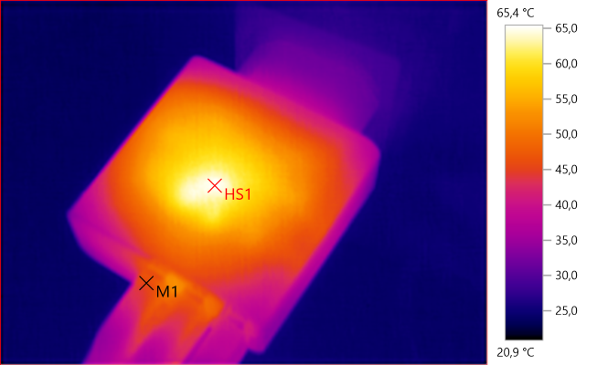
M1: 45,7°C, HS1: 65,4°C
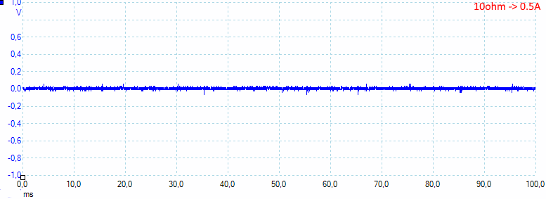
At 0.5A the noise is 11mV rms and 113mVpp.
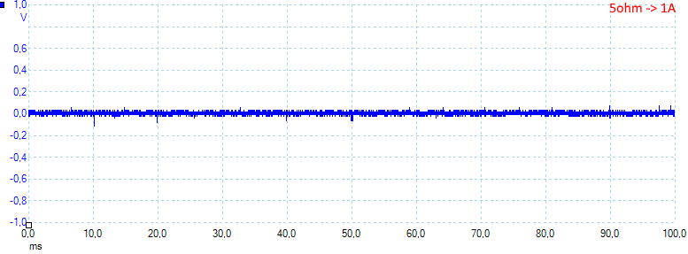
At 1A the noise is 16mV rms and 113mVpp.
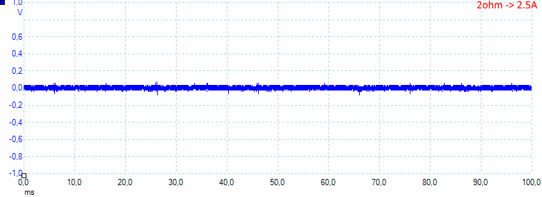
At 2.5A the noise is 22mV rms and 111mVpp, this is very low noise numbers.
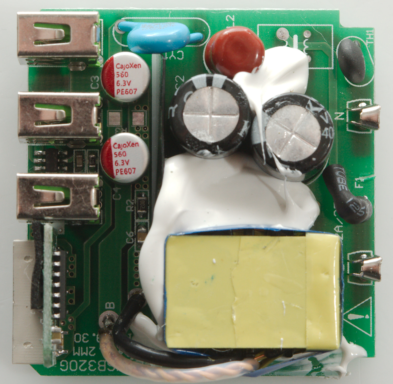
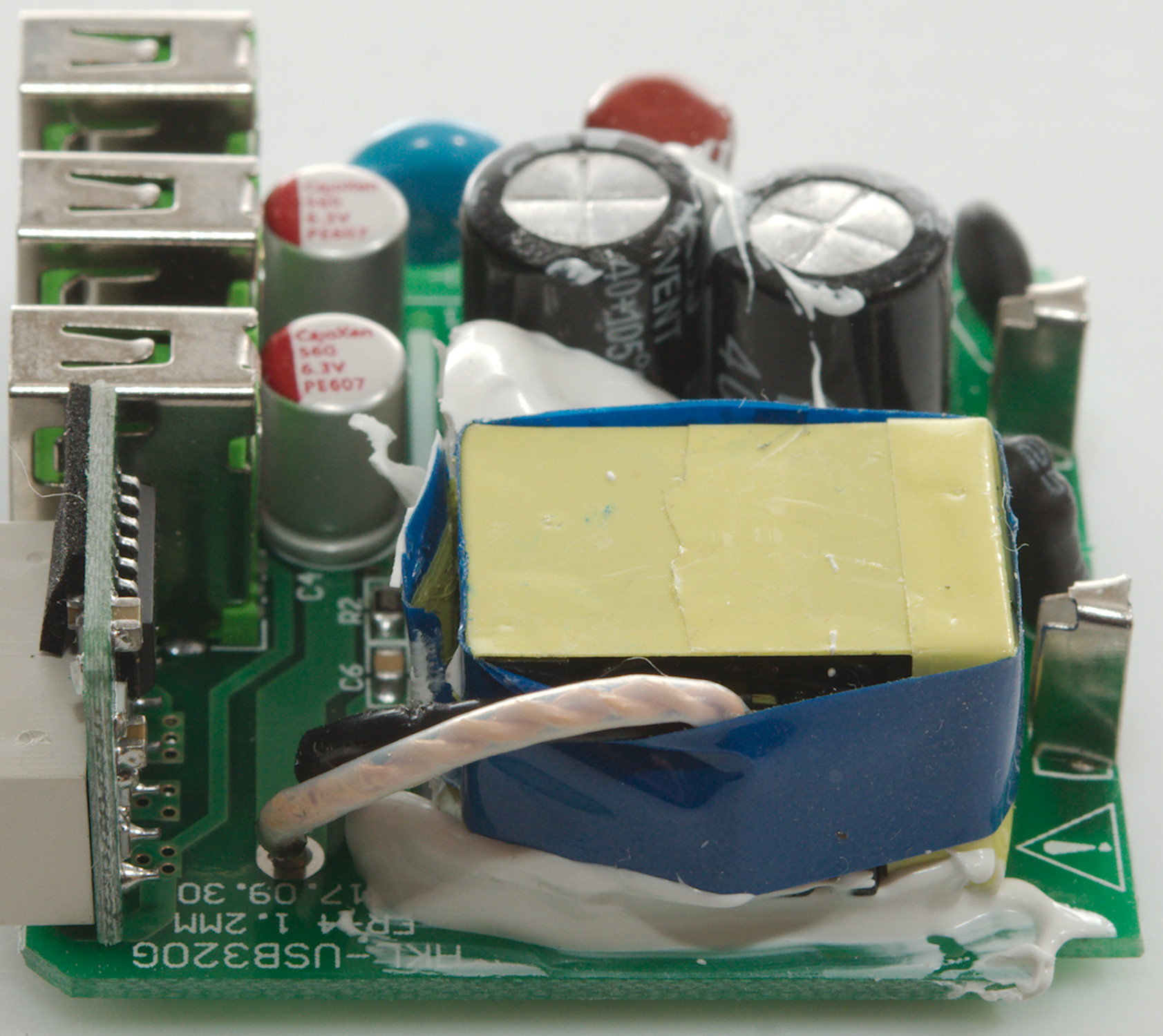
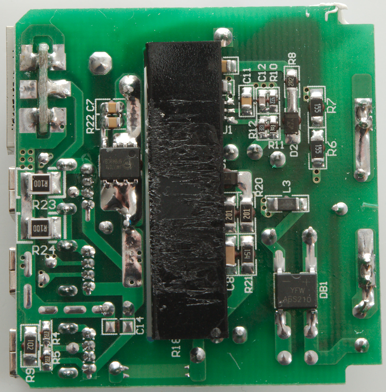
Tear down
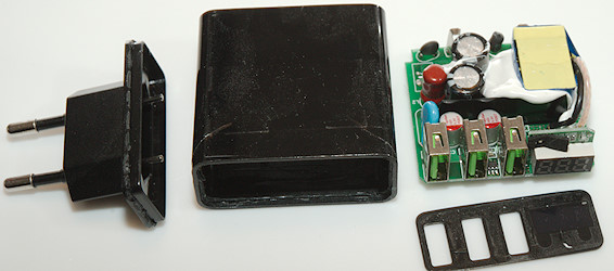
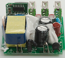
Some pressure with the vice and a few whacks with my mallet and it was open.

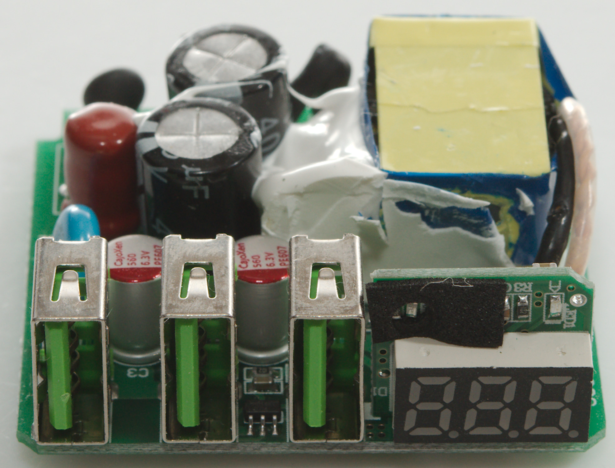
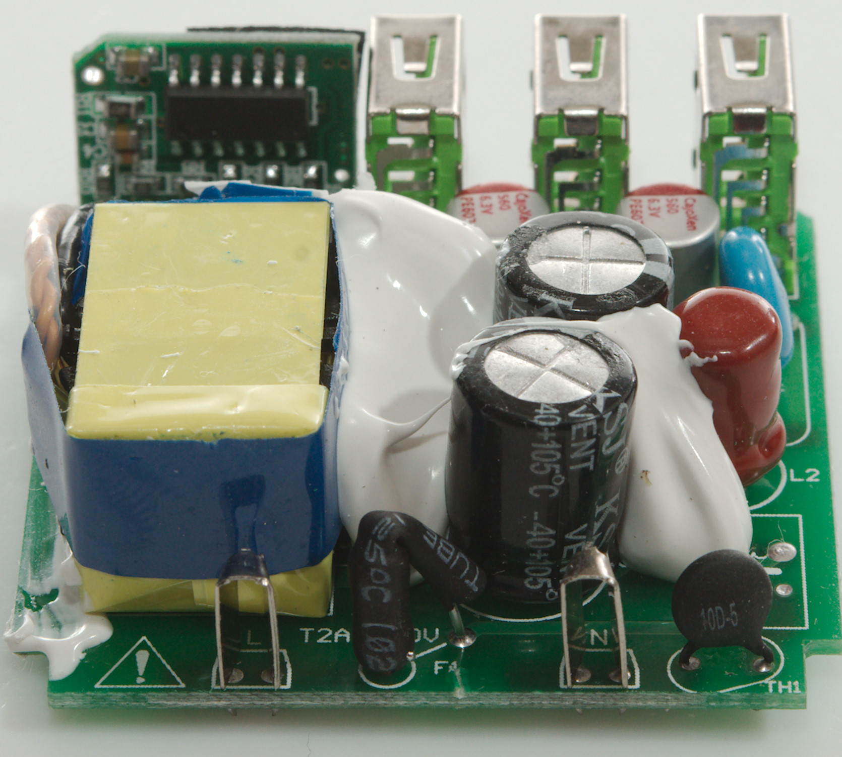
On this side is a fuse (F1) between the mains input connectors and a inrush current limiter (TH1: NTC). The common mode coil is left out, but there is a inductor (L2) between the two mains capacitors. The safety capacitor (CY1) is close to that.
The auto coding chip (PC5889) is between two usb connectors.
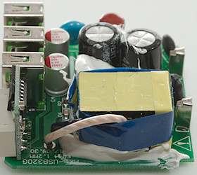
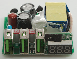
The display is on its own circuit board
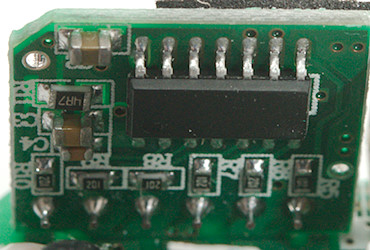
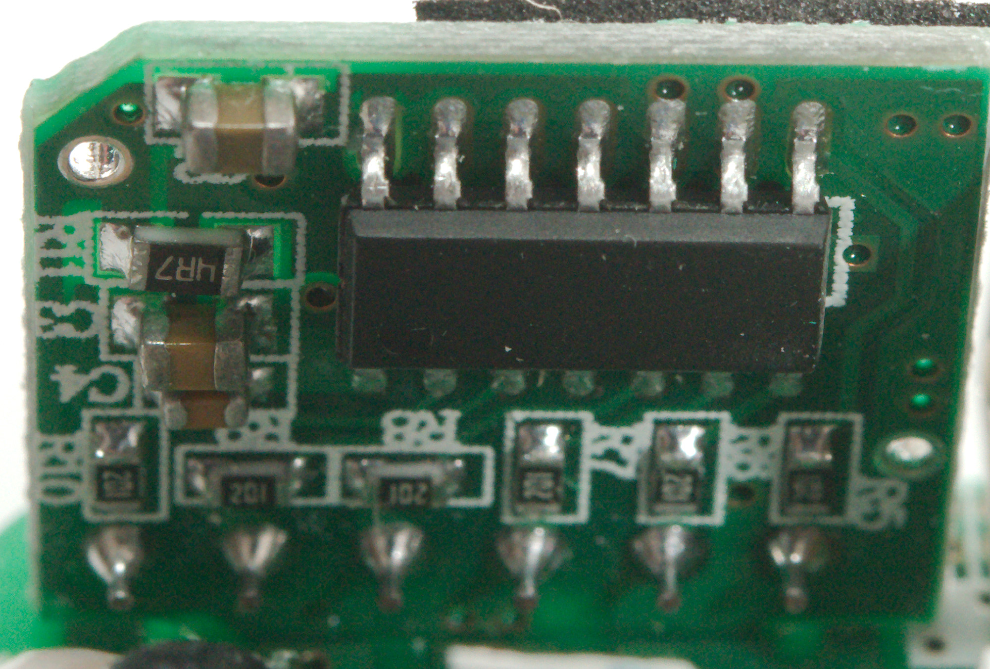
The voltmeter and ammeter is done by an unmarked chip.
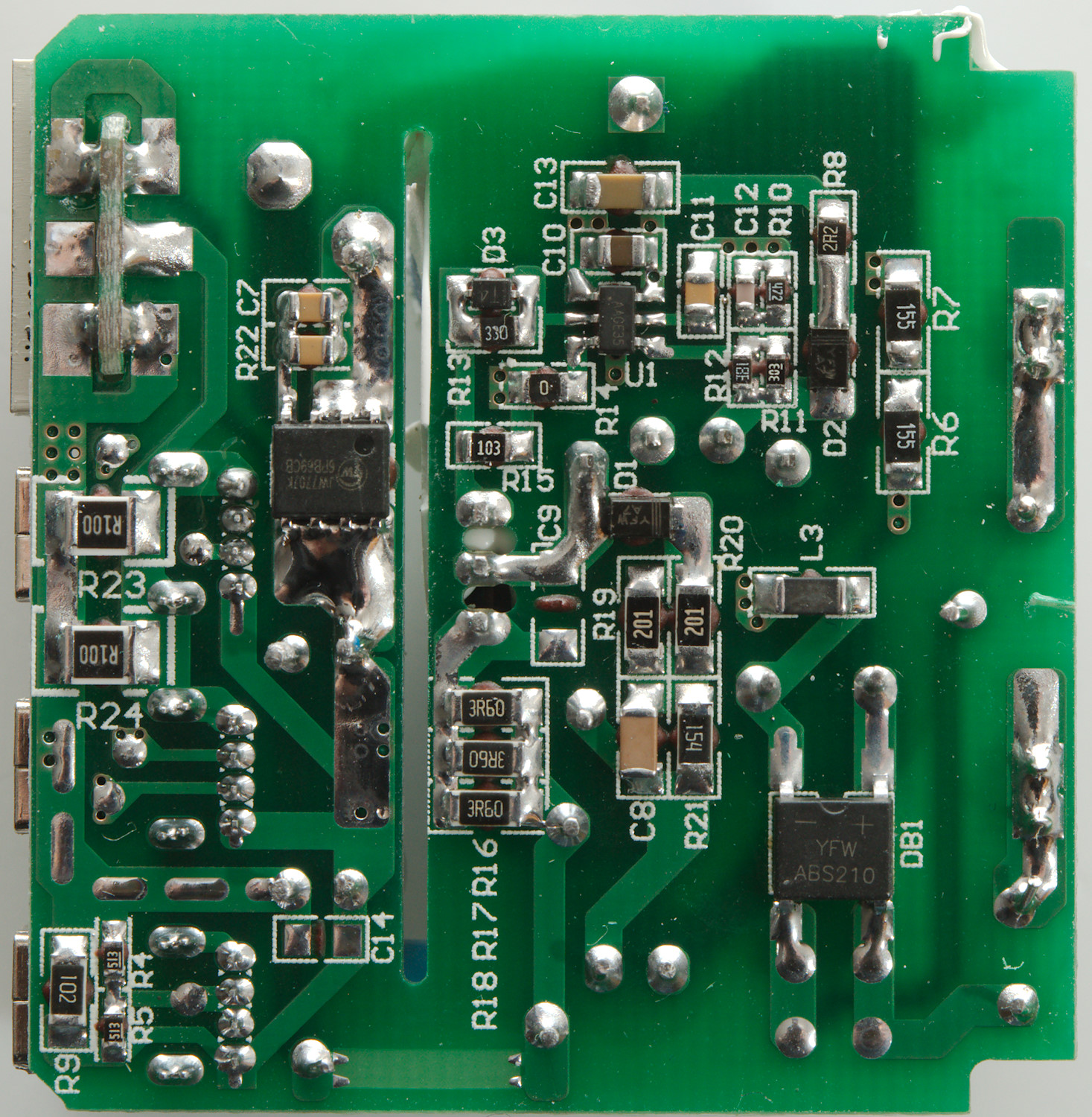
There is an isolation slot in the circuit board with some black plastic in it, this secures very good isolation distance.
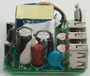
At the input is a bridge rectifier (DB1) and a SMD inductor (L3) to remove some noise. The switcher controller (U1: Marked AAGE35) is a small chip and it needs a switcher transistor, it is hidden in the white stuff on the other side, but the connections can be seen very close to R15/C9.
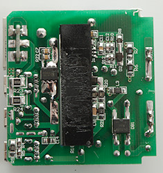
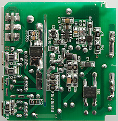
On the low volt side is a synchronous rectifier chip (JW7707K). There is two resistors in parallel (R23 & R24 0.1ohm) for measuring the output current (My guess is that the voltage is measured before these resistors and that is the reason for the high readings).
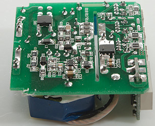
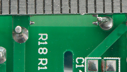
The isolation distance is very good.
Testing with 2830 volt and 4242 volt between mains and low volt side, did not show any safety problems.
Conclusion
The charger works fine with low noise, stable output voltage and auto coding (On two connectors) and has a display showing the current with good precision. I did not see any safety problems.
BUT with only 3A for 3 connectors it is very weak, no marking on ports about auto detect or not and the build-in voltmeter is not very precise.
I will rate it as a good charger, but it is best used for one or two devices, not for 3.
Notes
Index of all tested USB power supplies/chargers
Read more about how I test USB power supplies/charger
How does a usb charger work?