Roidmi Smart Car Charger 3S BFQ04RM
Official specifications:
- Brand: ROIDMI
- Model: 3S
- Color: Black
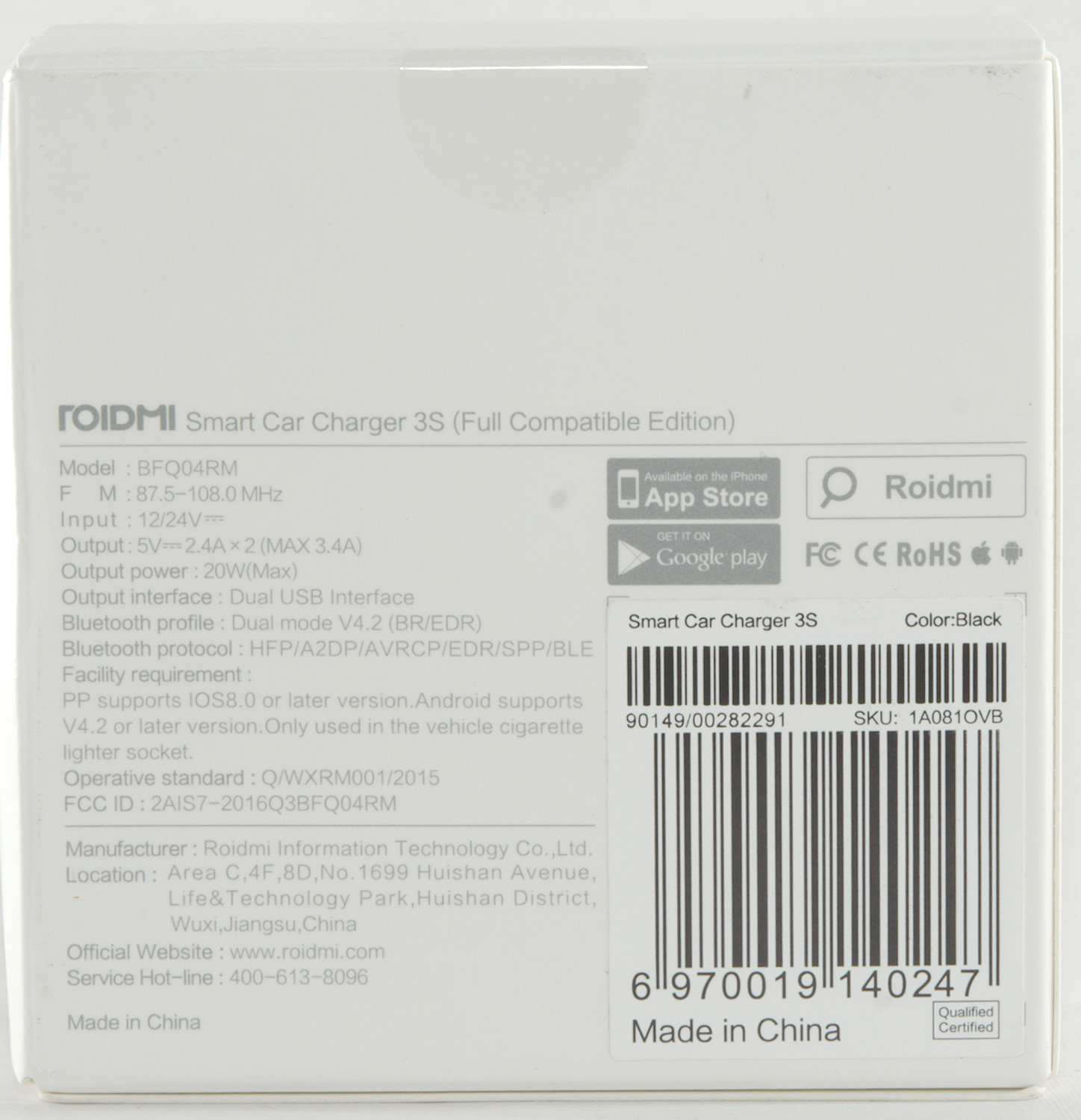
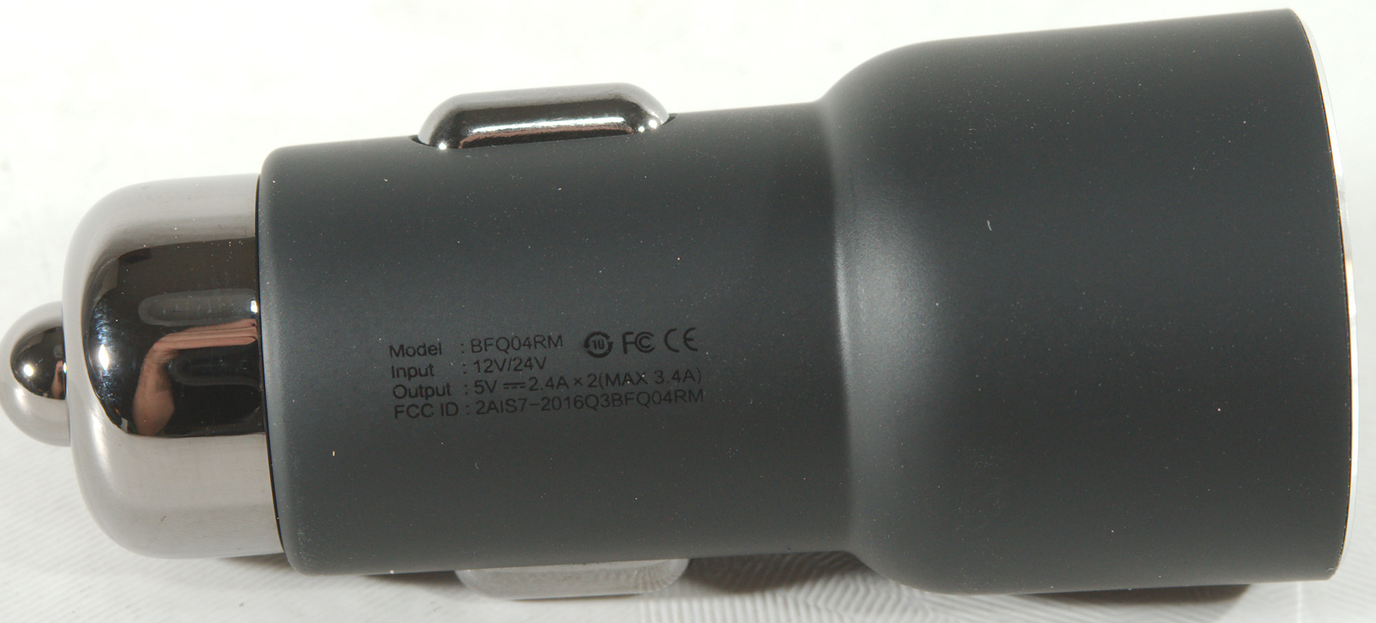
- Input (Car Charger): 12 - 24V
- Output (Car Charger): 5V 2.4A ( Max. 3.4A ) / 5V 2.4A ( Max. 3.4A )
- Apply To Car Brand: Universal
- Working Temp.: 10 - 60 Deg.C
- Material (Cable & Adapter): Stainless Steel
- FM frequency: 87.5 - 108.0MHz
- Bluetooth profile: Dual mode V4.2 (BR/EDR)
- Bluetooth protocol: HFP/A2DP/AVRCP/EDR/SPP/BLE
I got it from gearbest.com
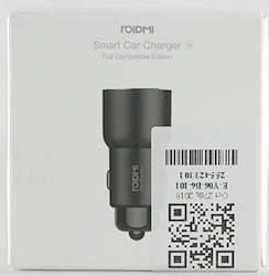
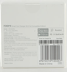
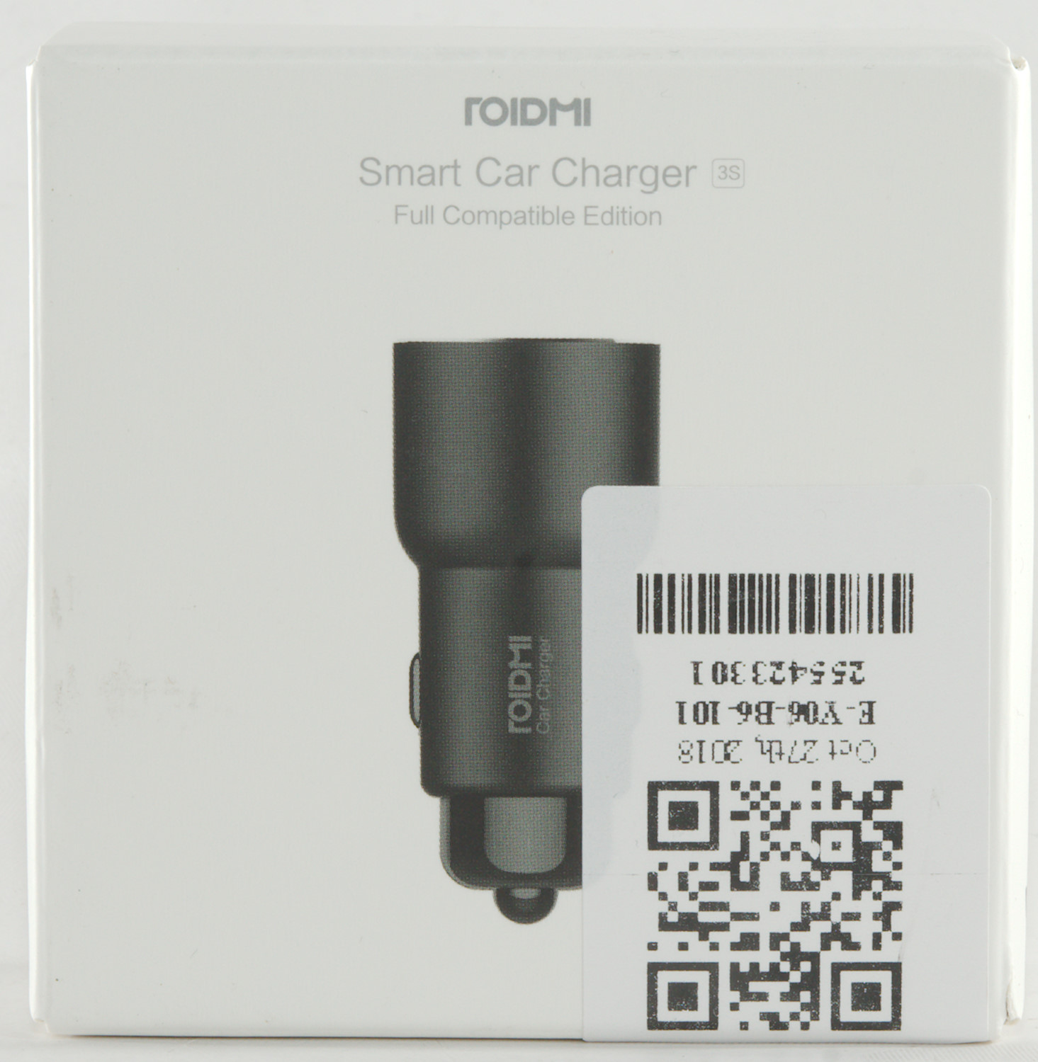
It arrived in a white box with specifications on the back.
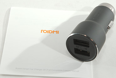
In the box was the charger and a instruction sheet.
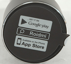
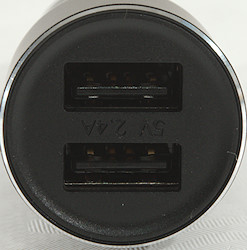
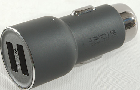
When I unpacked it there was a label telling about the control application. Below it was the two usb connectors and a very discrete 5V 2.4A marking.

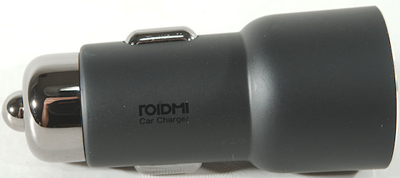
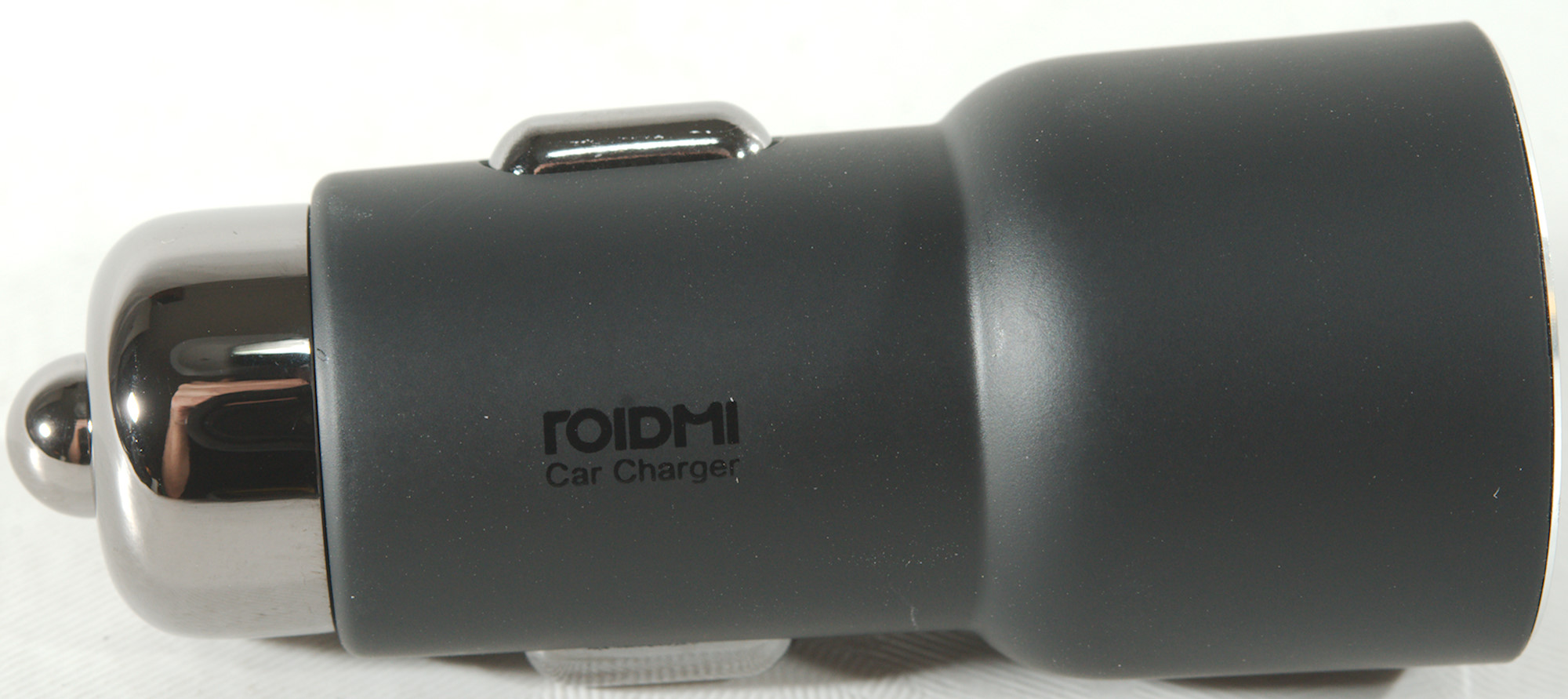
The markings on the charger is also very discrete being black print on a black charger.
Measurements
- Usb ports are coded with Apple 2.4A, Samsung, DCP, QC 5V
- Power consumption when idle is 60mA from 12V and 45mA from 24V
- There is a cyan led behind the usb connectors, it will flash when on and be steady when Bluetooth is connected.
- The led probably has other colors, the tear down showed a RGB led controller chip.
- Weight: 31.2g
- Length: 61mm
- Front: Ø26.3mm

Overload protection is slightly above 2.5A, this is very good for a 2.4A charger.
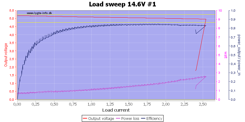
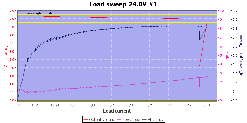
Voltage do not really change output voltage or overload protection.
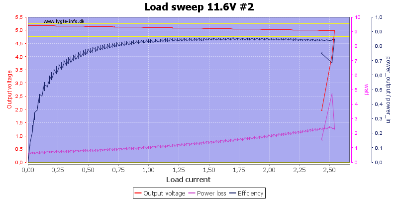
The second output has the same limit.
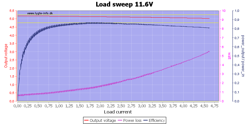
But when used together the output is much higher and well above the rated 3.4A
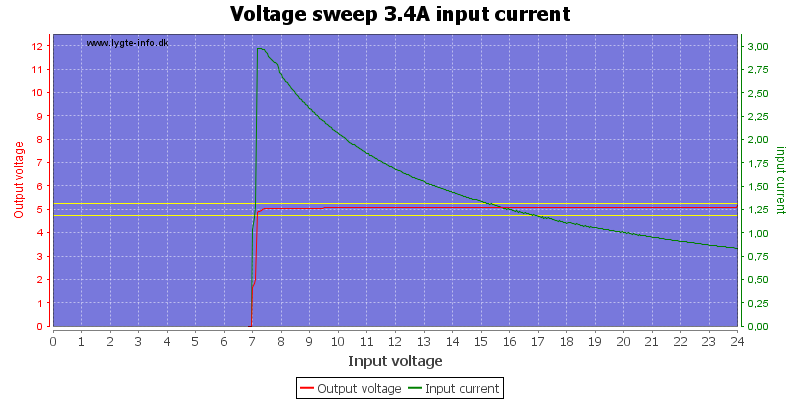
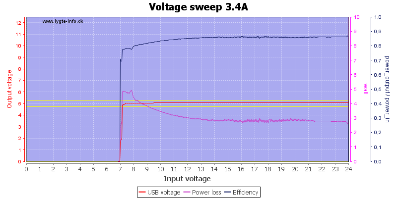
The charger works down to about 7V
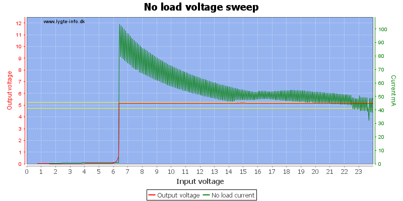
The idle current is fairly high due to Bluetooth and FM transmitter.
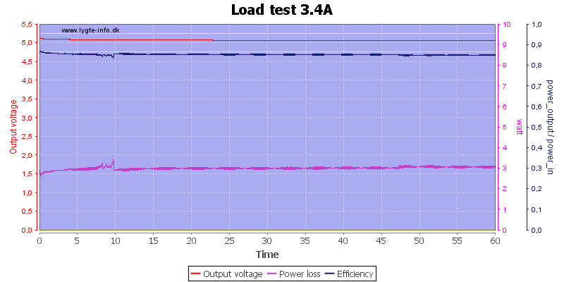
There was no problem running 1 hour with 3.4A load.
The temperature photos below are taken between 30 minutes and 60 minutes into the one hour test.
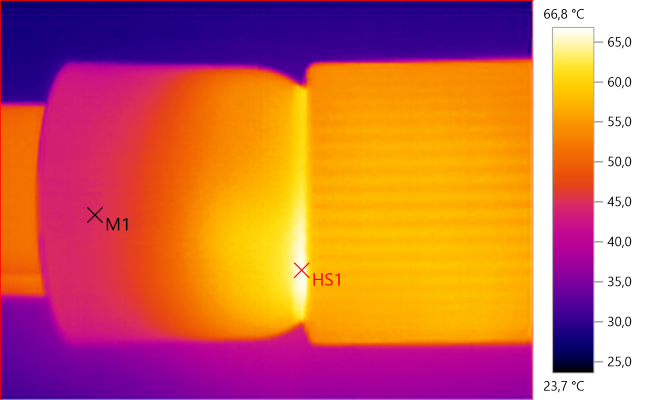
M1: 44.7°C, HS1: 66.8°C
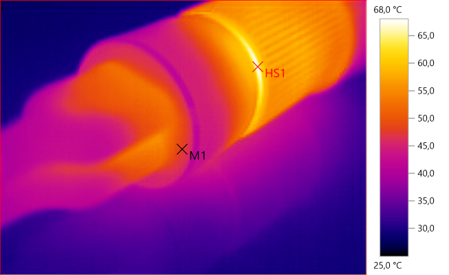
M1: 48.0°C, HS1: 68.0°C
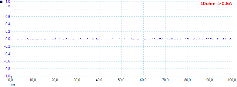
At 0.5A the noise is 3mV rms and 50mVpp.
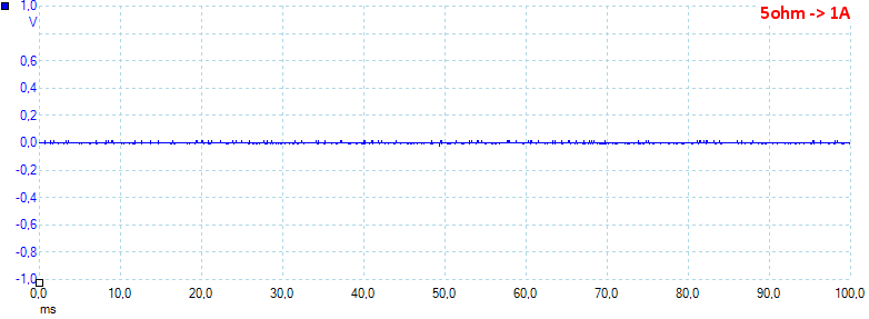
At 1A the noise is 3mV rms and 52mVpp.

At 2.5A the noise is 6mV rms and 67mVpp.
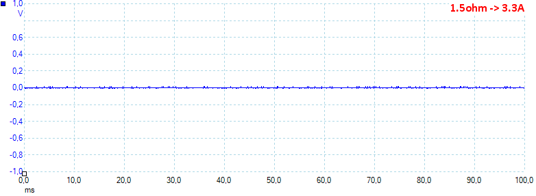
At 3.3A the noise is 3mV rms and 55mVpp, all very very low values.
Bluetooth & FM
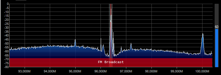
The FM radio is at selected frequency.
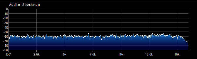
And white noise shows a horizontal level as it is supposed to do.

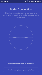
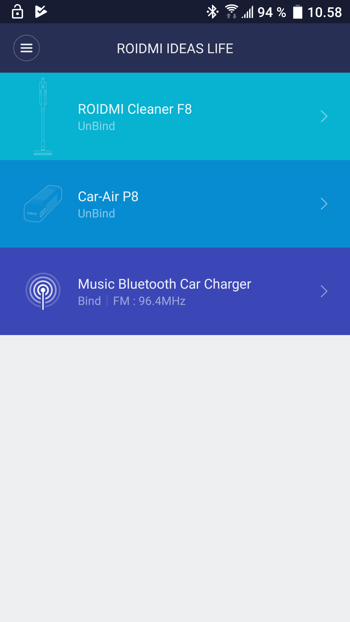
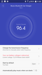
Roidmi has more than one Bluetooth product and they all share the same application, here I selected "Music Bluetooth Car Charger" and got a couple of simple setup screens. The application did require a lot of access to the phone: Phone, location, pictures, etc.
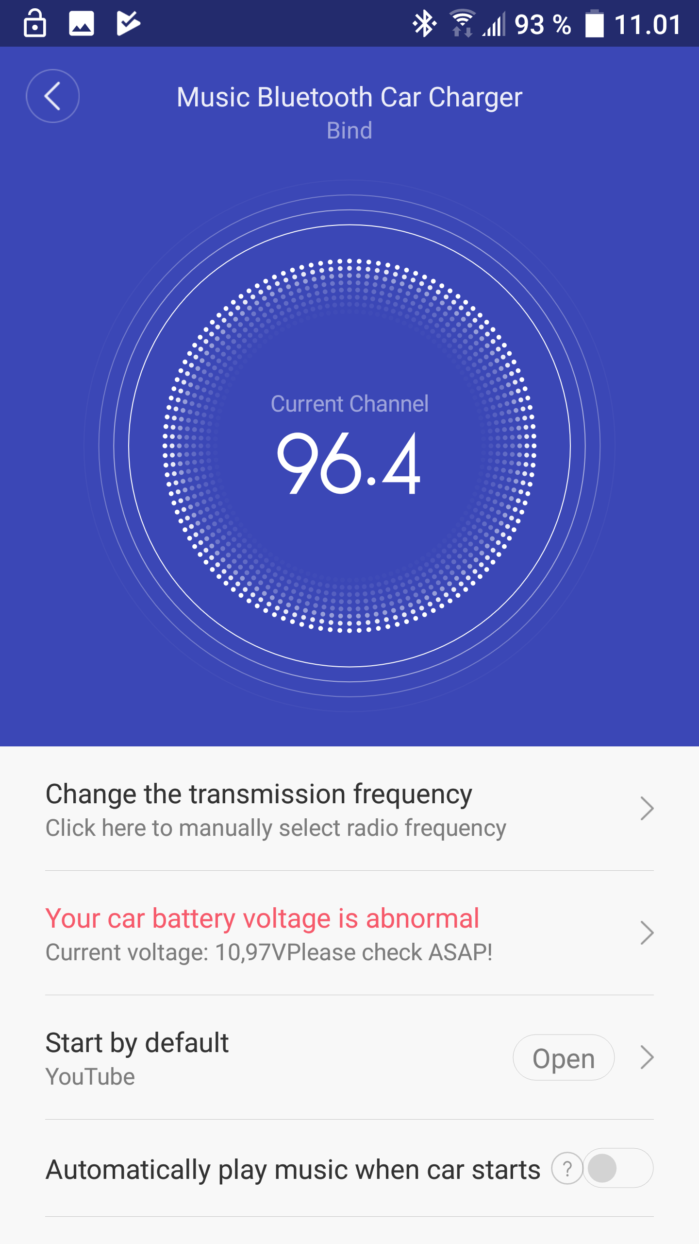
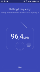
This application is not required to use the charger, the charger will connect to the phone and play music on 96.4MHz without it. The application is required to change FM frequency or read the battery voltage.
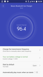
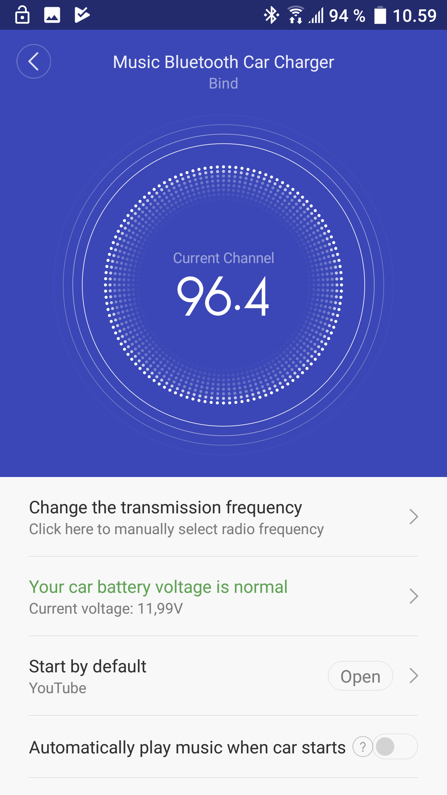
This is the default screen for the charger.
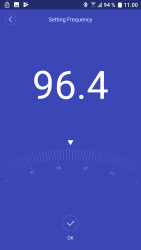
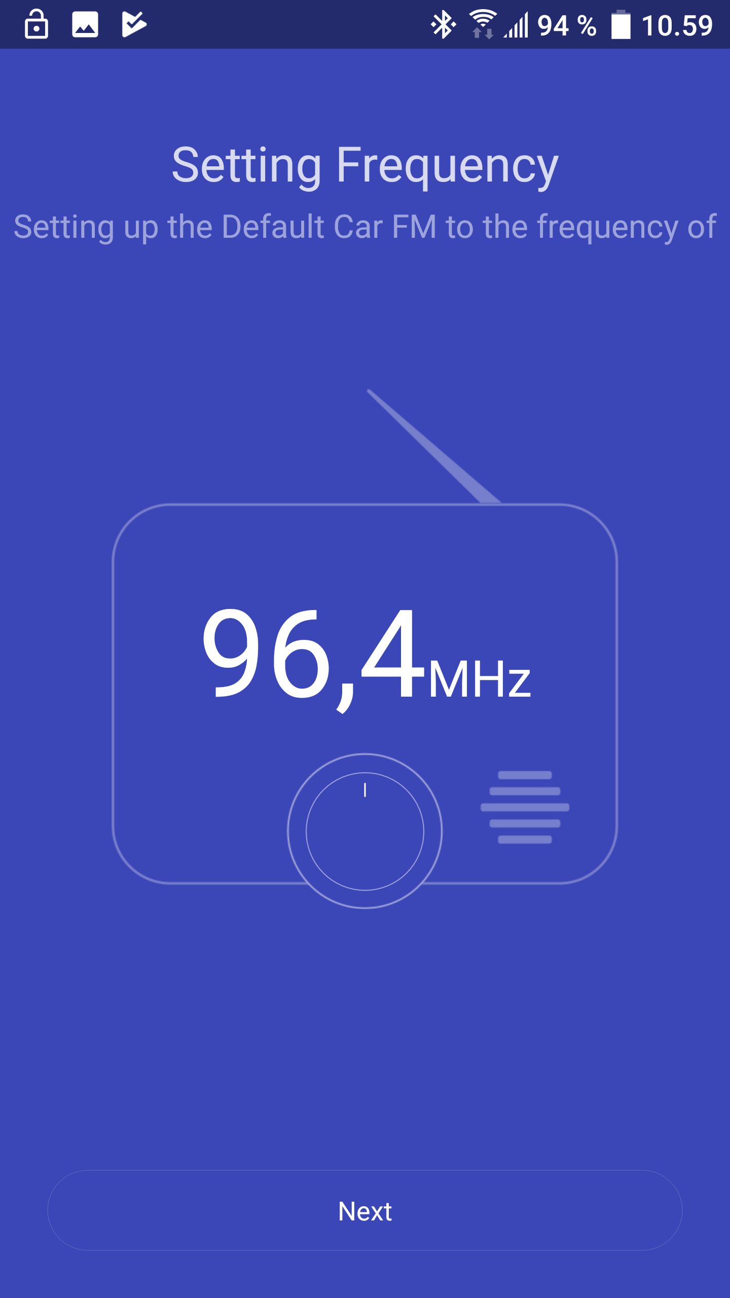
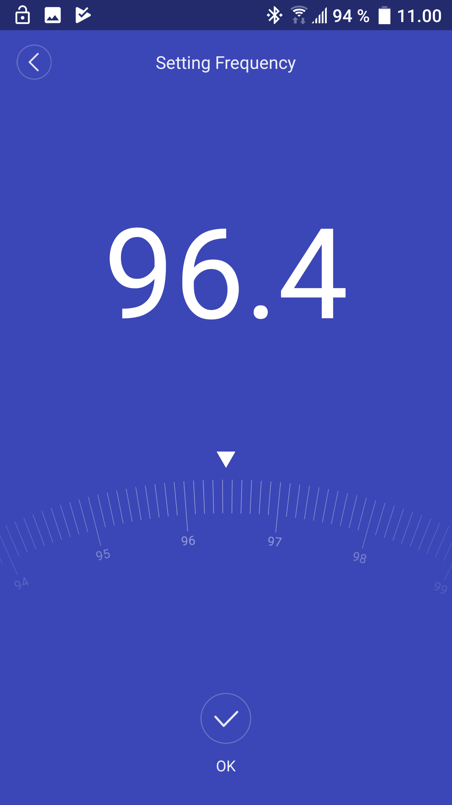
The frequency select looks similar to the initial frequency select.

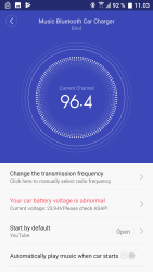
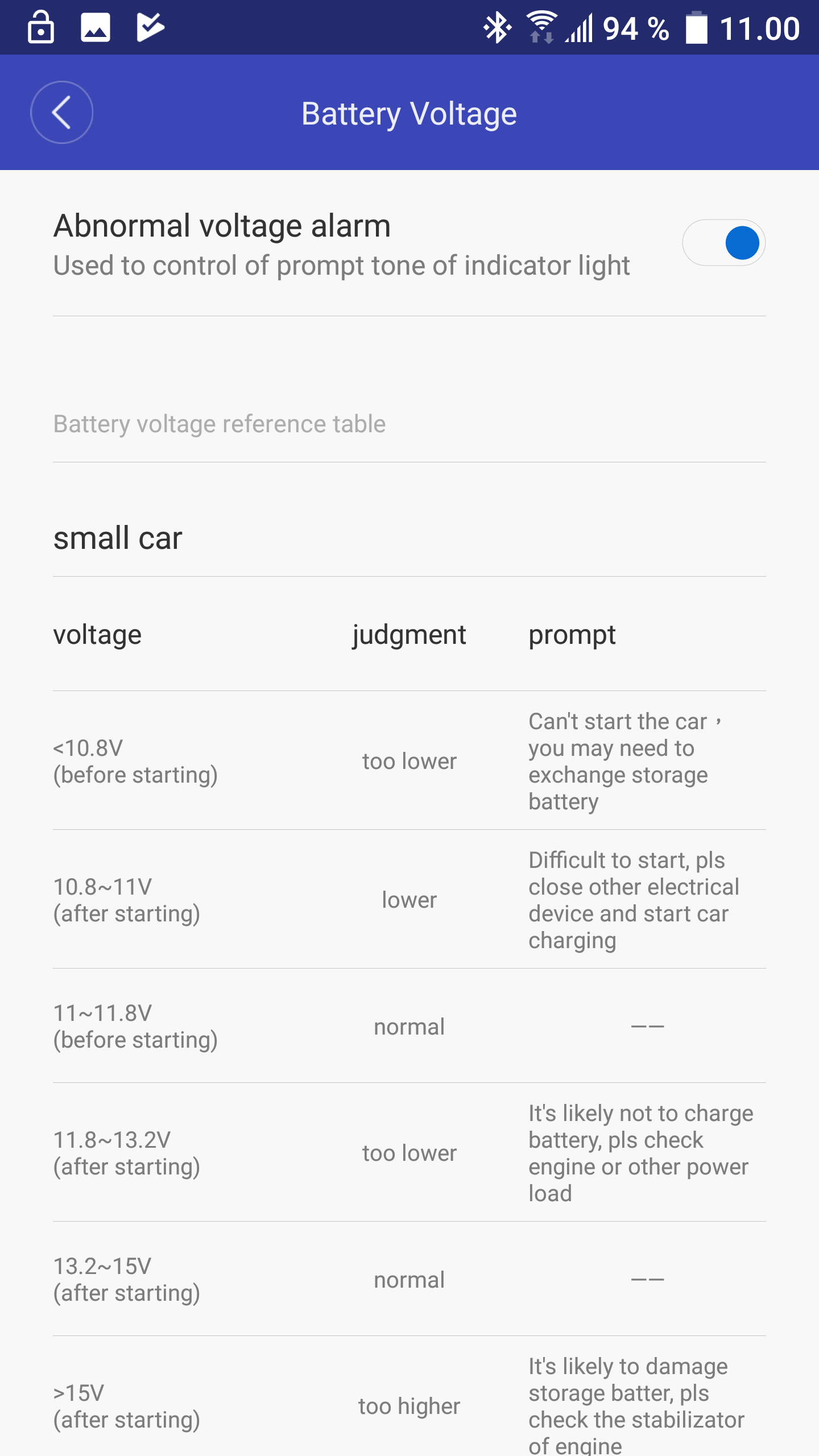
The voltage display will give an alarm when battery voltage is out of tolerances. It is fairly precise, 12V is shown as 11.997V and 24V is shown as 23.94V. It cannot measure all voltage, but only the valid range for 12V and 24V batteries.

It also includes an explanation of the different voltage ranges for a car.

The about information is missing. This screen was selected on the welcome screen.
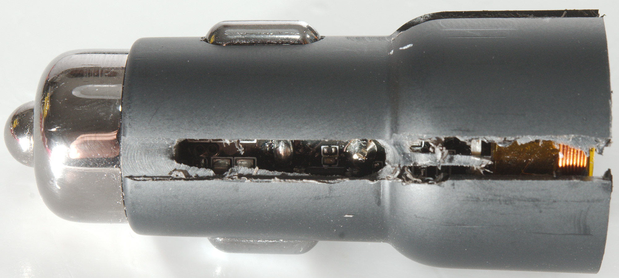
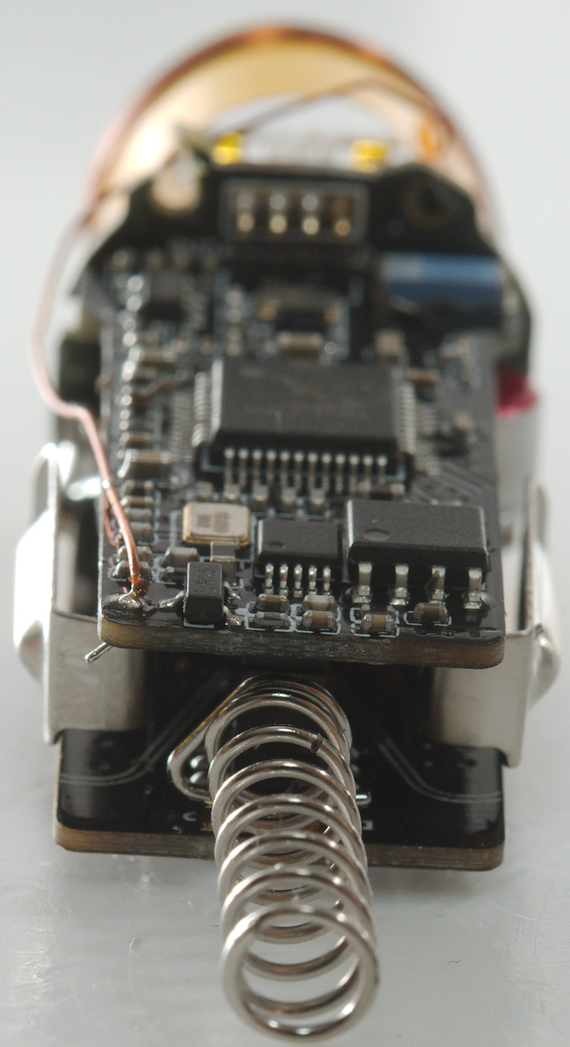
Tear down
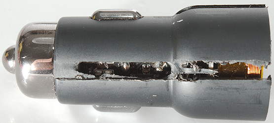
I could not get it open and used some dramatic cutting to do it.
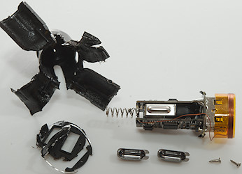
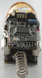
When I got it open I could see it was assembled from the front with two small screws to hold the electronic in place. The screws is first accessible when the front is removed.
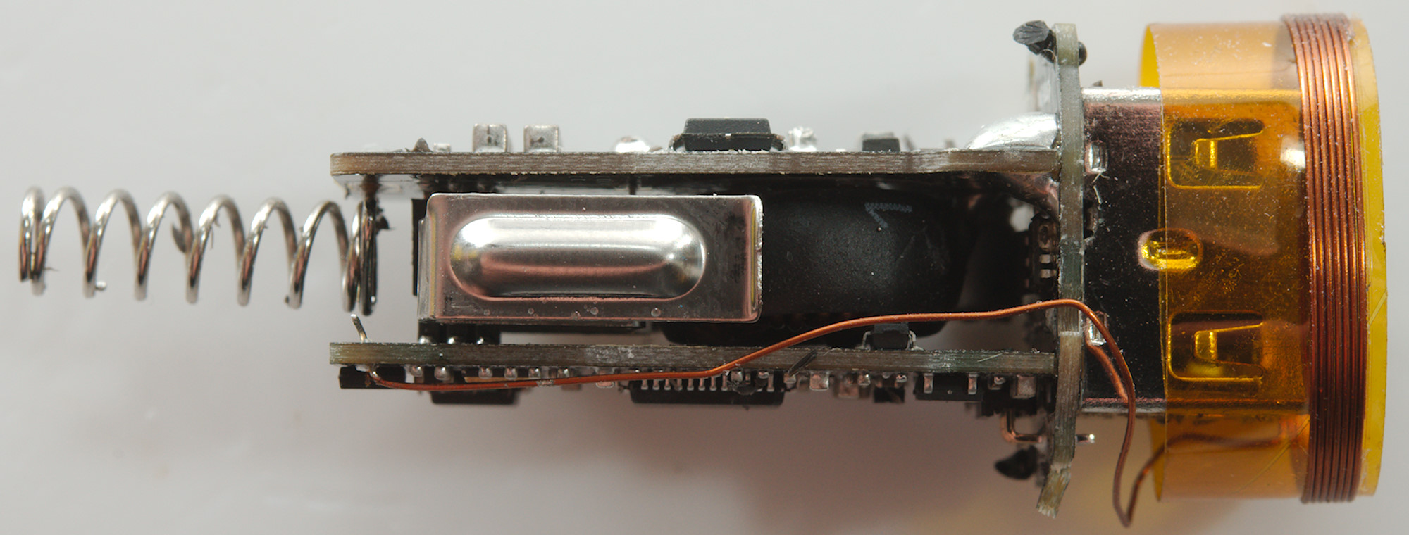
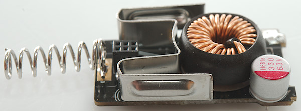
The construction is two layer, one is radio, the other power supply. The front do also have some parts.

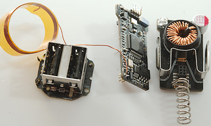
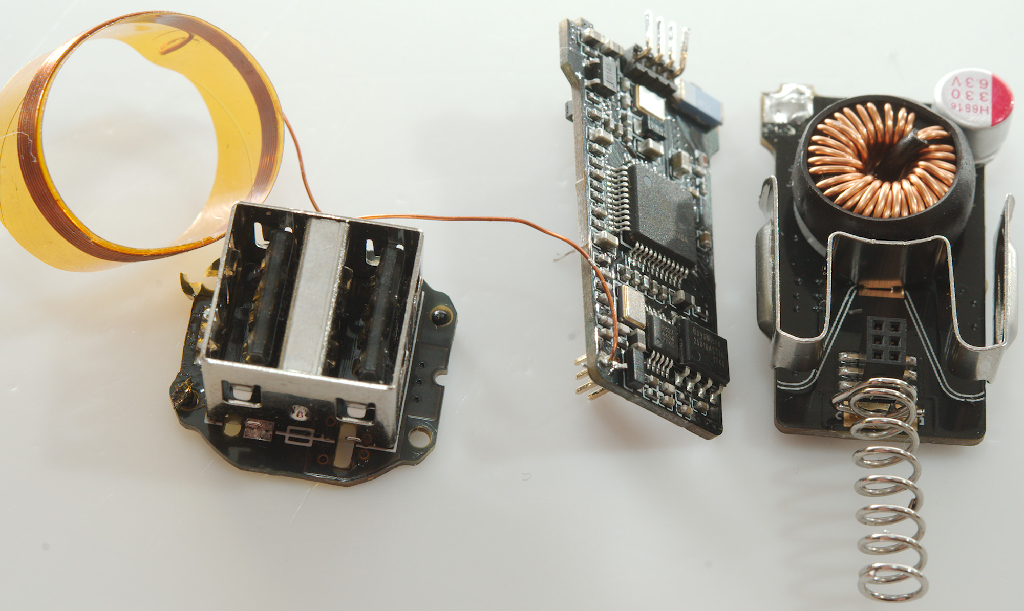
Some soldering and the two layers was apart.
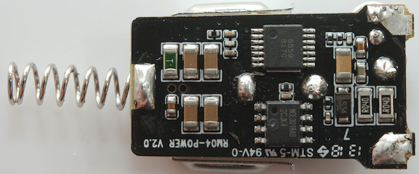
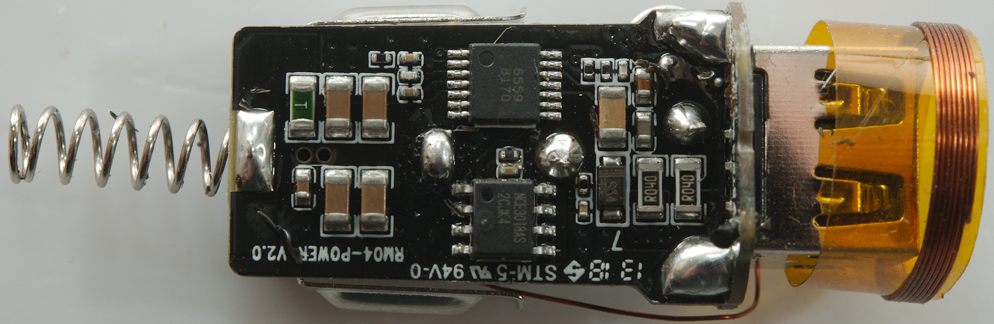
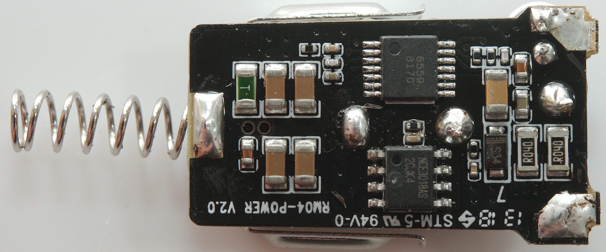
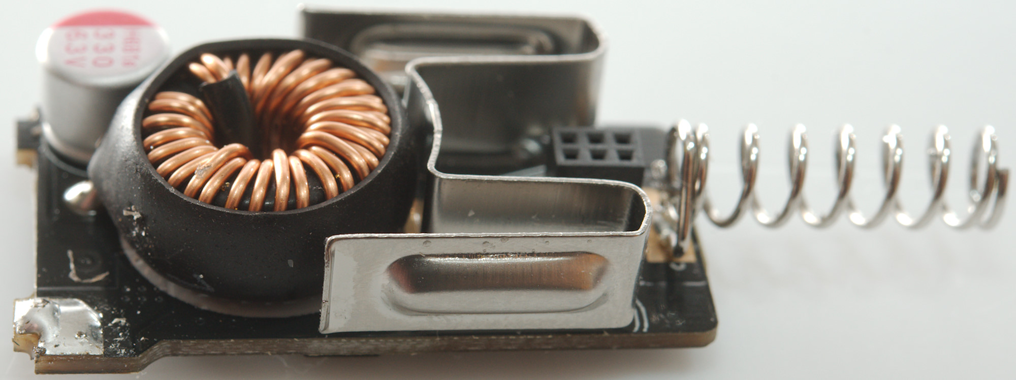
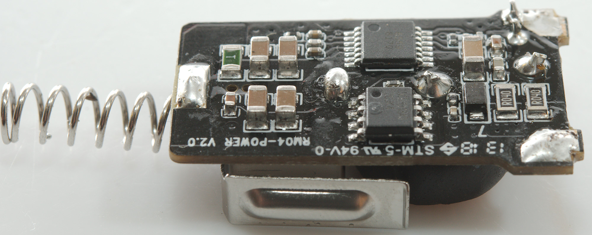
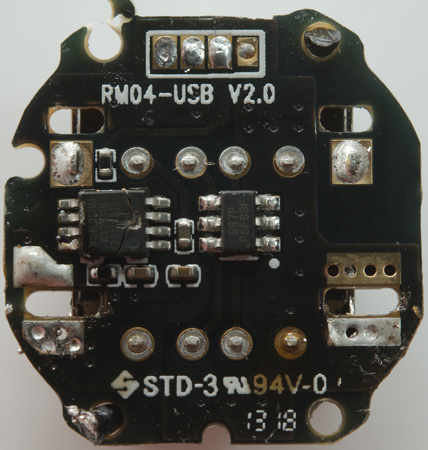
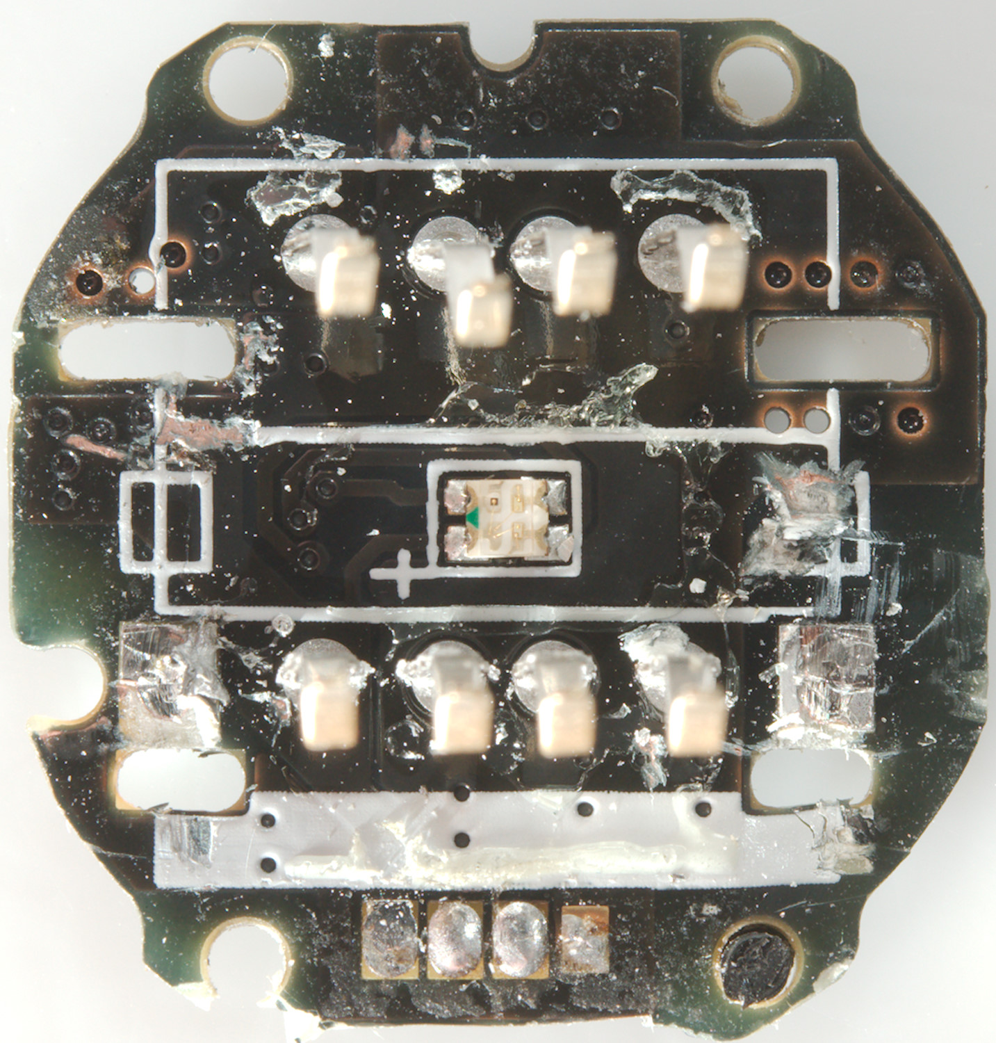
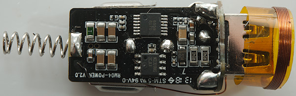
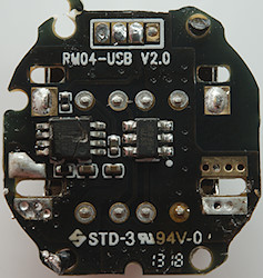
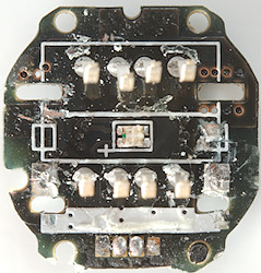
This circuit board is the switcher with a switcher controller, a power mos and two current sense resistors (R040: 40mOhm), one for each output. At the input is a fuse (Green part with a T) and about 80uF in five ceramic capacitors.
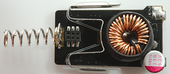
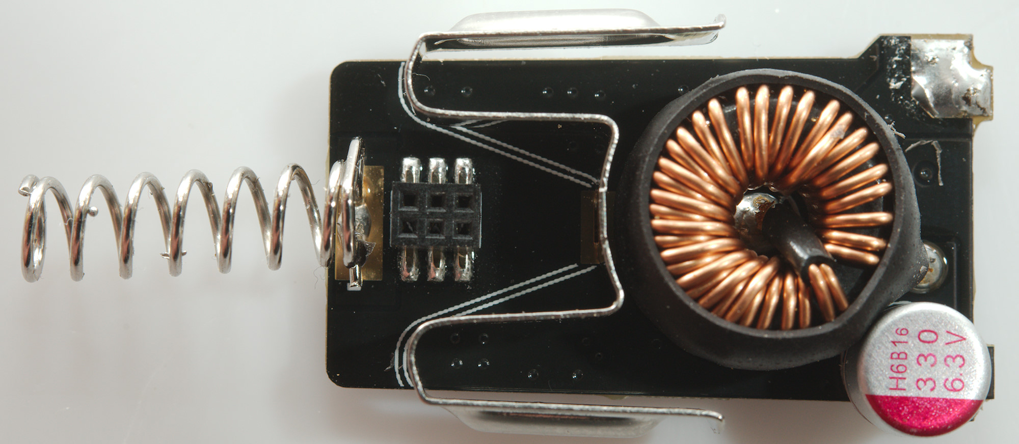
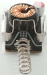
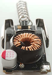
The other side is the inductor and a smoothing capacitor for the usb output voltage.
This board has 3 connections to the usb connectors: common 0V and a 5V for each output.

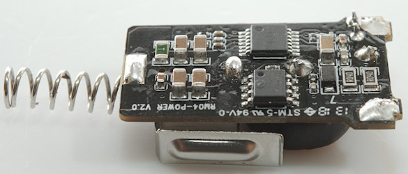
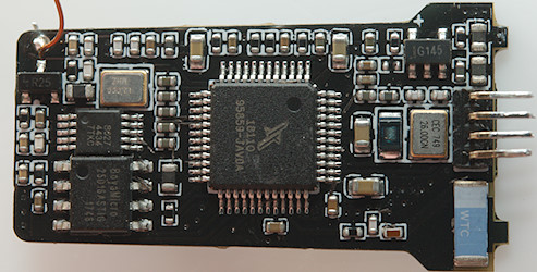
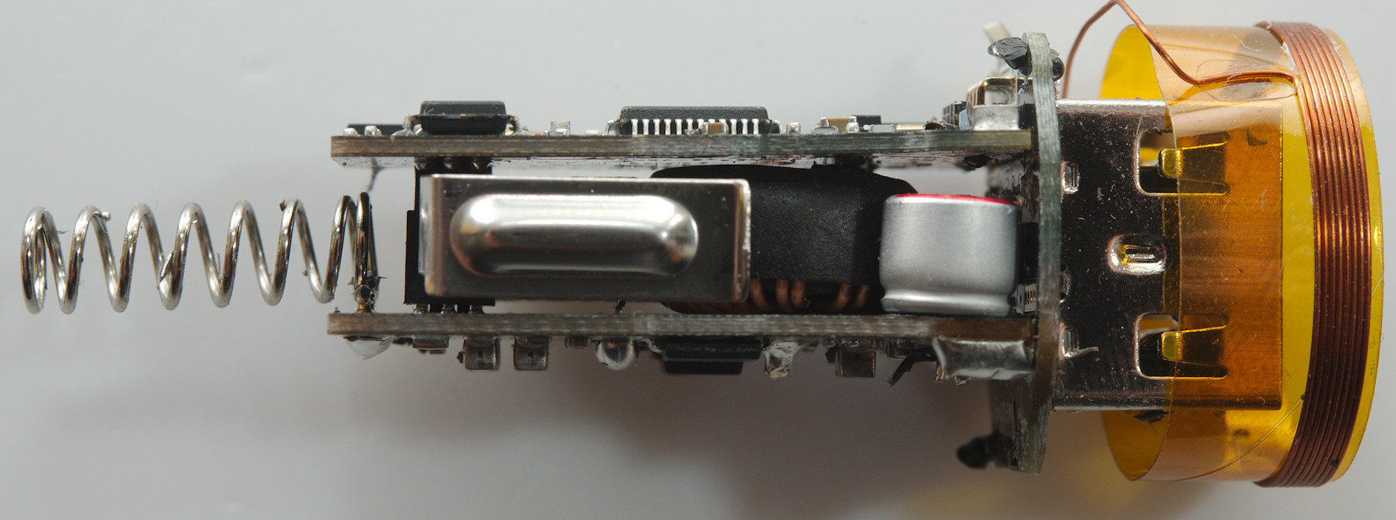
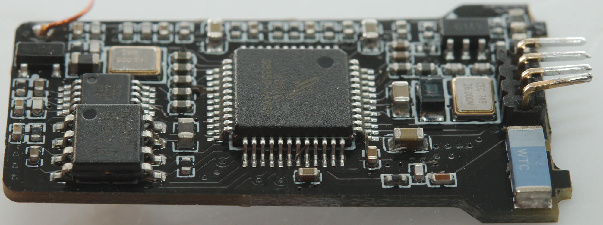
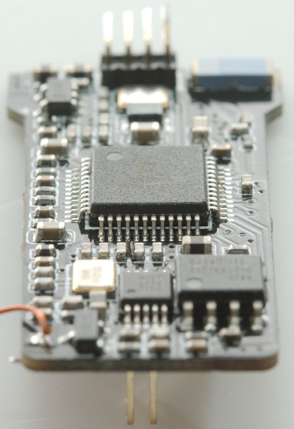
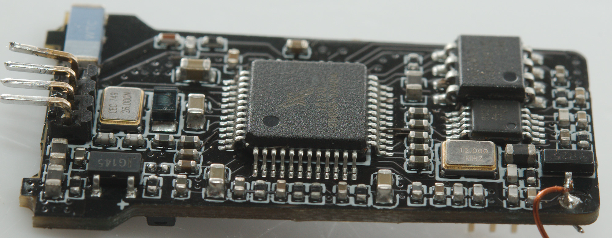
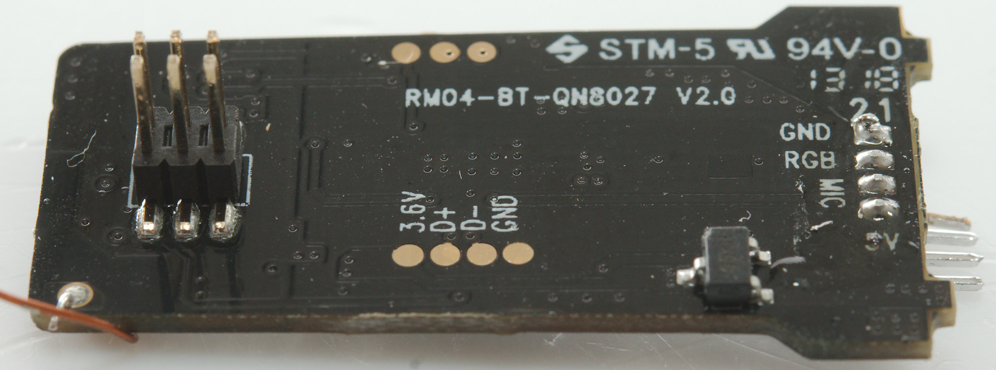
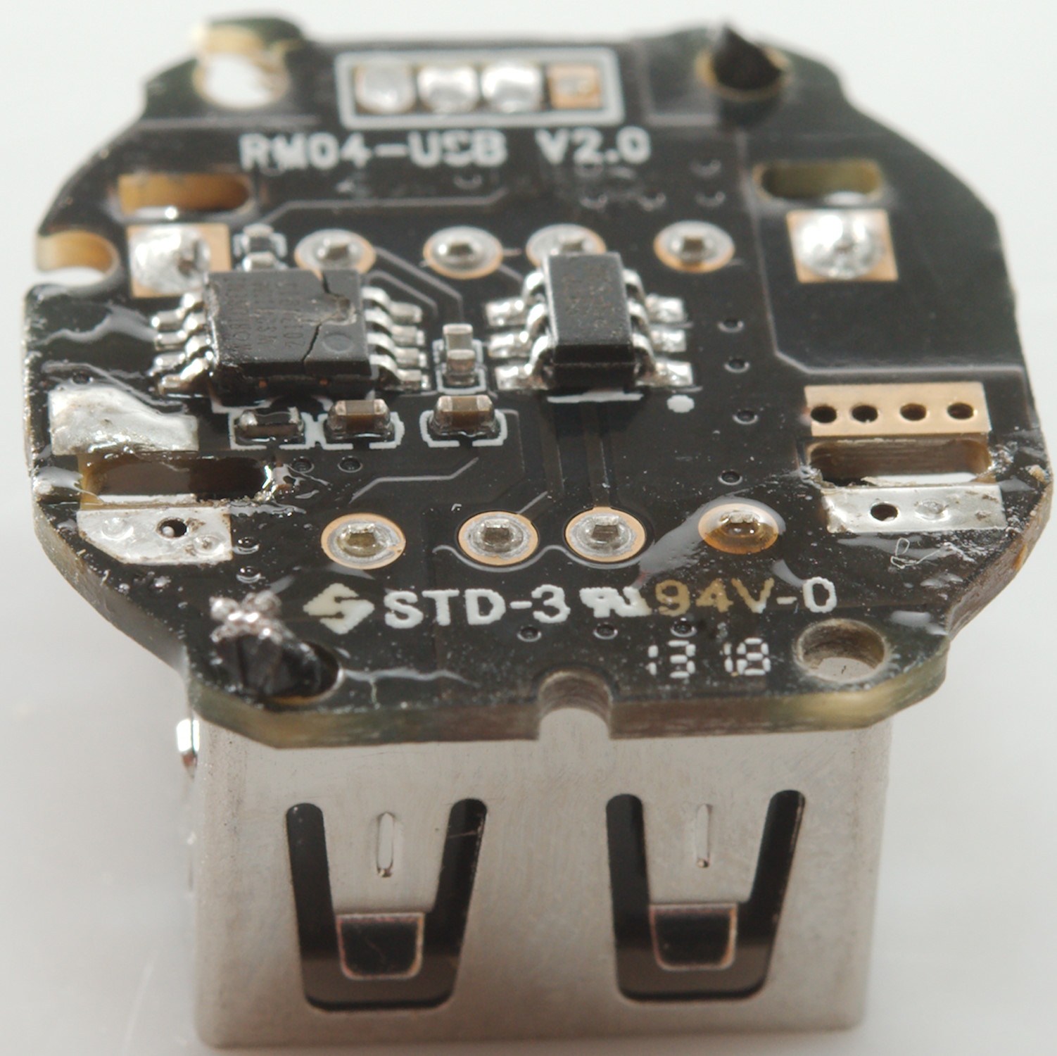
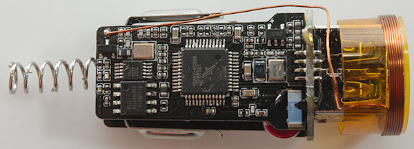
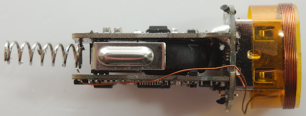
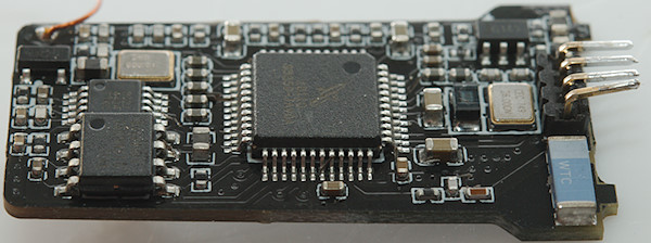
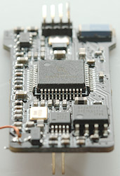
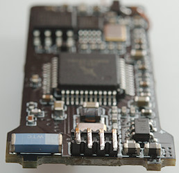
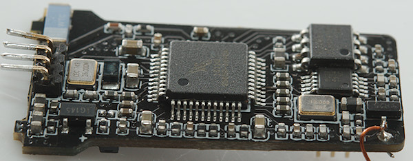
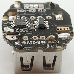
This circuit board has a FM transmitter (QN8027), some flash memory (BoyaMicro) and a processor with build in bluetooth, the bluetooth antenna is marked WTC.
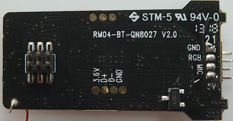
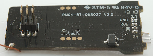
On this side is a 3.6V voltage regulator (Marked 65KH). The connector to the front is marked GND, RGB, MIC and 5V. The 3 of them is obvious, but what about MIC, is there a microphone in the front?

The damaged chip was from trying to pry the circuit board out, it is a 3 channel (i.e. RGB) serial controlled LED controller. The other chip must be a auto coding chip.
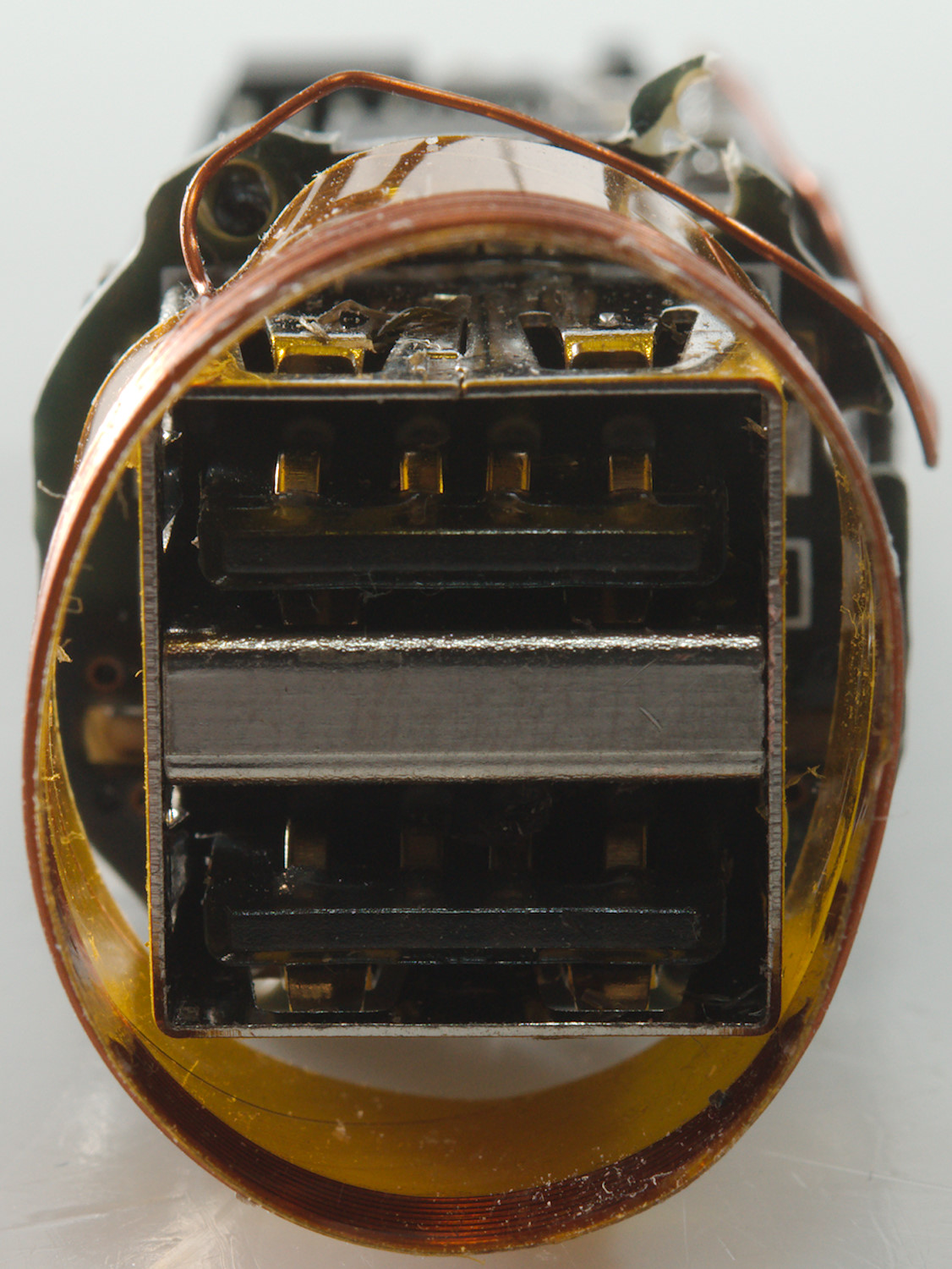
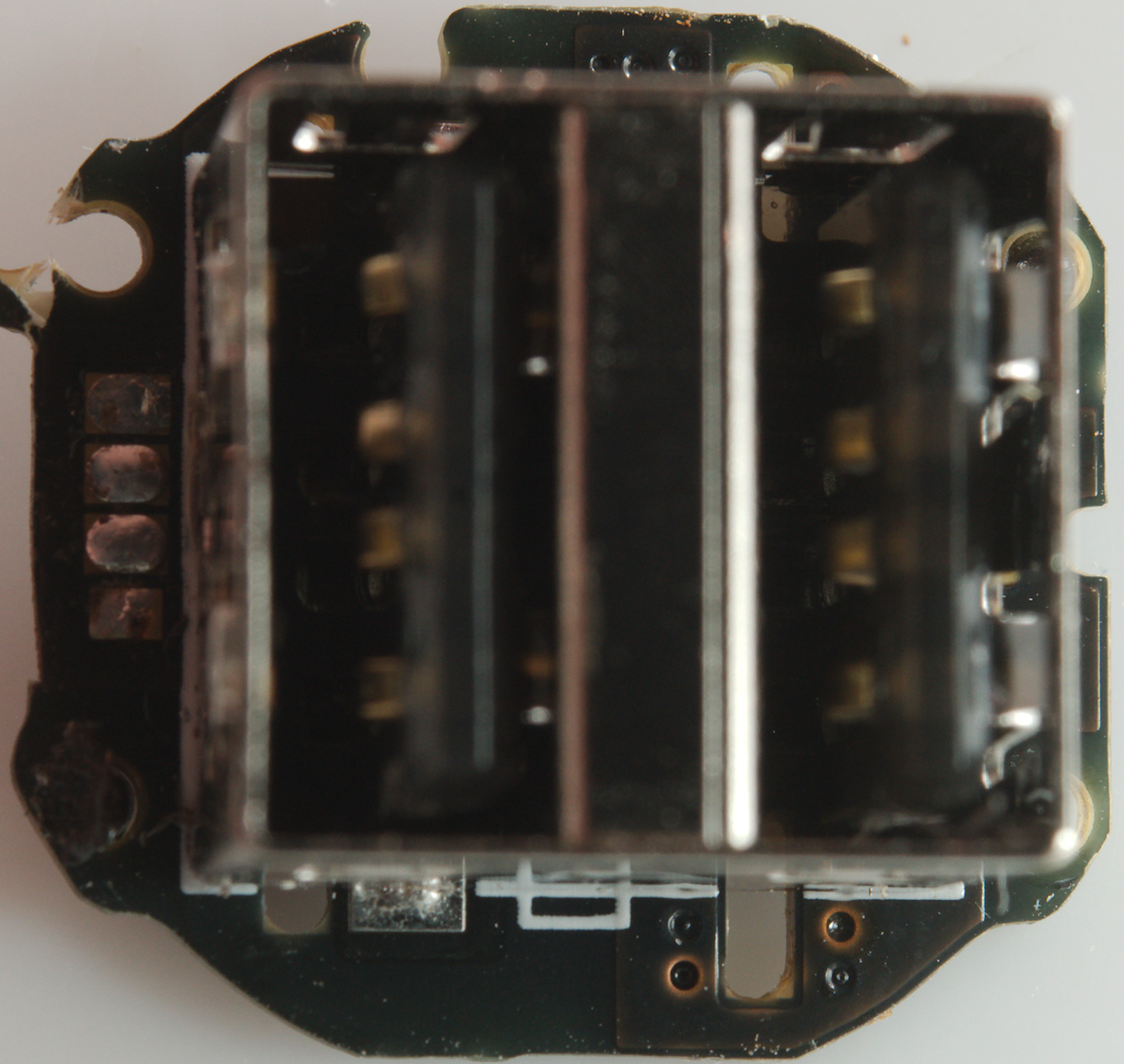
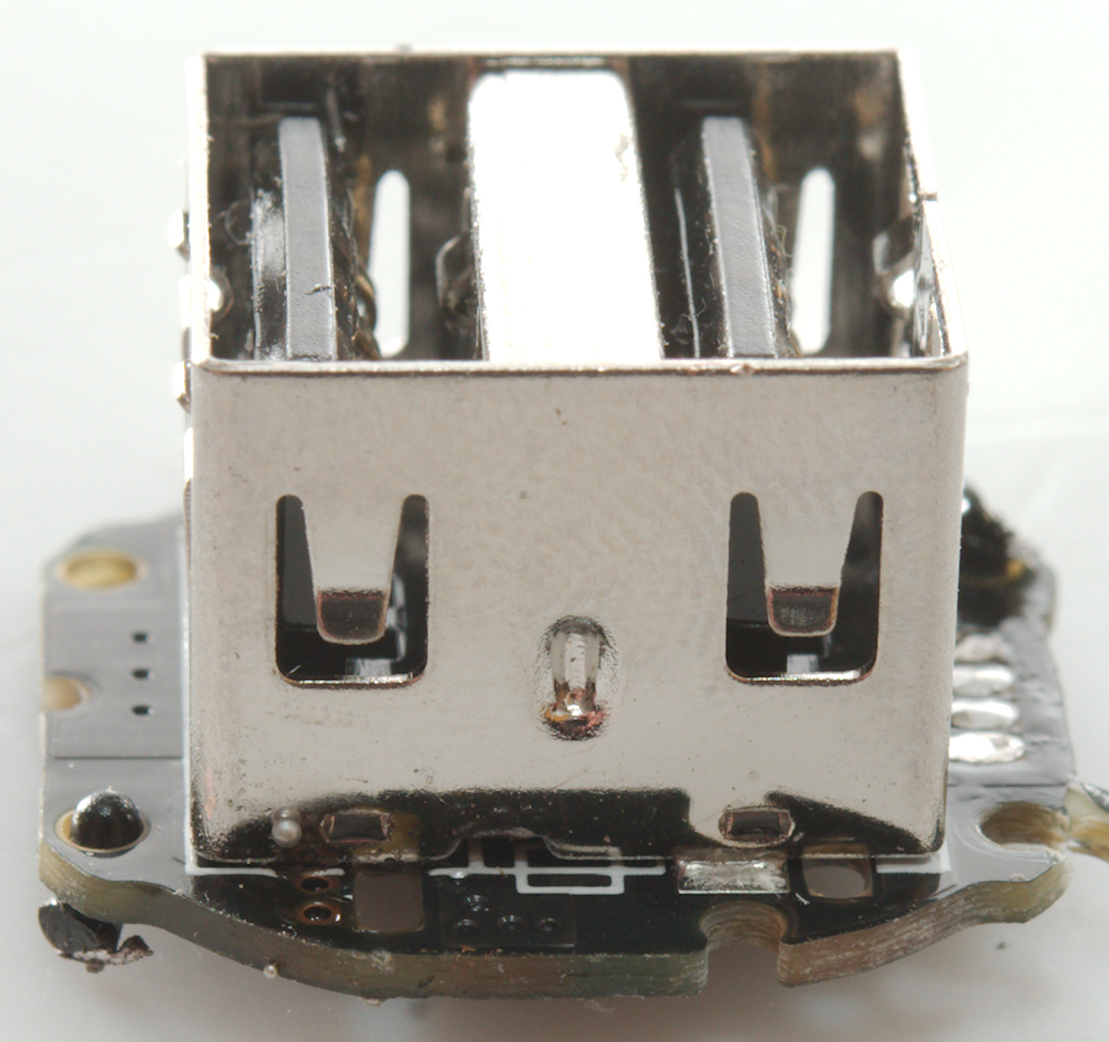
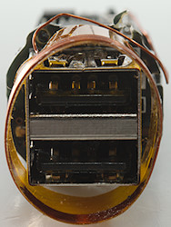
Here is the RGB led, below the usb connector. There is no microphone.
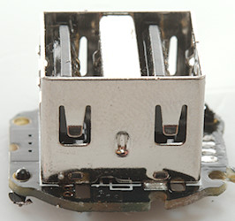
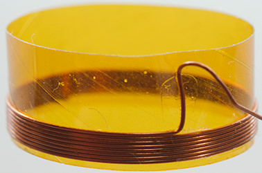
The FM antenna is a coil placed around the USB connector.
Being a 12V device there is no need to test with high voltages.
Conclusion
The charger has two output, each with a good overload protection, very low noise and auto coding. In addition to this it is also a FM transmitter that can link to a phone with Bluetooth and transmit music to the car radio (This is most useful in older cars).
This is a very good car charger, but it cannot fast charge two power hungry device simultaneous.
Notes
There also exist a version with microphone, this is used for a hand-free function with the phone.
Index of all tested USB power supplies/chargers with DC input
Read more about how I test USB power supplies/charger