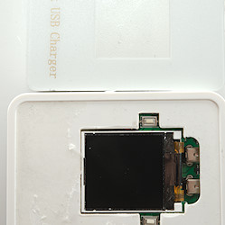
Smart USB charger with DC input
Official specifications:
- Input voltage: DC 12-36V
- Input interface: DC5.5*2.1 (Some notebook adapters can be directly inserted)
- Output voltage and current: channel 1-3 QC2.0, fixed output 5V/1A-2.4A; channel 4 QC3.0, automatic output 5V/3.4A, 9V2.3A, 12V/1.5A
- Maximum current: 8.5A
- Maximum power: 45W
- Product Size: 77.5*54*28MM
- Product weight: 92.5g
I got it from Aliexpress dealer Good Idea store
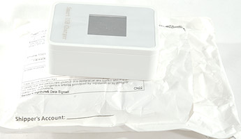
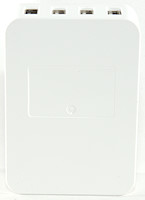
No fancy box for this charger, only a envelope.
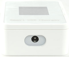
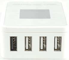
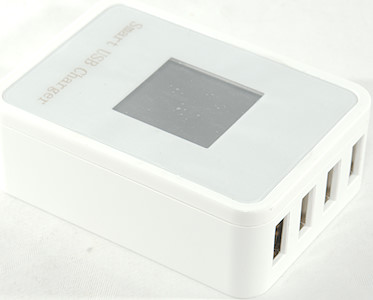
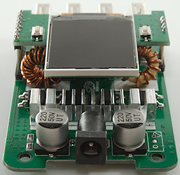
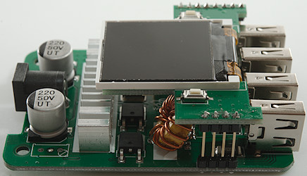
Power input is a DC connector and it has four usb outputs.
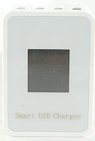
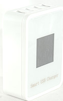
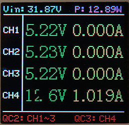
The display is nice with input voltage and power and output voltage and current for each output. As can be seen my display had a few dead pixels.
The listing on the bottom with "QC2: CH1~3" is wrong, they are regular usb output not Quick Charge 2.0.
Measurements
- Standard usb outputs supports Apple 2.4A, Samsung and DCP
- QC output supports Appe 2.4A, DCp, QC3, Samsung-AFC, Huawei-FCP
- Minimum QC3 voltage is 3.8V
- Current consumption when idle is 102mA
- Weight: 92.2g
- Size: 82 x 58.5 x 27.7mm
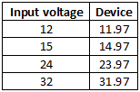
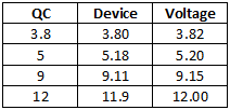
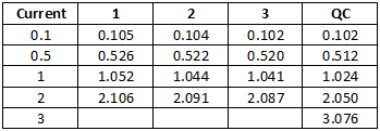
The voltage and current displays are fairly good, but not high precision (Device is displayed values, voltage/current columns is measured values).
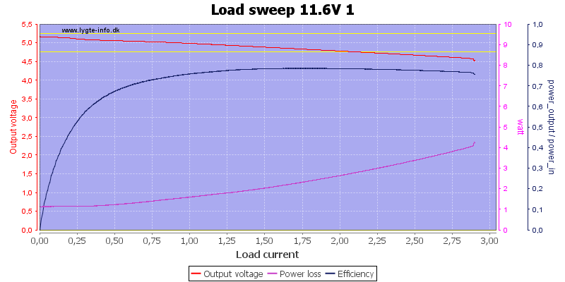
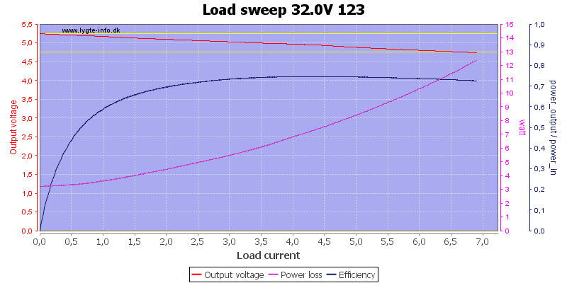
All 3 regular usb outputs has overload protection around 2.8A, but it looks like the resistor for measuring output current adds a voltage drop to the output.
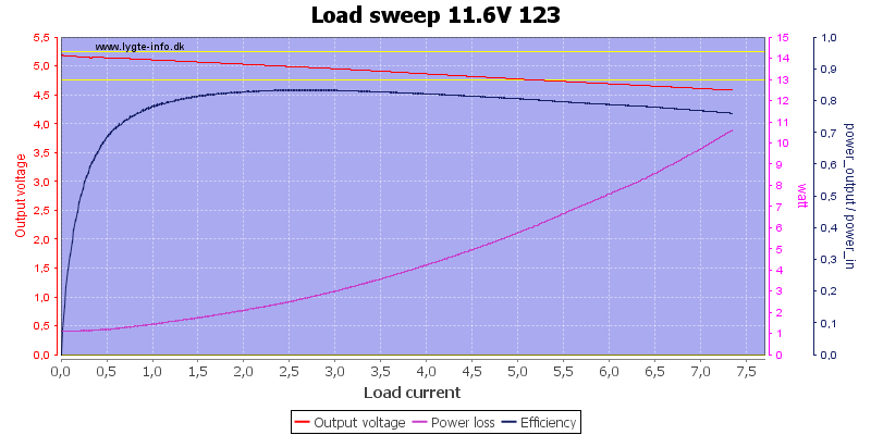
Running all 3 in parallel means a total current of around 7.2A, but it do heat the box significantly.
At higher voltage the maximum current drops slightly and the heat increase a few watts.
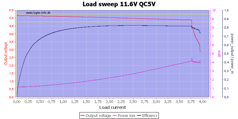
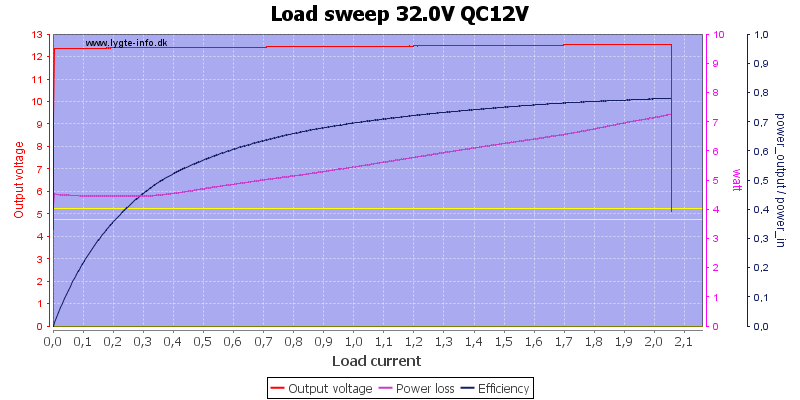
The QC output can deliver about 3.7A and output voltage do not drop as much when loaded (Voltage sense is probably placed after current sense resistor).
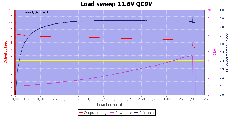
At 9V the current is 3.5A, it looks like the input voltage is a bit too low for full 9V during load.
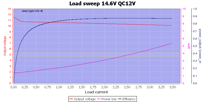
12V cannot maintain full output with 14.6V input, but it can deliver 3.5A
Increasing input voltage makes the 12V stable at any load, but here it is limited to about 2A and the power loss in the box is rather high.
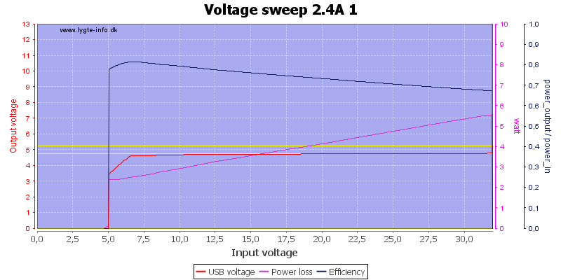
The power loss is very depend on the input voltage.
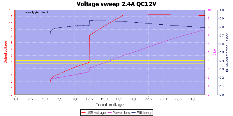
The QC12V needs about 18V input before it can deliver 2.4A output (That was not a completely fair test, it is only rated for 1.5A).
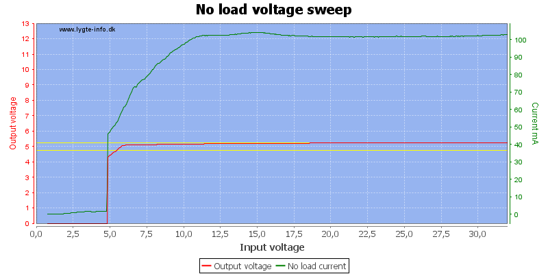
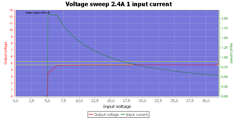
The idle current is rather high on the charger and it independent of the input voltage, this is not good for efficiency at higher input voltages.
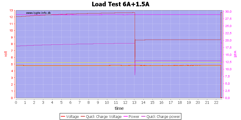
For first test I used 6A on 5V usb connectors and 1.5A at 12V on QC. The QC output broke down after 13 minutes, the other outputs after 22 minutes, not very impressive.
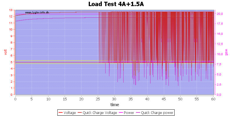
At 4A the regular usb output is stable, but the 12V QC has problems with 1.5A
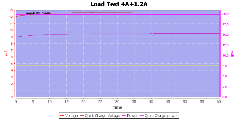
With 4A on regular usb outputs and 1.2A on QC 12V everything worked for one hour.
The temperature photos below are taken between 30 minutes and 60 minutes into the one hour test.
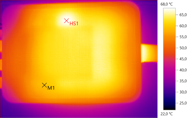
M1: 58.7°C, HS1: 68.0°C
The charger is warm.
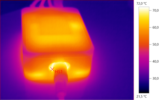
HS1: 72.0°C
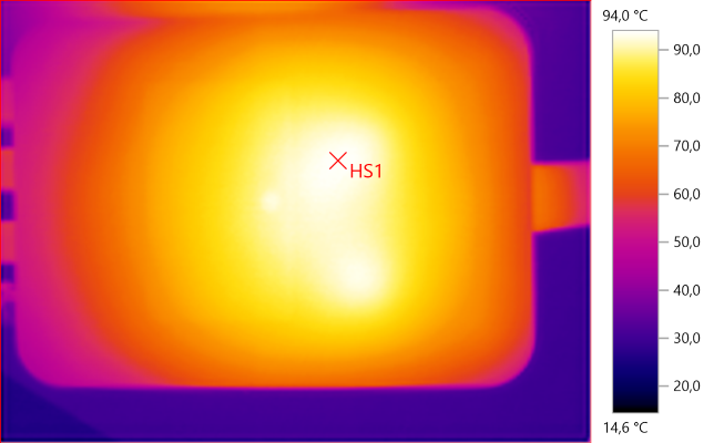
HS1: 94.0°C
The back of the charger gets rather hot at this power level.
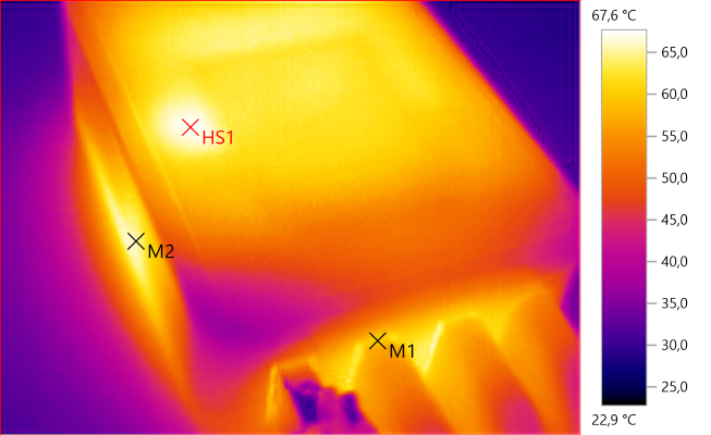
M1: 59.8°C, M2: 65.5°C, HS1: 67.6°C
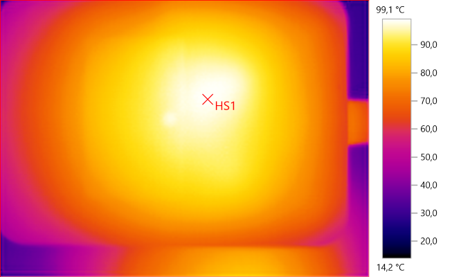
HS1: 99.1°C
Here is a photo from a 5A+1.5A test, the back of the charger got slightly warmer, between shutdowns.
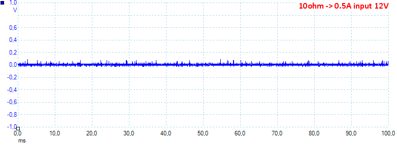
Noise at 0.5A output is 19mV rms and 134mVpp
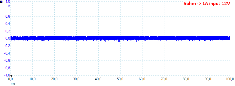
Noise at 1A output is 36mV rms and 292mVpp
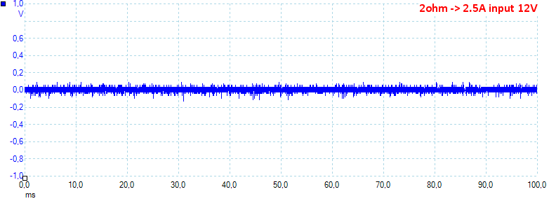
Noise at 2.5A output is 125mV rms and 395mVpp
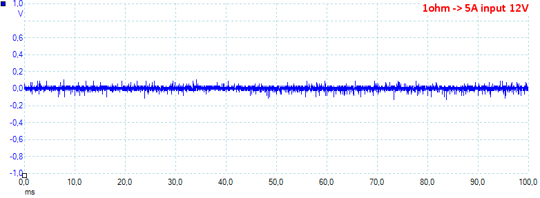
Noise at 5A output is 34mV rms and 349mVpp
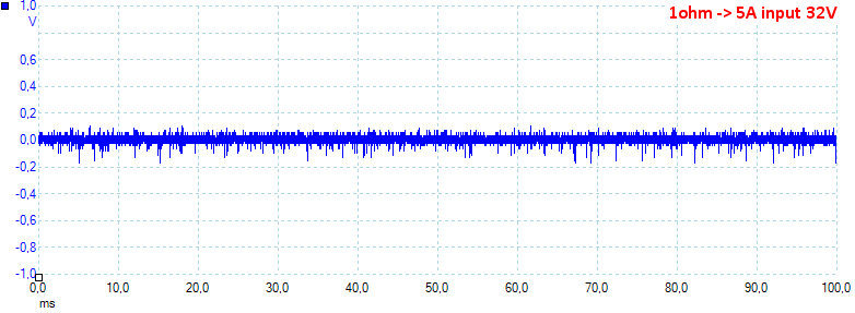
Noise at 5A output is 39mV rms and 335mVpp
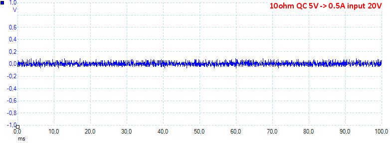
Noise at 0.5A on the QC output is 37mV rms and 600mVpp
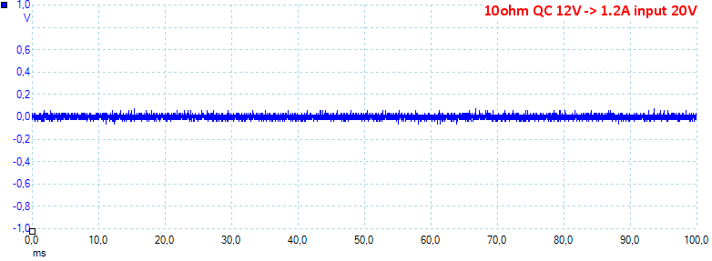
Noise at 1.2A on the QC output is 26mV rms and 197mVpp, all low noise values.
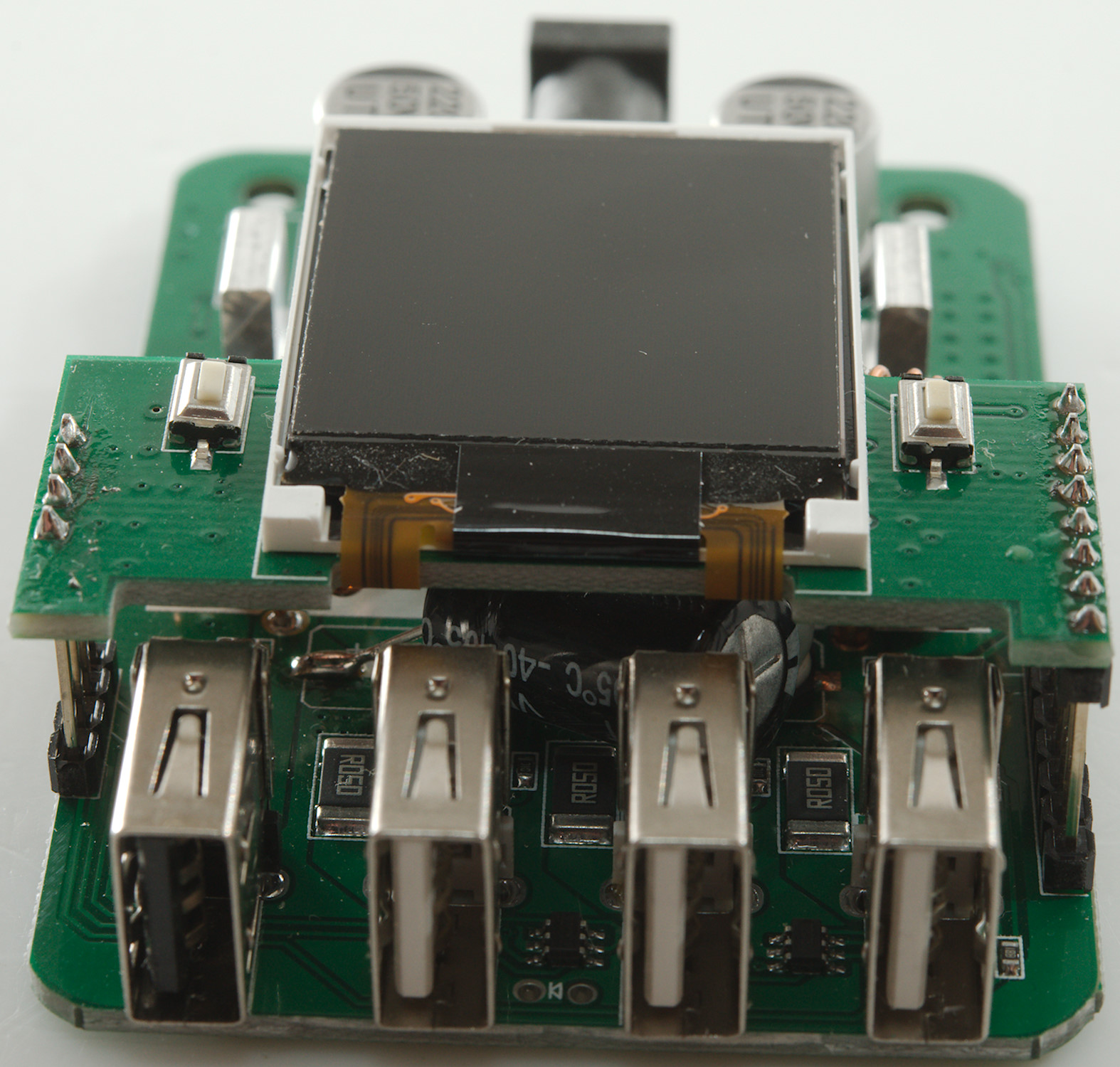
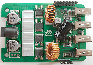
Tear down
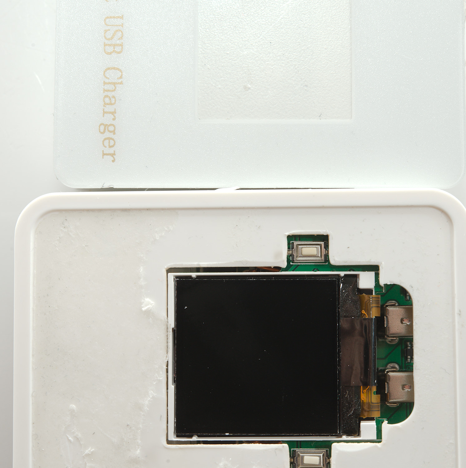
There was no visible screws and a check below the front foil did not help, but it revealed two buttons.
I tested a bit, but did not find any obvious functions for them, but that may be because I missed the 3. switch.

I had to break it open, the lid was glued (or ultrasonic welded) on.
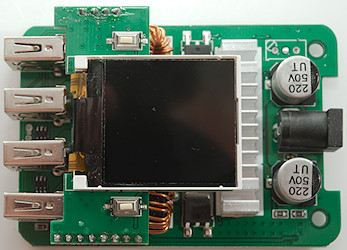
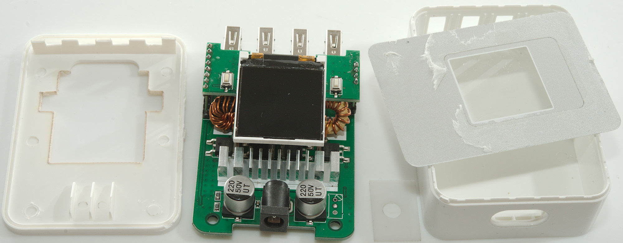
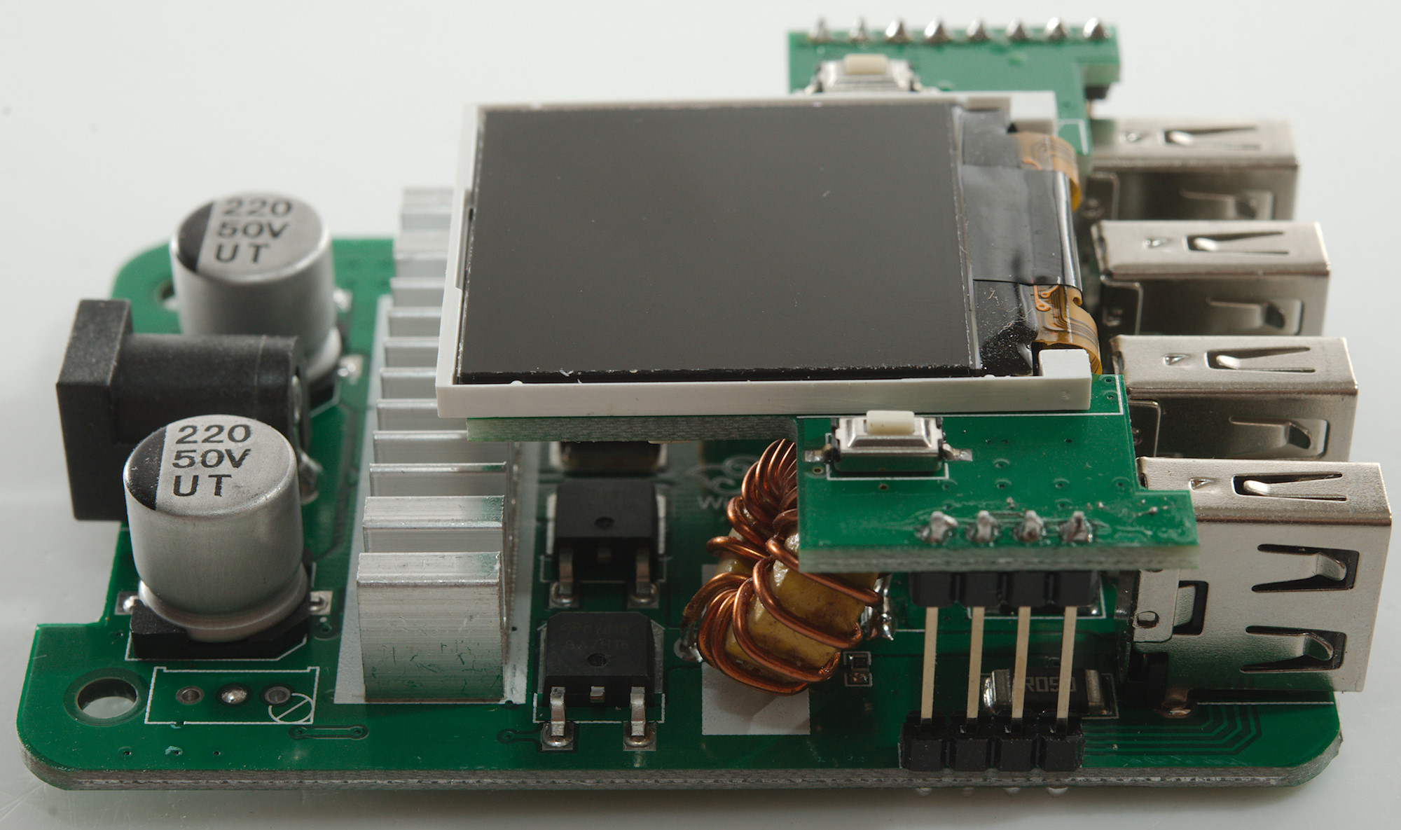
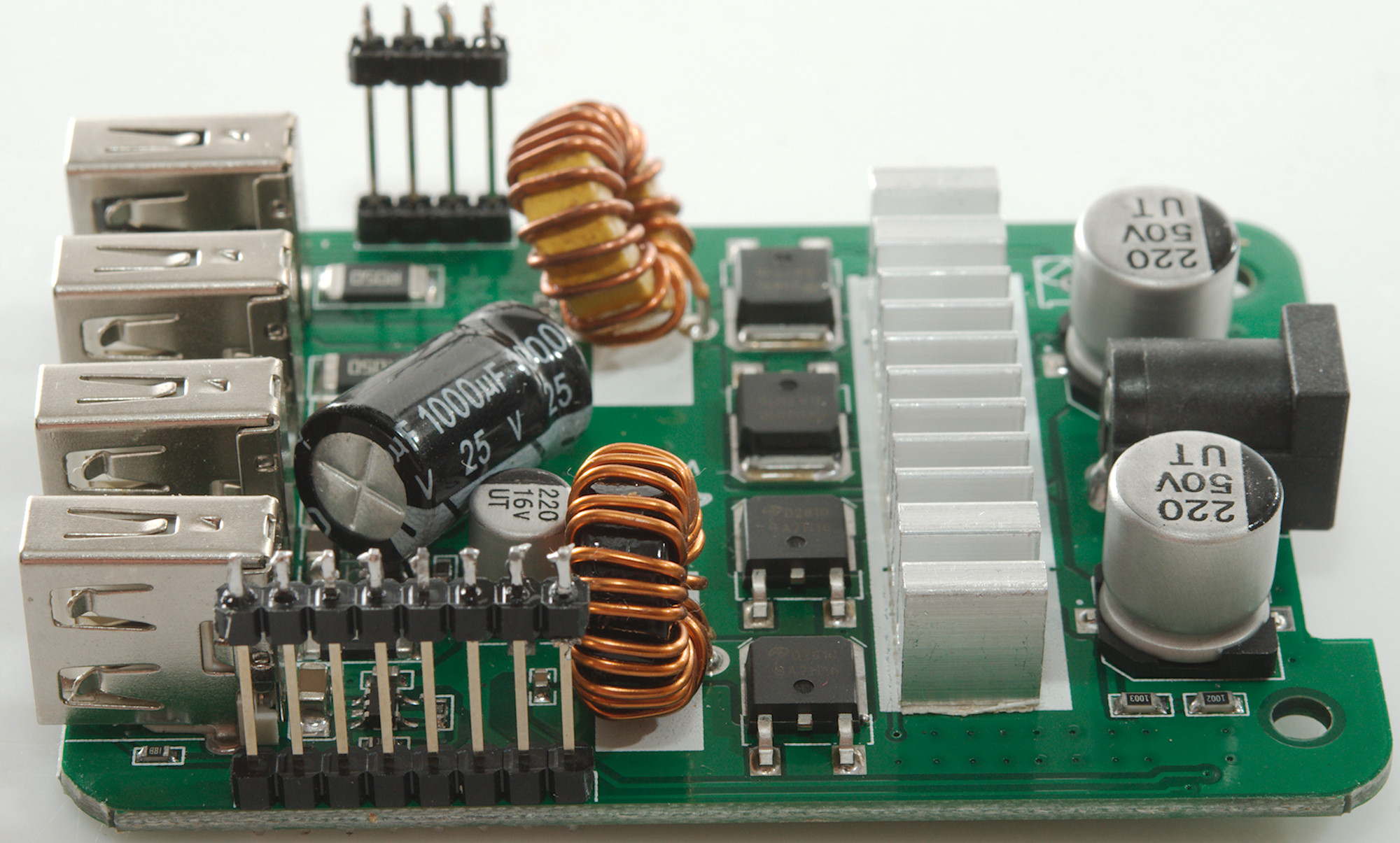
It is a two layer construction with the display on the upper layer.
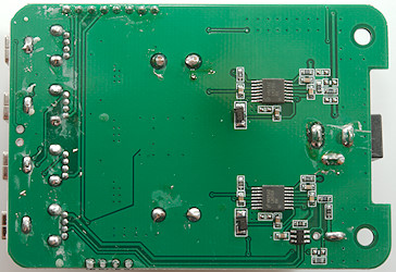
On the bottom is the two switchers (2xLM3150), one for the normal usb and one for QC with the controller (FT4) next to it.
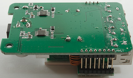
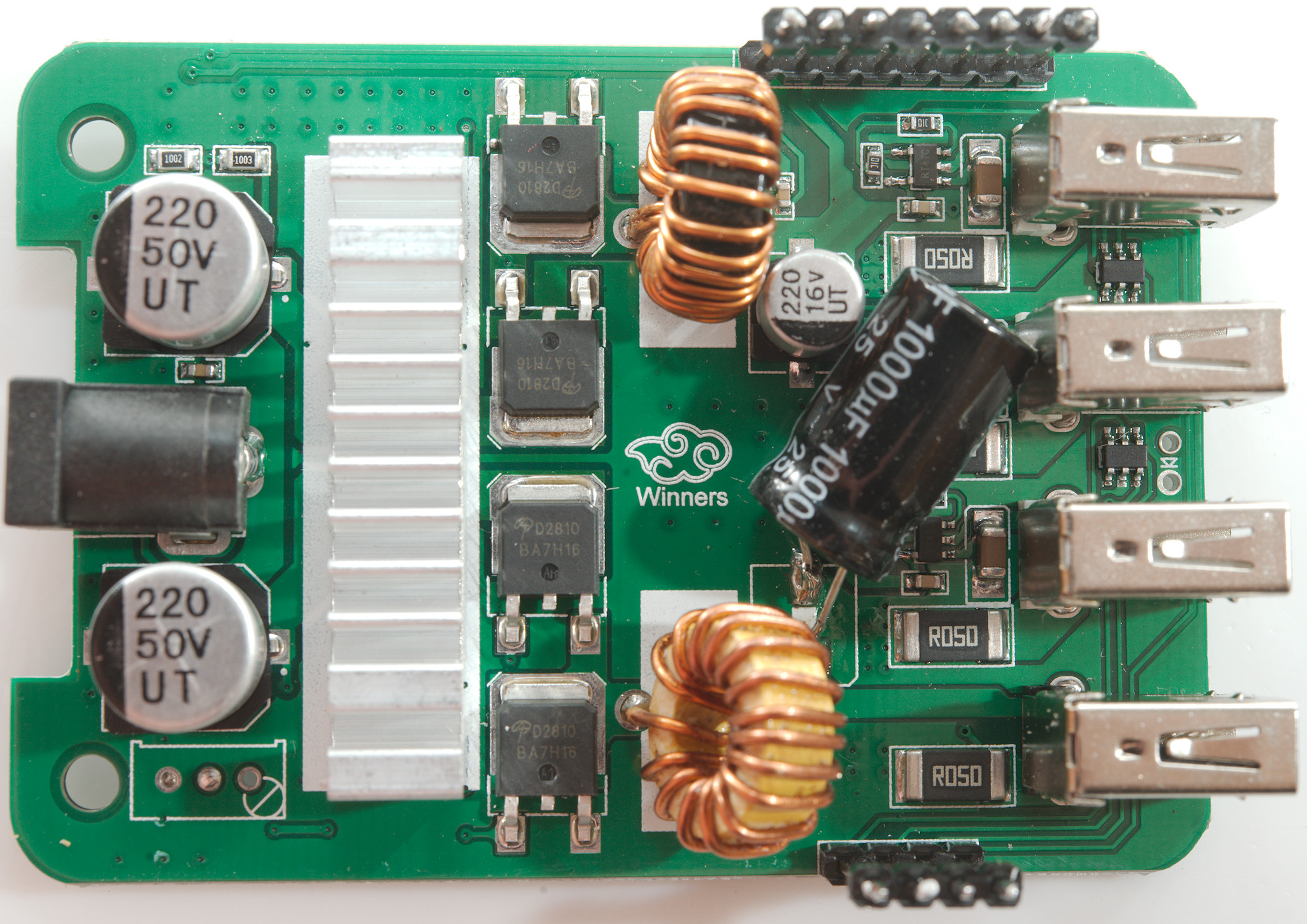
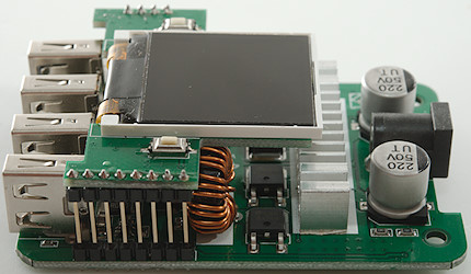
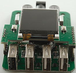
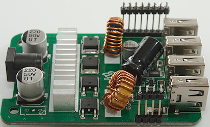
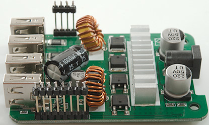
Some soldering and I could split the two circuit boards apart.
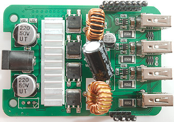
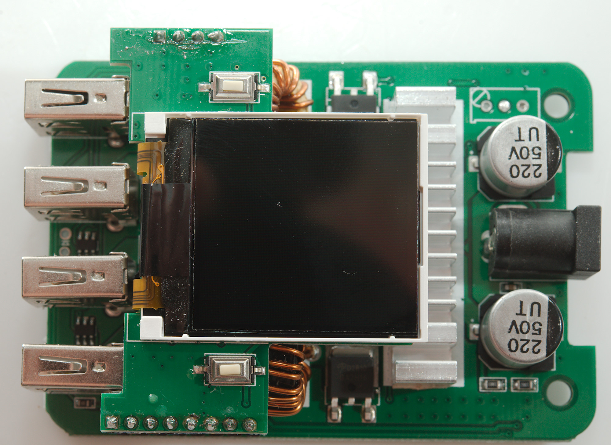
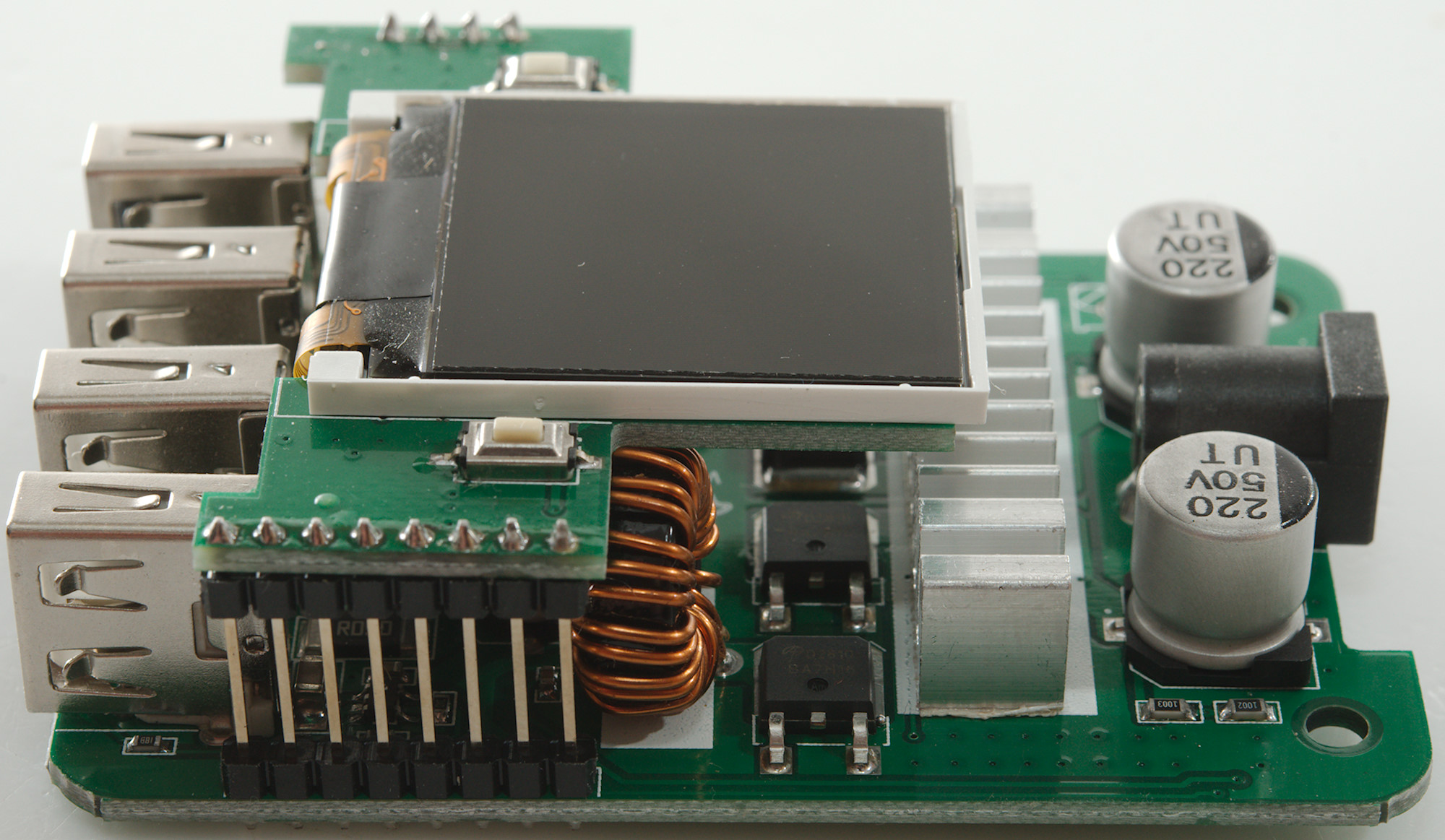
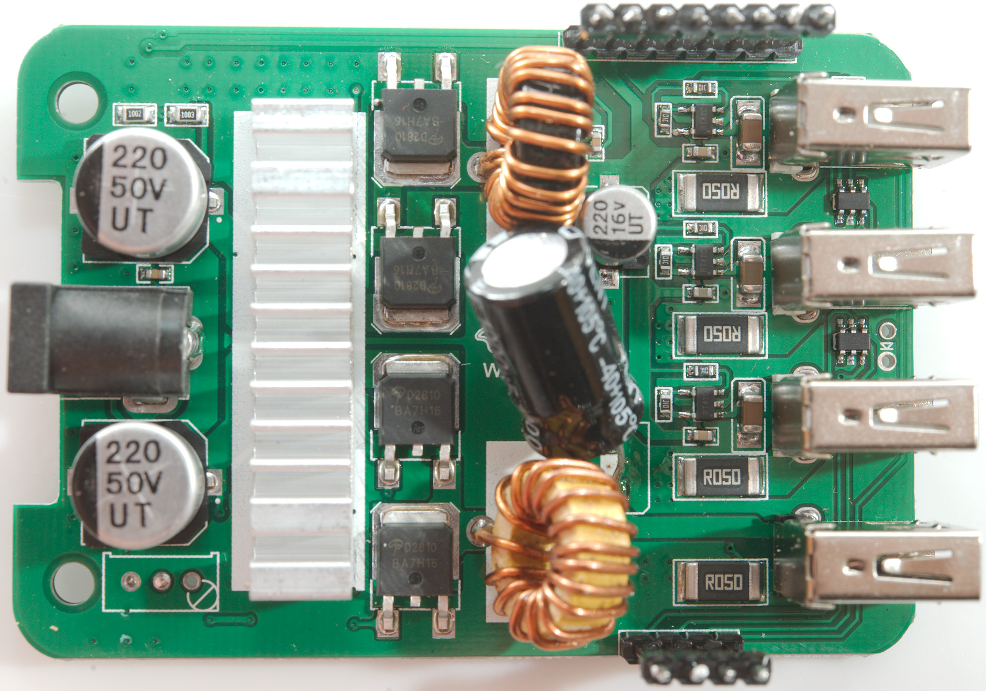
Next to the heatsink are 4 power mos (AOD2810) they are used by the two switcher controllers on the other side of the circuit board, two for each switcher. This means it is a synchronous circuit with fairly low power loss.
Behind the usb connectors is the current sense resistor (R050: 50mOhm) and the current limiting IC (RT4TC). Between the usb connectors is the auto coding IC (RZC7512).
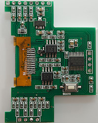
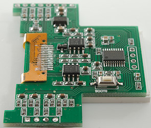
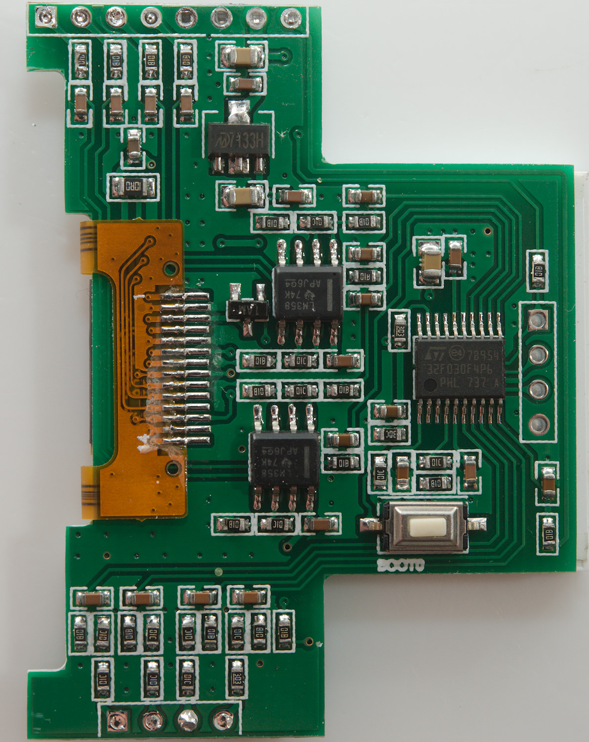
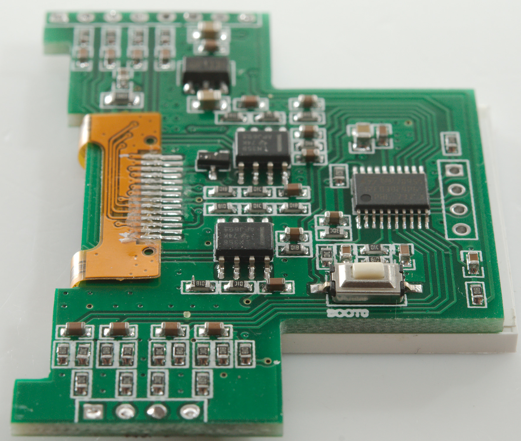
The display board uses a microprocessor (STM 32F030F4P6: 16kB flash). It has two dual OpAmps (LM358), probably to amplify the signal from the current shunts and a voltage regulator (7133H: 3.3V). There is also a "hidden" button.
It looks like the 4 pin connection is voltage input and the 8 pin is current, gnd and power input. All the voltage/current inputs has a RC filter.
Conclusion
I like the display with voltage and current and it would work with an old laptop power supply, but the efficiency is too low and the heatsink is too small, at least if it is used for fast charging a couple of devices.
I will only rate it as fairly good, due to the heat problems.
Notes
Read more about how I test USB power supplies/charger
Compare car chargers and other DC supplied chargers