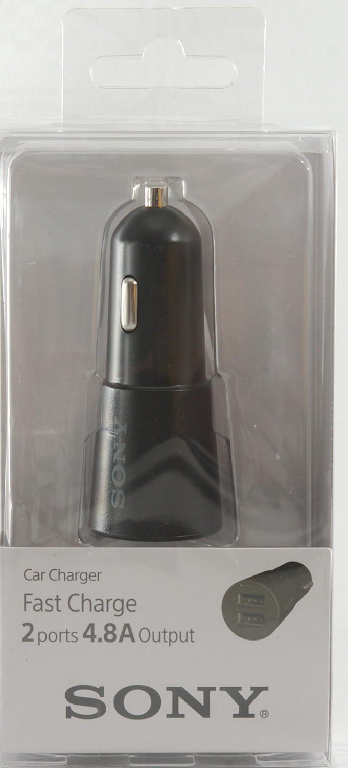
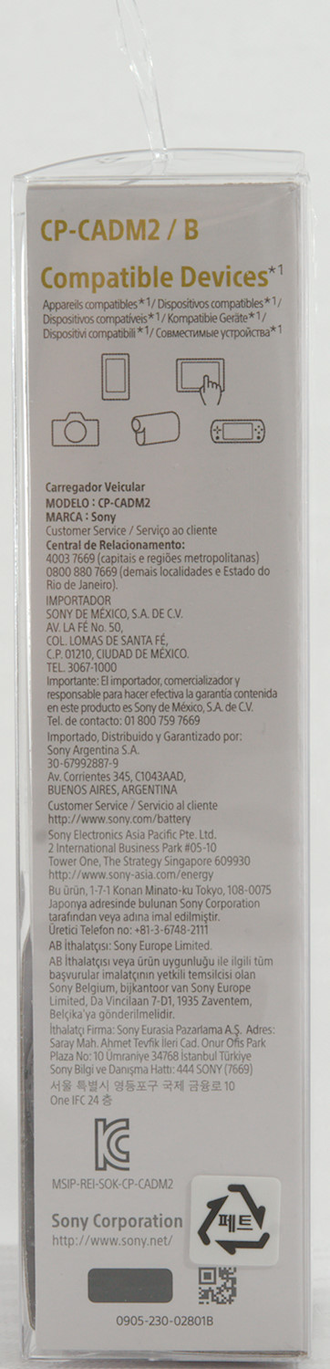
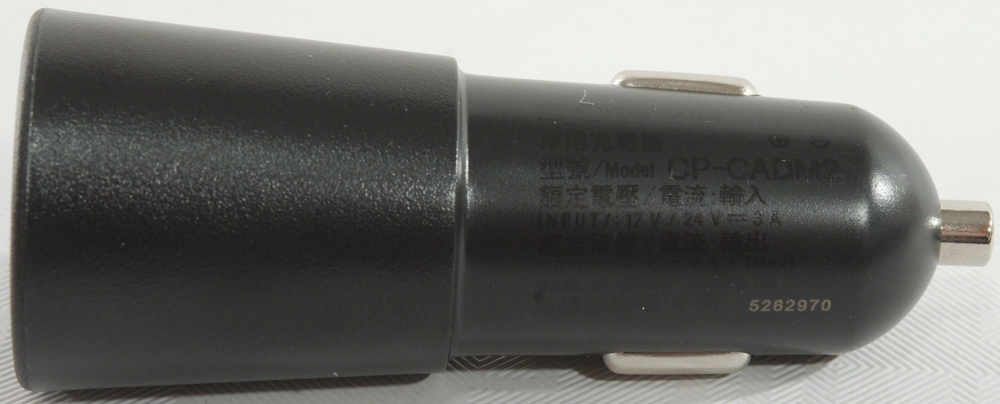
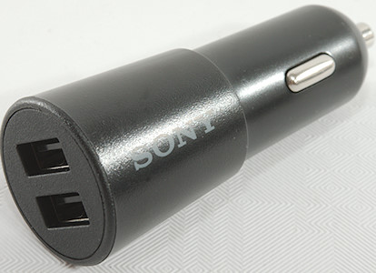
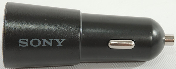
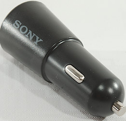
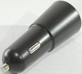
Sony Fast Charge Car Charger 4.8A CP-CADM2 B
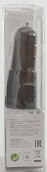
Official specifications:
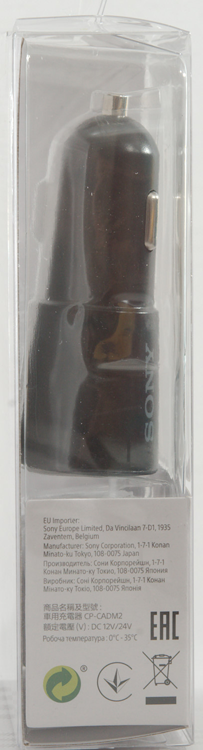
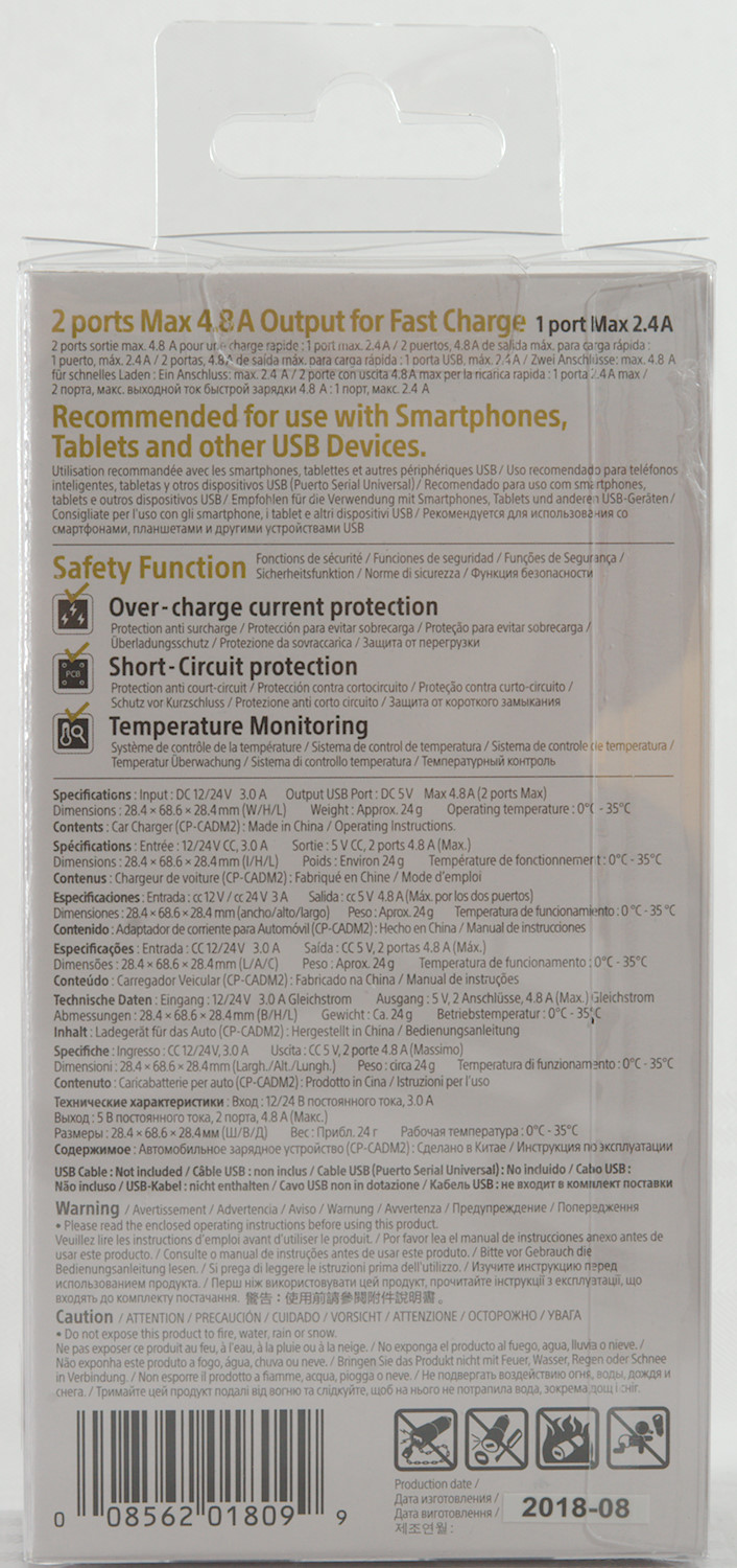
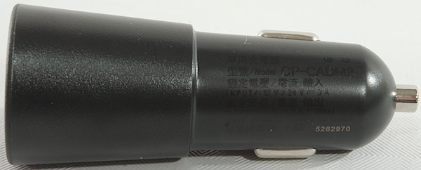
- Input: DC 12/24V 3.0A
- Output: 5V 4.8A (2.4A on each output)
- USB outputs: 2
- Weight: 24g
- Size: 28.4 x 68.6 x 28.4mm
I got it from amazon.de
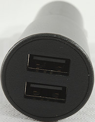
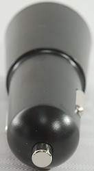
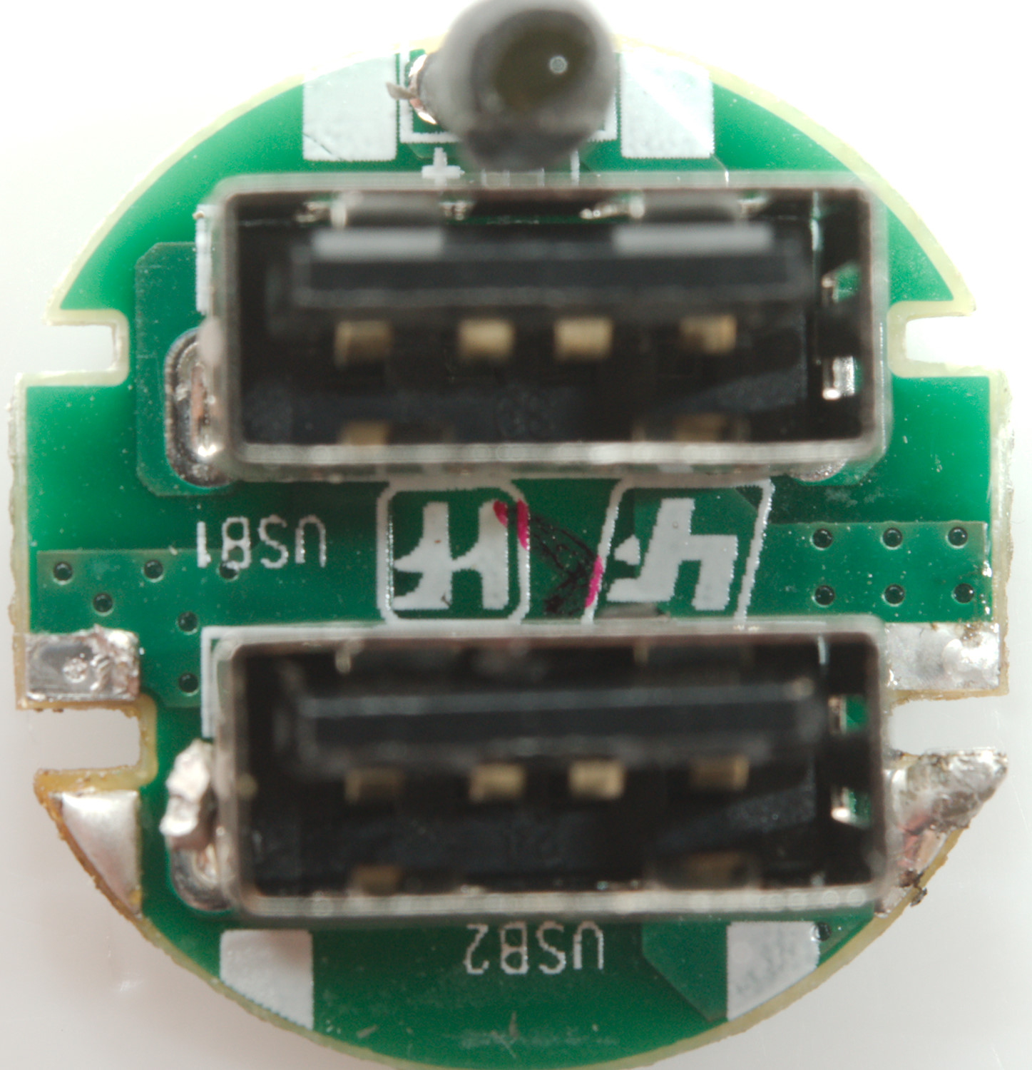
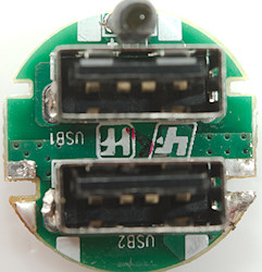
There is a small round led behind the black plastic above the USB connectors.
Measurements
- Power consumption when idle is 10.4mA from 12V and 9.3mA from 24V
- Both USB outputs is coded as Apple 2.4A
- It has a white led on the front.
- The +5V is in parallel and there is separate current sense is in the GND lines.
- Weight: 24.3g
- Length: 71mm
- Diameter: 28.5mm
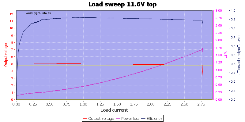
The USB output can deliver 2.7A, this is fine for a 2.4A rated charger.
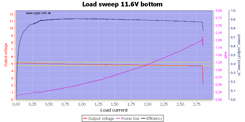
The other output is nearly the same.

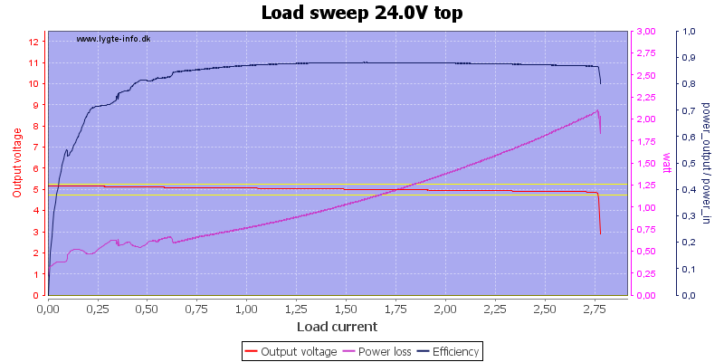
Different input voltage do not change the output current.
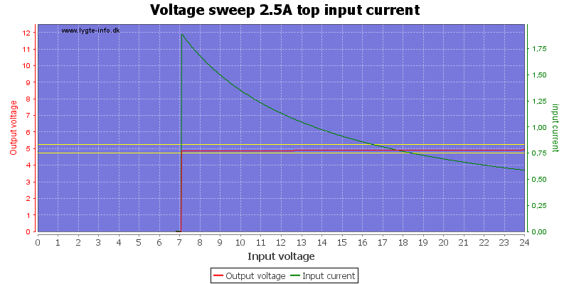
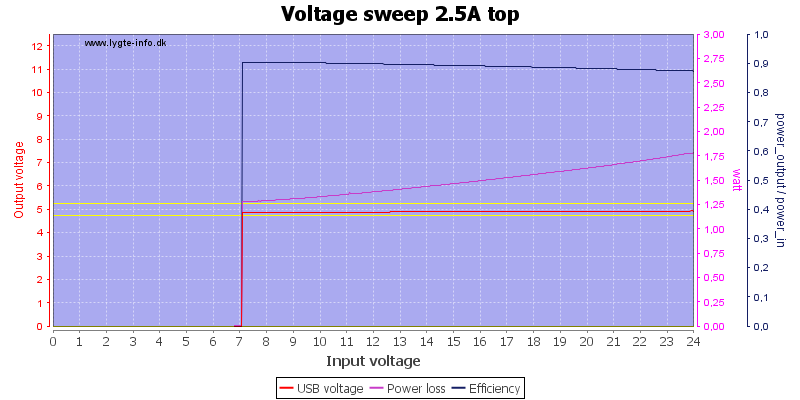
The charger works down to 7V when drawing 2.5A
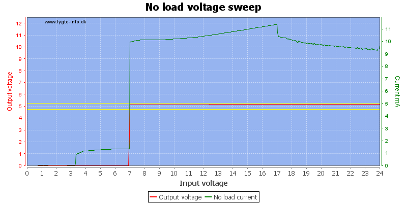
The unloaded current draw is fairly independent on voltage.
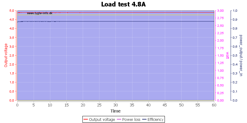
I did this test at rated 4.8A current and the charger could handle that.
The temperature photos below are taken between 30 minutes and 60 minutes into the one hour test.
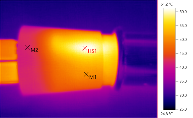
M1: 50.3°C, M2: 42.1°C, HS1: 61.2°C
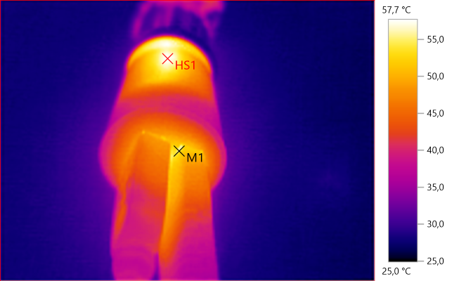
M1: 55.2°C, HS1: 57.7°C
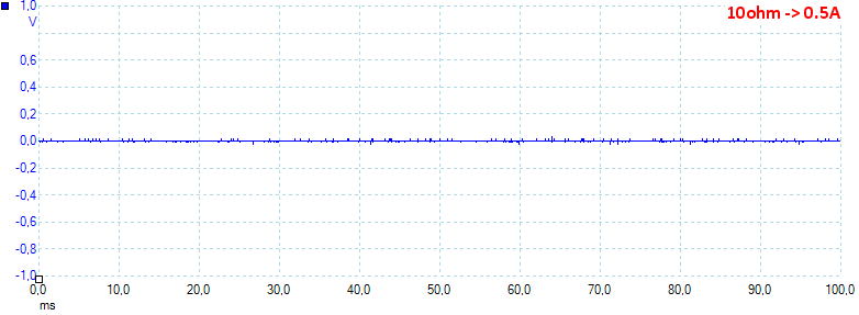
Noise at 0.5A output is 6mV rms and 79mVpp
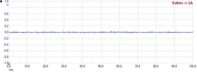
Noise at 1.0A output is 7mV rms and 88mVpp
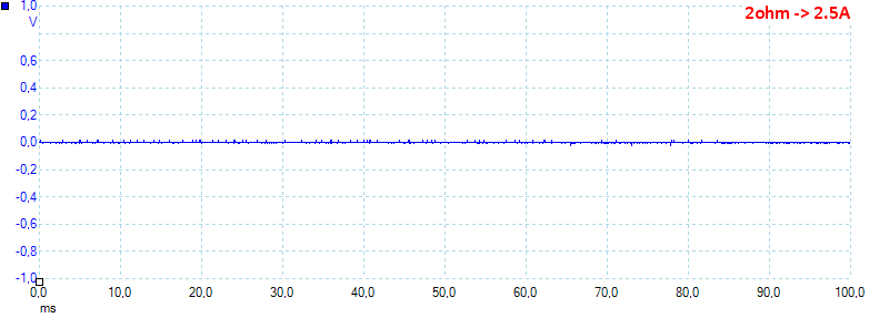
Noise at 2.5A output is 6mV rms and 70mVpp, this is very low noise.
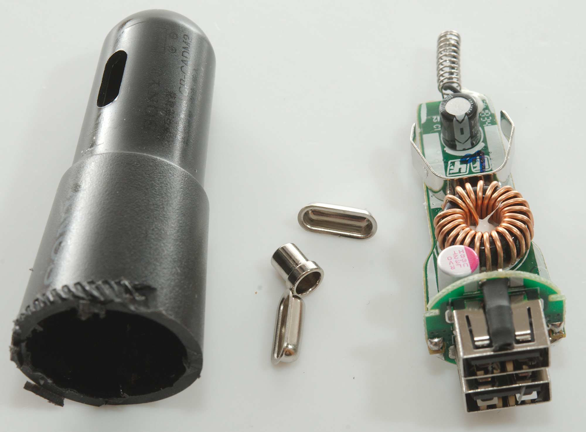
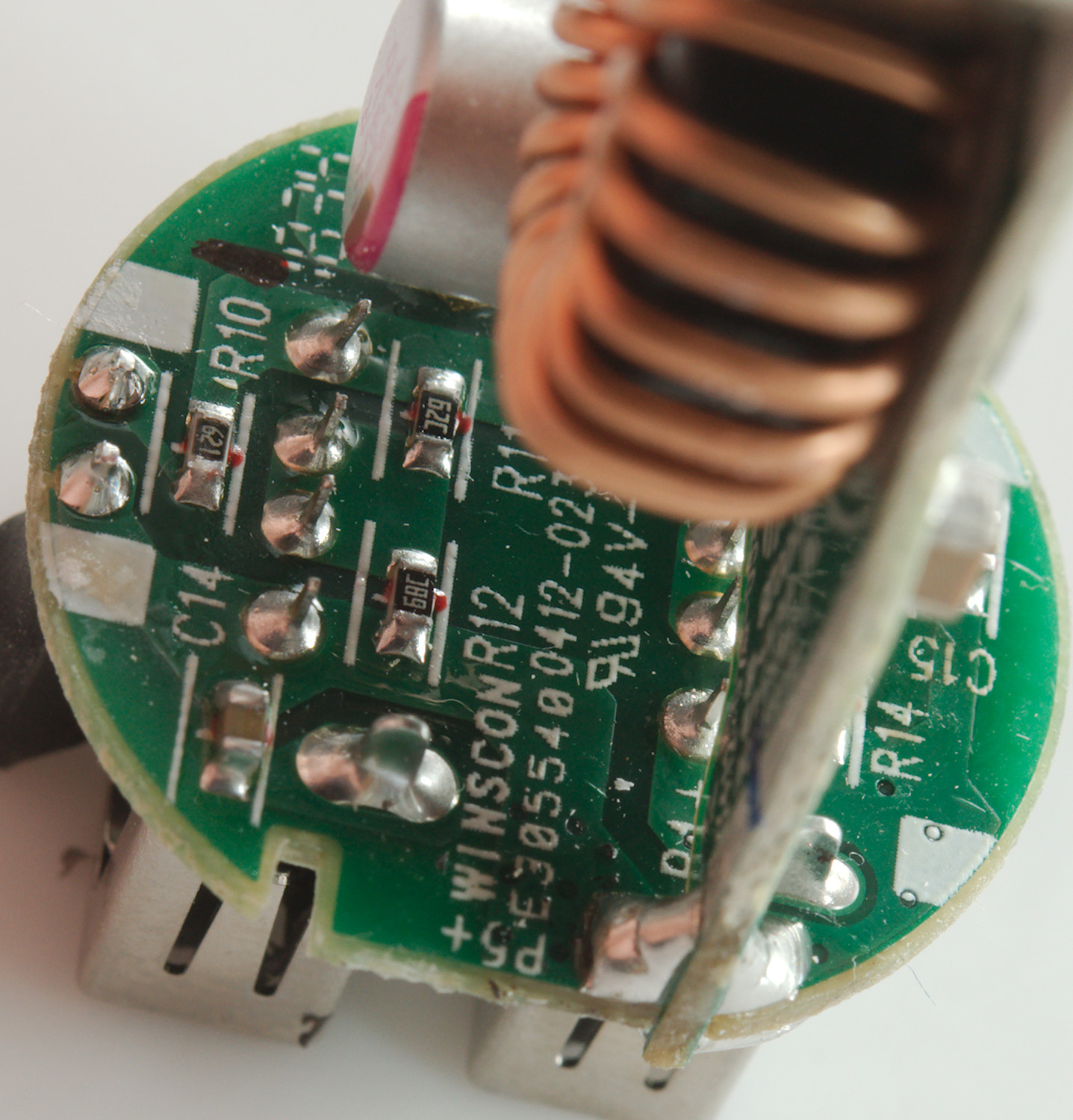
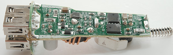
Tear down

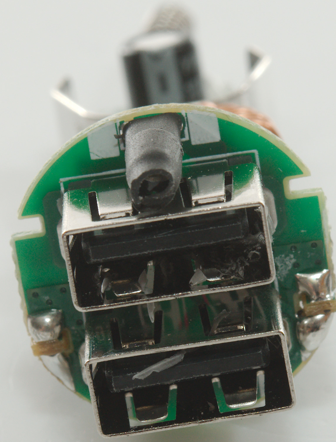
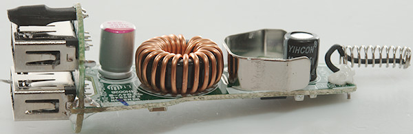
I could not get the front of the charger and decided to cut it away.
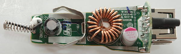
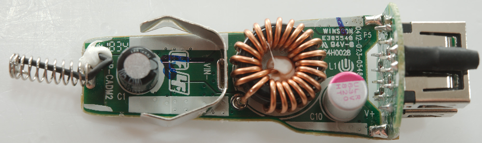
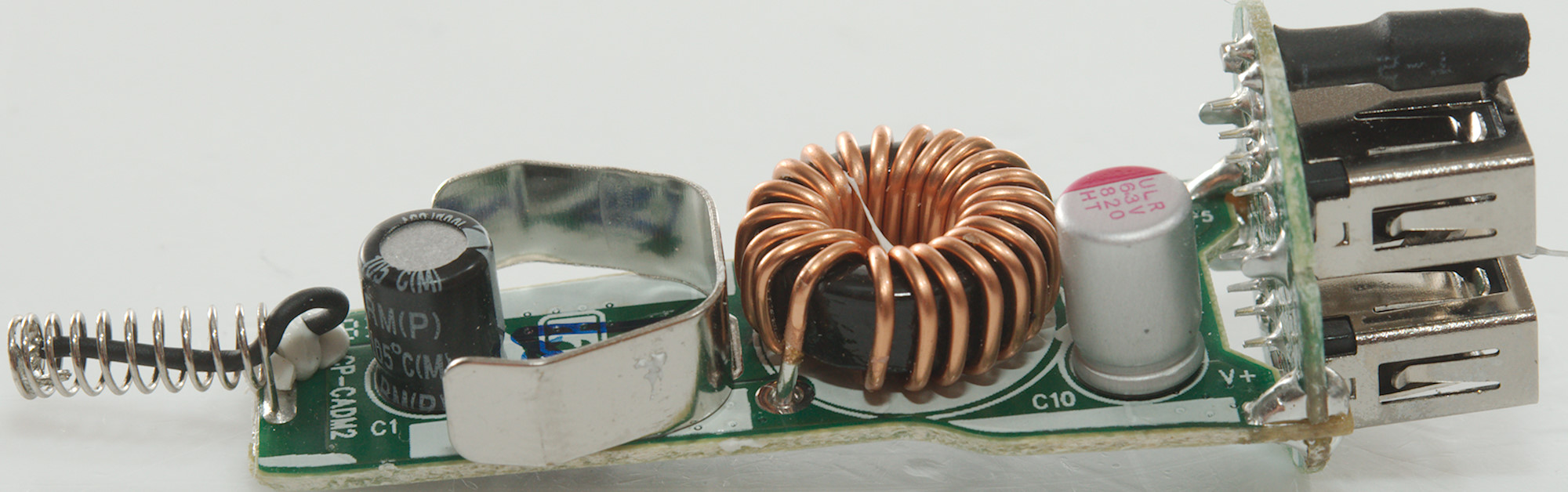
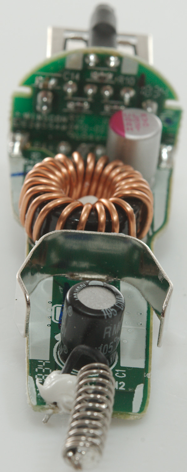
On this side we have one inductor and two capacitors.
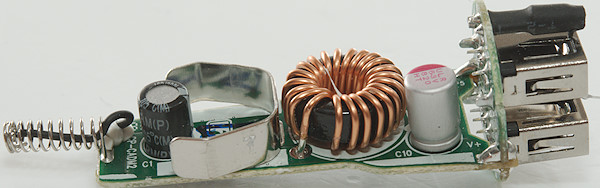
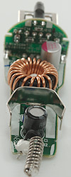
The LED is inside black shrink wrap to not light the USB connectors, but only give a small dot on the front.
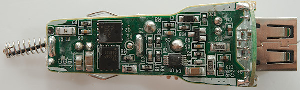
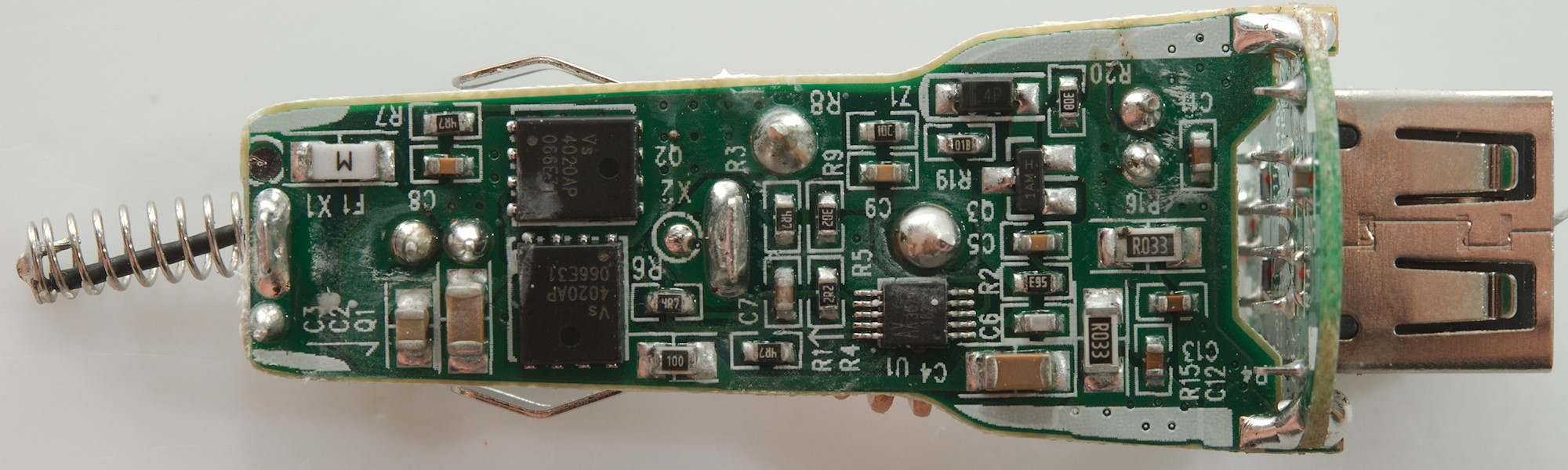
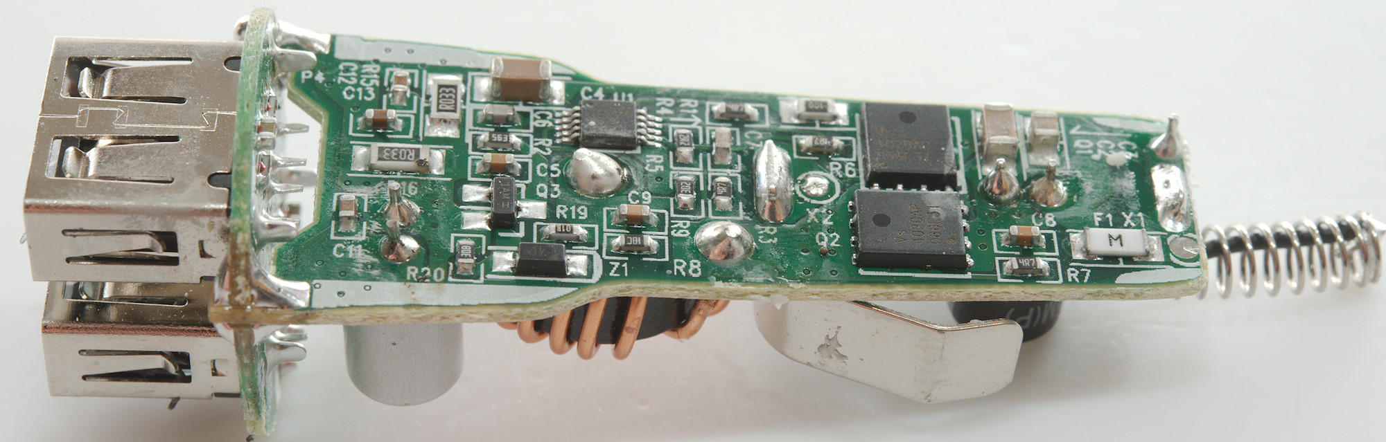
At the input is a fuse (F1 X1), the two switching transistors (Q? & Q2: Vs4020AP: 40V 60A 4mOhm), followed by a synchronous switcher chip (U1: AX3070: 40V two current limit input) with two current sense resistors (R15 & R16: 0.033ohm)
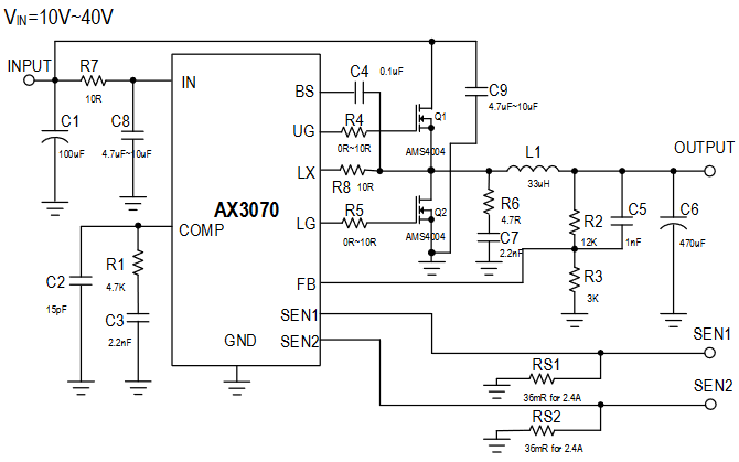
Typical circuit from the datasheet, the charger do not use exactly the same circuit.

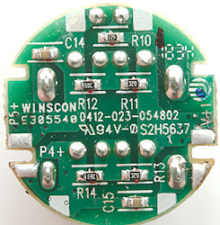
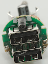
On the front circuit board is resistors for coding, there is no auto coding IC.
Conclusion
This looks like a fairly well designed car charger with lots of current, low noise and individual port protection, but I am missing a auto code chip.
Notes
Read more about how I test USB power supplies/charger
Compare car chargers and other DC supplied chargers