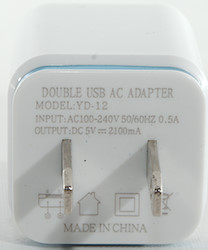
Travel Dual port usb charger YD-12
Official specifications:
- Plug type: US Plug
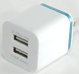
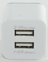
- Output: 5V 1.0A(Port 1) + 2.1A(Port 2)
- Output power: 10W
- Input: 100V-240V AC 50/60Hz
I got it from Ebay dealer tonsee_shop
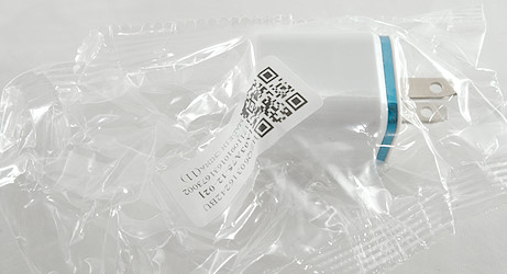
No box, just a plastic bag without any instruction sheet or usb cable.
Measurements
- Power consumption when idle is 0.11 watt
- USB output 2.1A is coded as Apple 1A
- USB output 1A is coded as Apple 1A
- Outputs are in parallel.
- Weight: 23.1g
- Size: 52 x 30.3 x 29.3mm
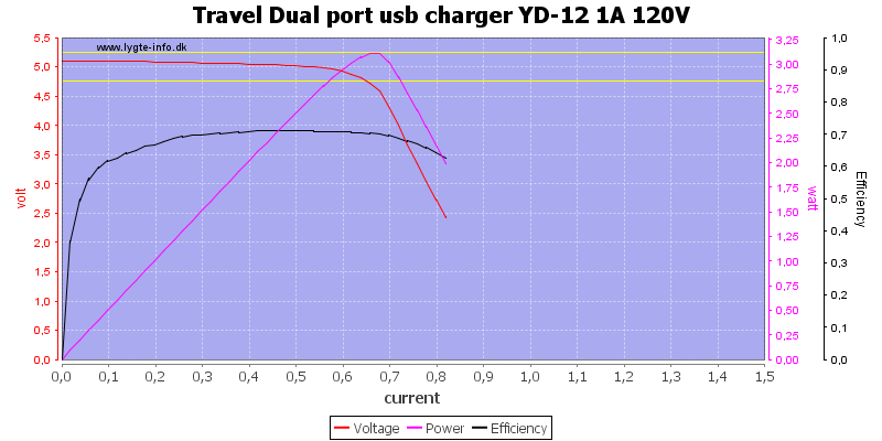
The output rating is fairly optimistic, it can only deliver on the 0.6A output.
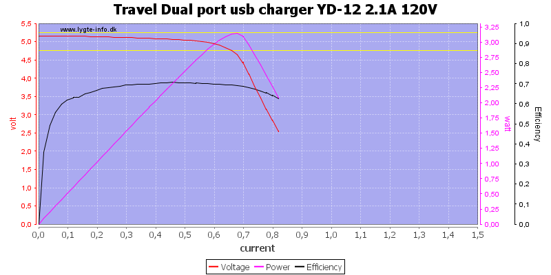
The 2.1A output is the same.
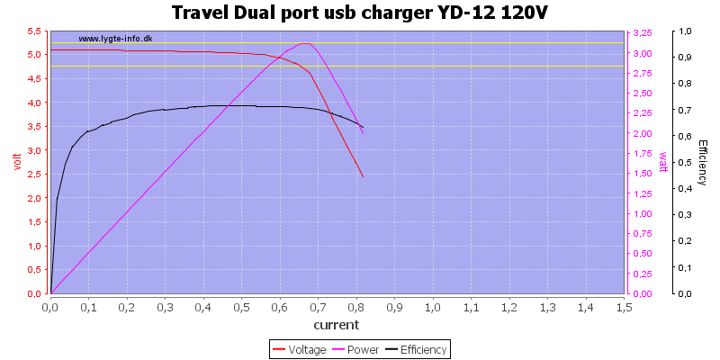
Running both outputs in parallel do not increase the power. When run at 120VAC this is a 0.6A charger.
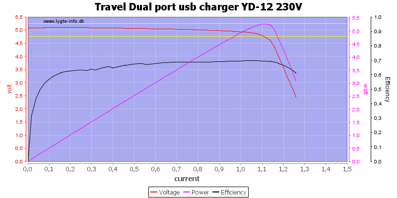
Increasing the voltage to 230VAC will increase the total output to 1.1A.
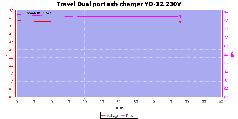
The charger could run 1 hour at 1A with 230VAC supply.
The temperature photos below are taken between 30 minutes and 60 minutes into the one hour test.
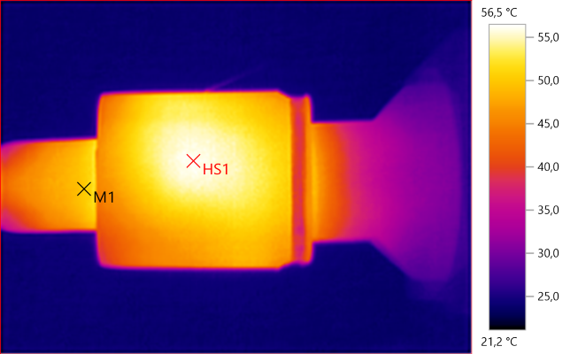
M1: 50,3°C, HS1: 56,5°C
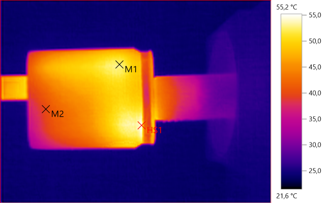
M1: 52,5°C, M2: 39,9°C, HS1: 55,2°C
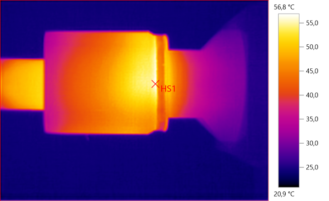
HS1: 56,8°C
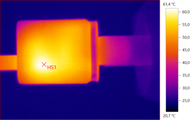
HS1: 61,4°C
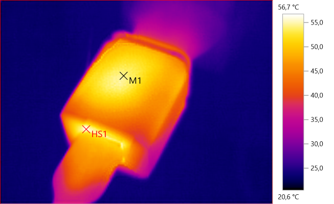
M1: 54,2°C, HS1: 56,7°C
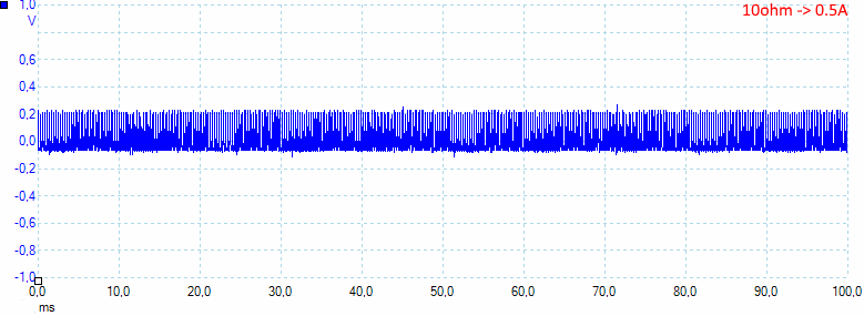
At 0.5A the noise is 59mV rms and 388mVpp.
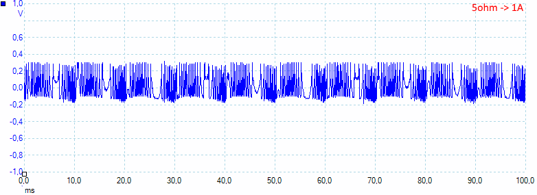
At 1A the noise is 103mV rms and 485mVpp, the noise do not look nice.
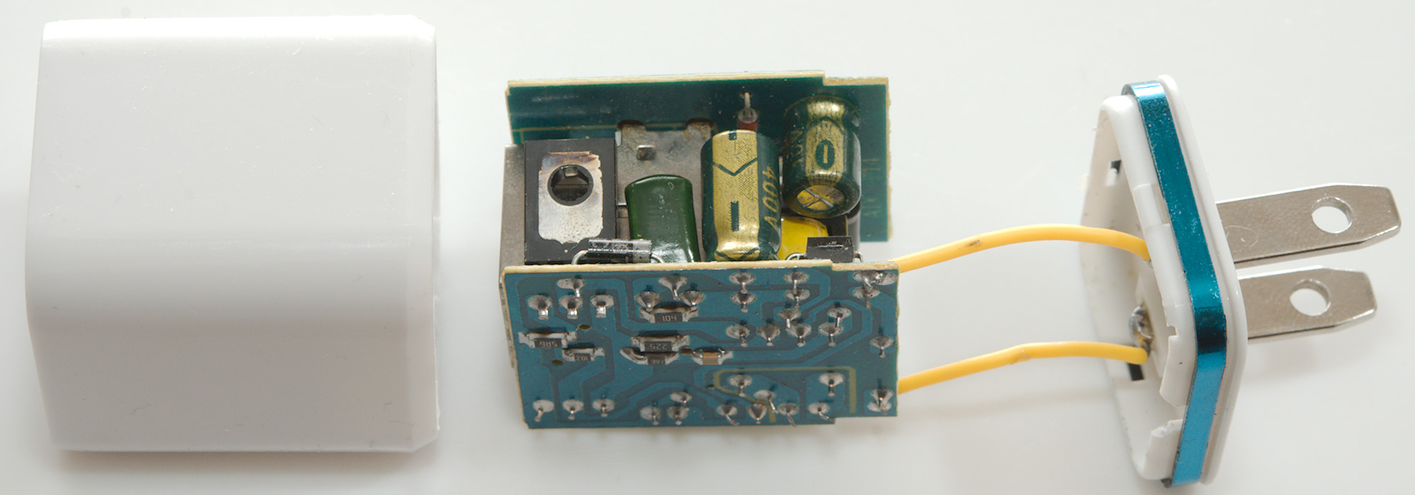
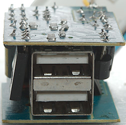
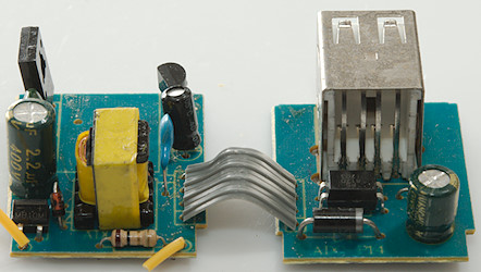
Tear down
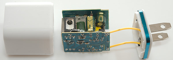
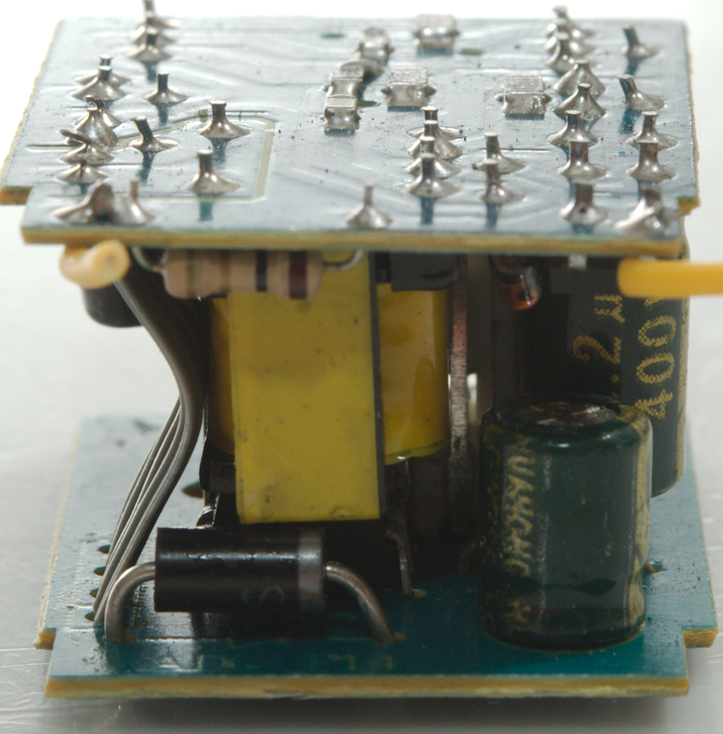
Some pressure from my vice and it popped open.
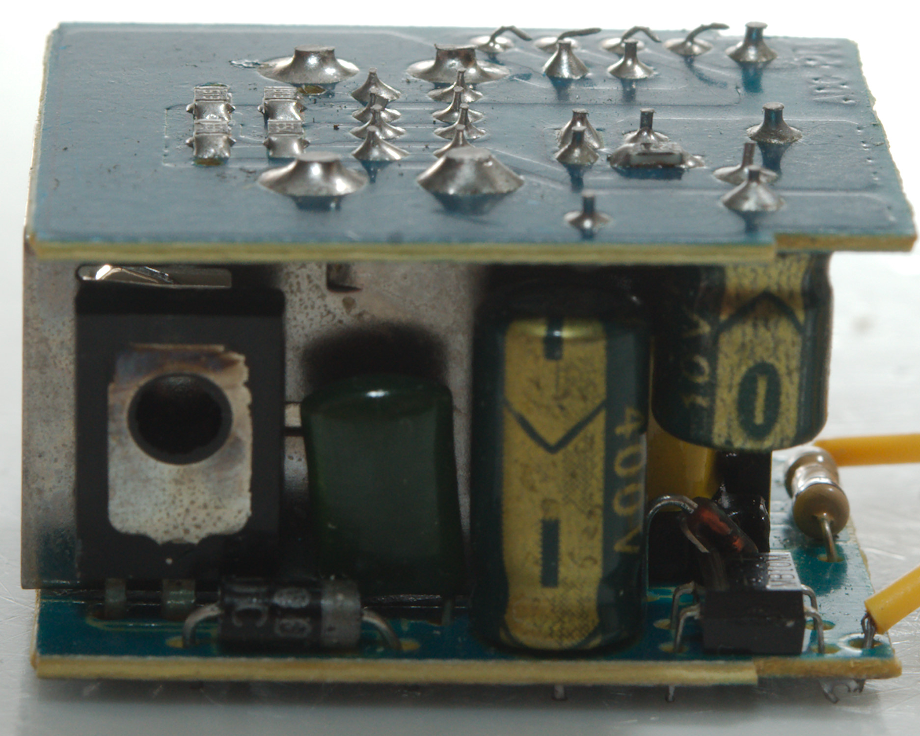
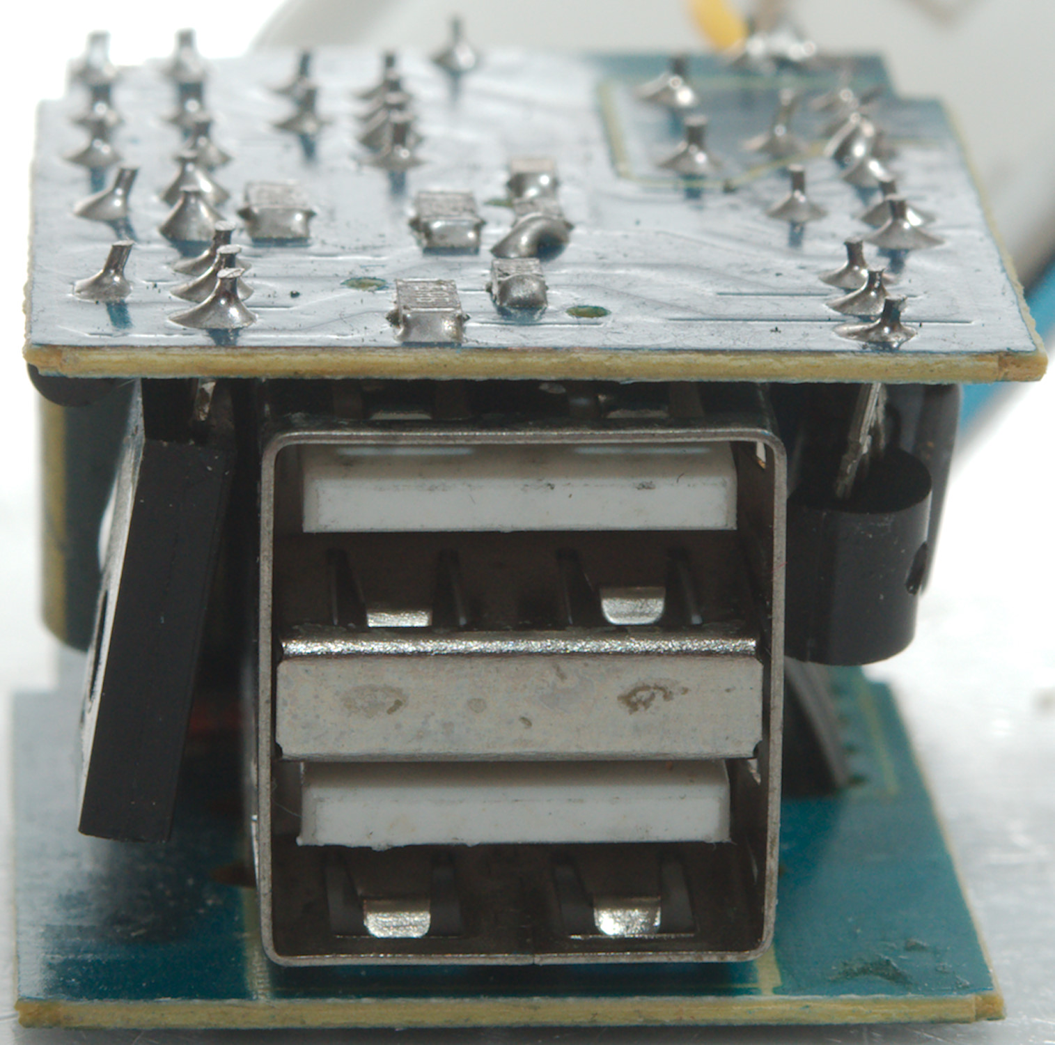
The usb connector is directly connected to the metal on whatever is being charged and the safety rules says that air distances to mains part must be at least 4 mm. The legs from the mains switching transistor to the usb connector do not live up to that.
The small transistor is also on the mains side and again the distance is very short to the usb connector.

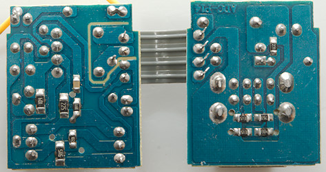
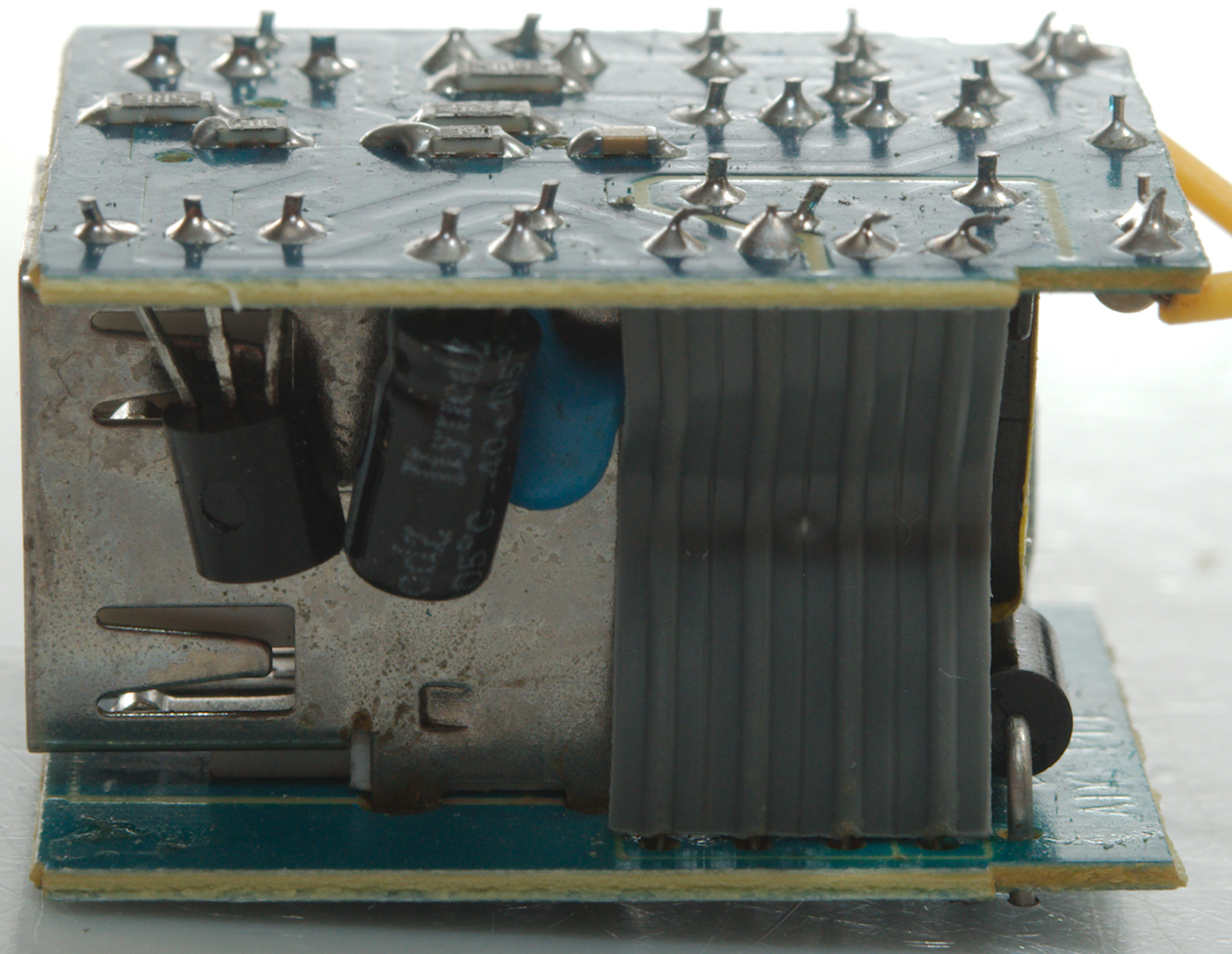
The circuit is distributes on two circuit board, one mostly for mains and one mostly for low voltage, but the overlap is very bad with low safety distances.
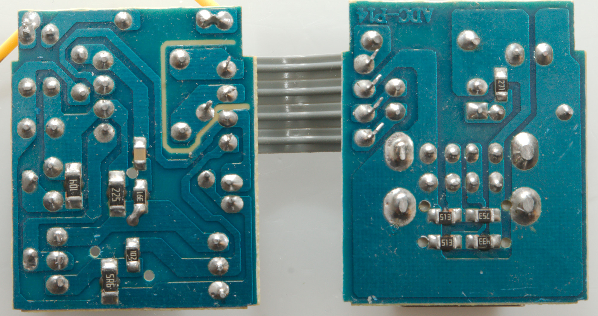
The two usb connectors shares the coding resistors, i.e. the circuit do not even support different coding on the two connectors!

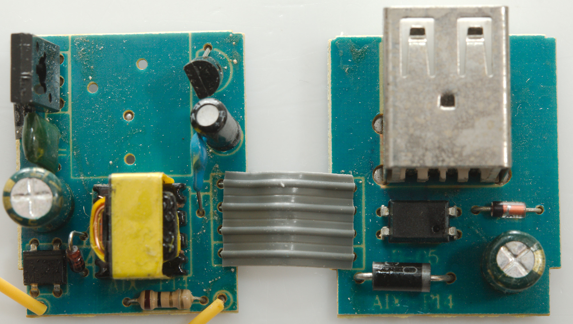
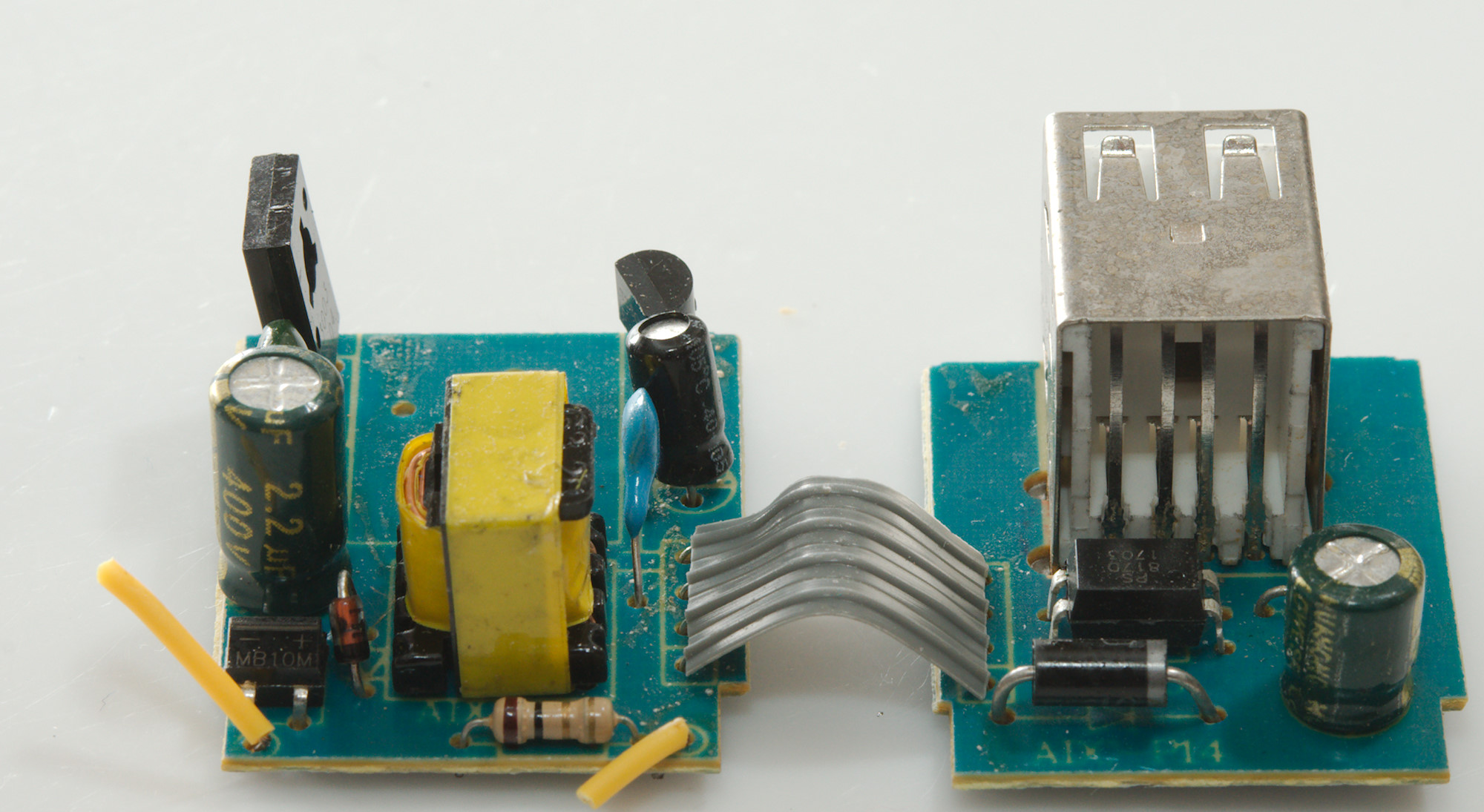
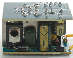
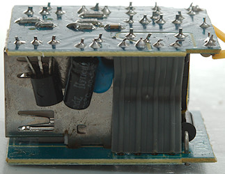
A normal resistor is used, instead of a fuse and it has a very tiny rectifier bridge for mains. The transformer secondary goes to the circuit board and is transferred to the other circuit board through a flat flex cable.
The same cable has the return signal from the opto feedback (That signal is at mains level.
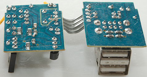
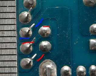
I have marked mains with red and low volt with blue, there is supposed to be more than 6mm between them, here is less than 1mm
The charger failed both the 2830 volt and 4242 volt test, i.e. it is not safe to use anywhere.
Conclusion
This charger is a real death trap, stay away.
Notes
Index of all tested USB power supplies/chargers
Read more about how I test USB power supplies/charger
How does a usb charger work?