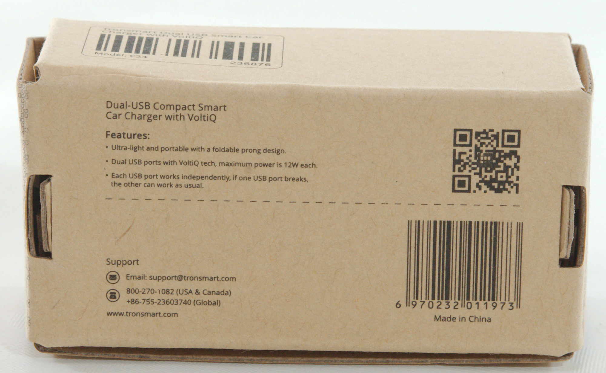
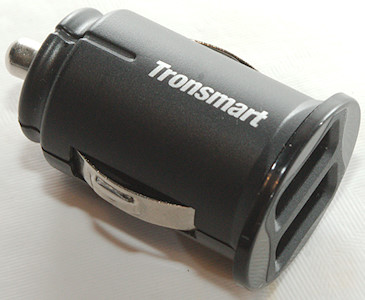
Tronsmart C24 Dual USB compact car charger
Official specifications:
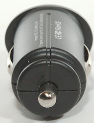
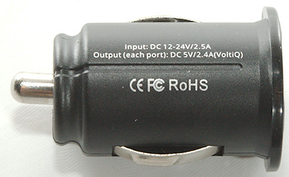
- Input: 12-24V DC
- Output (Each port): 5V 2.4A (VoltiQ).
- Each port functions independently
I got it from a reader
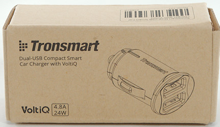
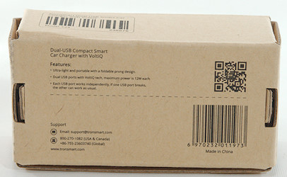
I got this charger in a cardboard box, it only contained the charger.
Measurements
- Power consumption when idle is 0.03 watt (2.5mA) at 12V and 0.06 watt (2.4mA) at 24V
- Usb ports is auto coding with Apple 2.4A as max.
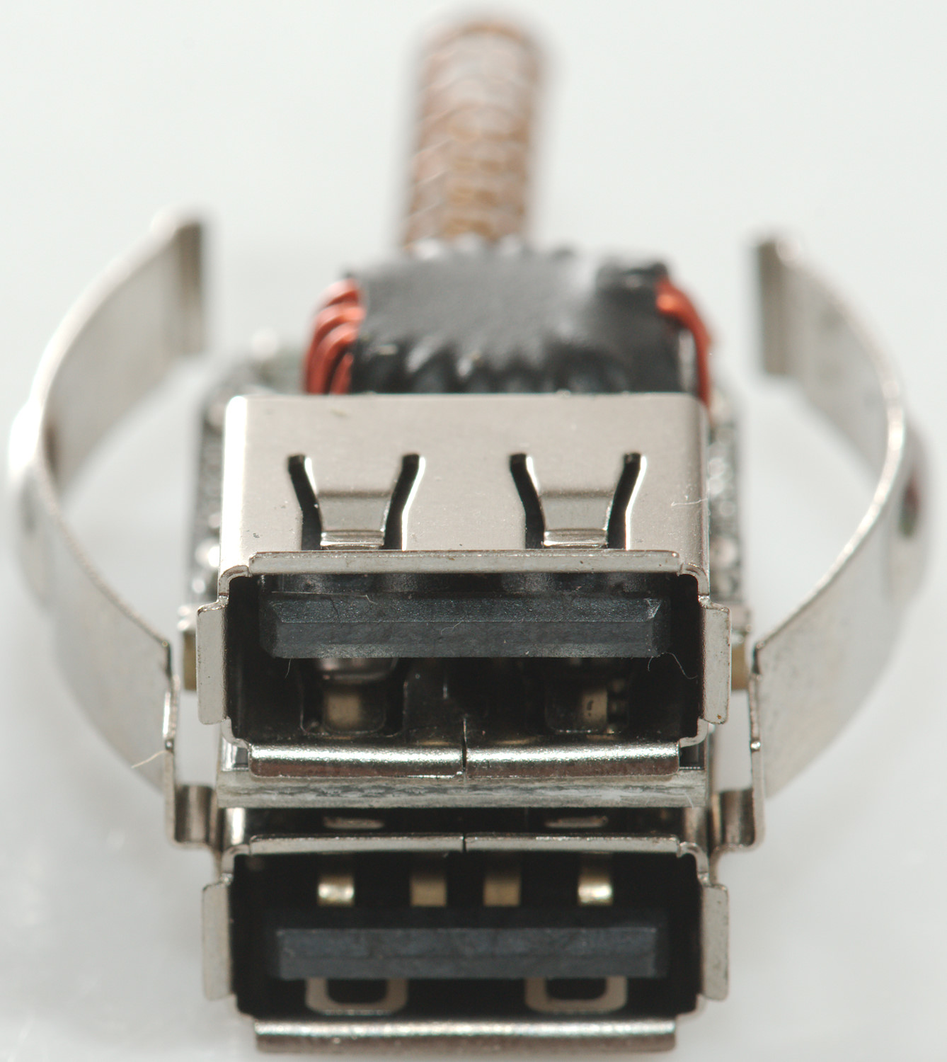
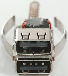
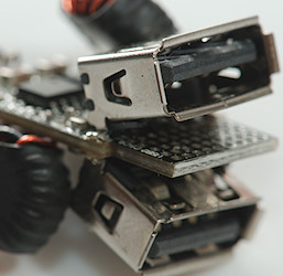
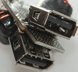
- The two ports are rotated 180° to each other.
- Weight: 13.7g
- Length: 41.3mm
- Front: 21.4 x 26.0mm

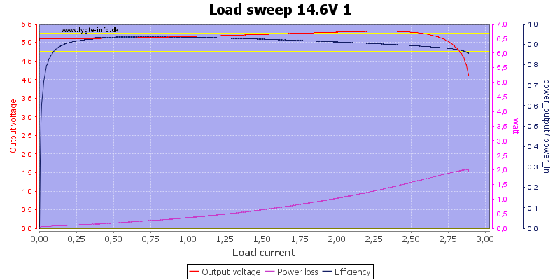
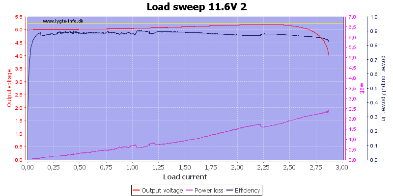
Output voltage will increase slightly when loaded, the overload protection kicks in at about 2.8A
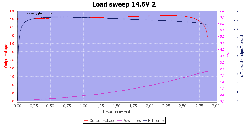
The second output looks similar.
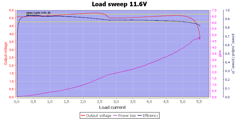
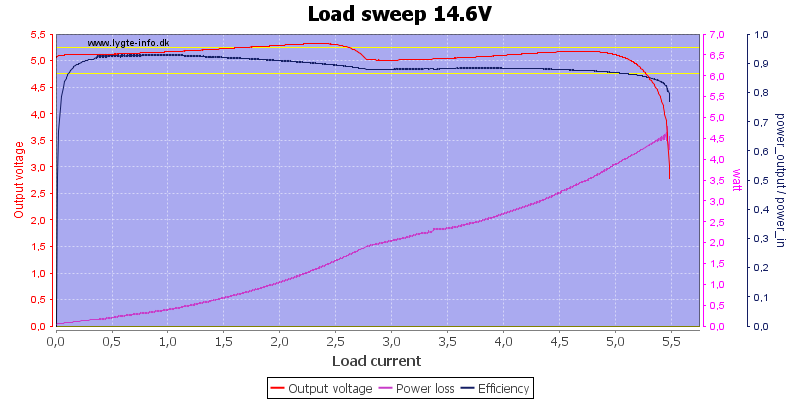
Due to small voltage differences between the two outputs, the first one handles current up to near overload and then get supplemented by the second channel. Total current is 5.5A

Total output current is a bit lower at 24V
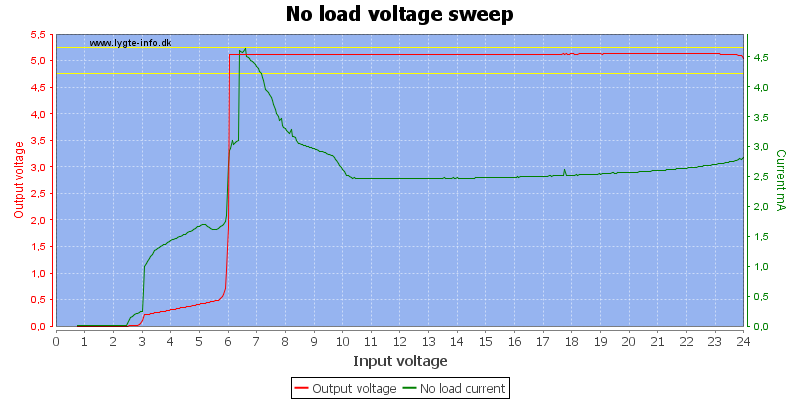
The charger needs a few mA for idle current.
The normal usb output needs about 2.2A at 12V to supply 2x2.4A on usb output.
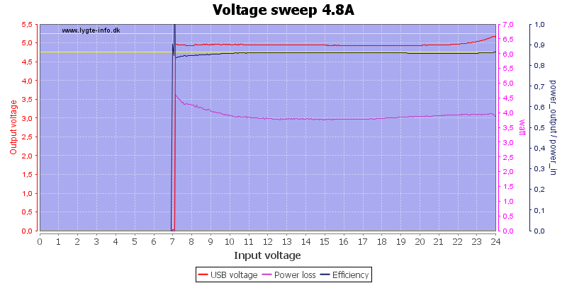
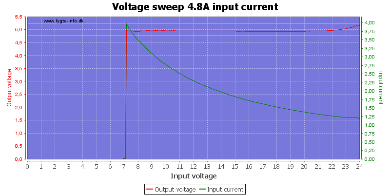
And the output will be stable down to 7 volt input.
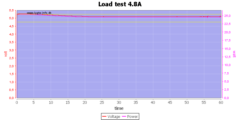
There was no problem running 1 hour with full load.
The temperature photos below are taken between 30 minutes and 60 minutes into the one hour test.
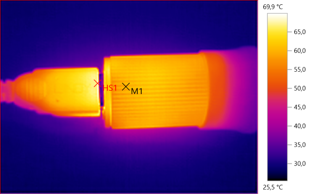
M1: 59,6°C, HS1: 69,9°C
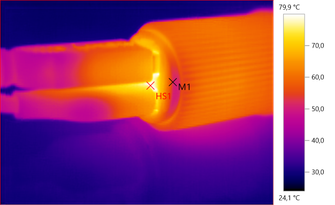
M1: 52,4°C, HS1: 79,9°C
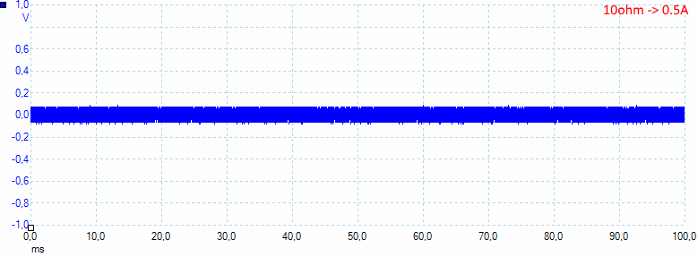
The noise at 0.5A is 51mV rms and 179mVpp
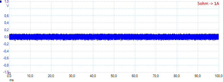
The noise at 1A is 57mV rms and 221mVpp
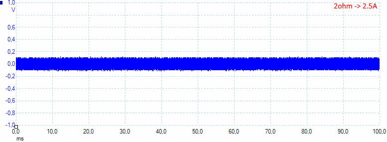
The noise at 2.5A is 74mV rms and 247mVpp.
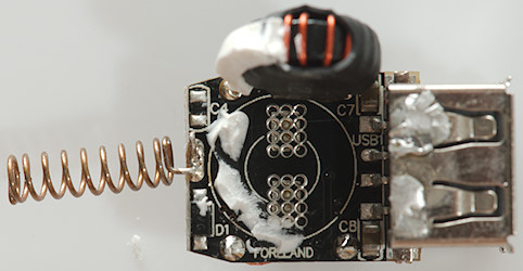
Tear down
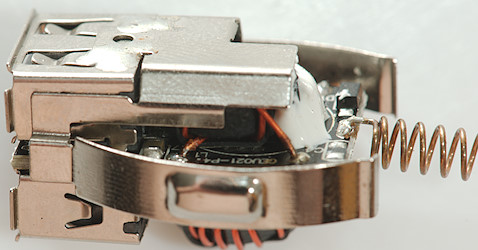
It was fairly easy to pop the lid on it.

And then I could remove the electronic.
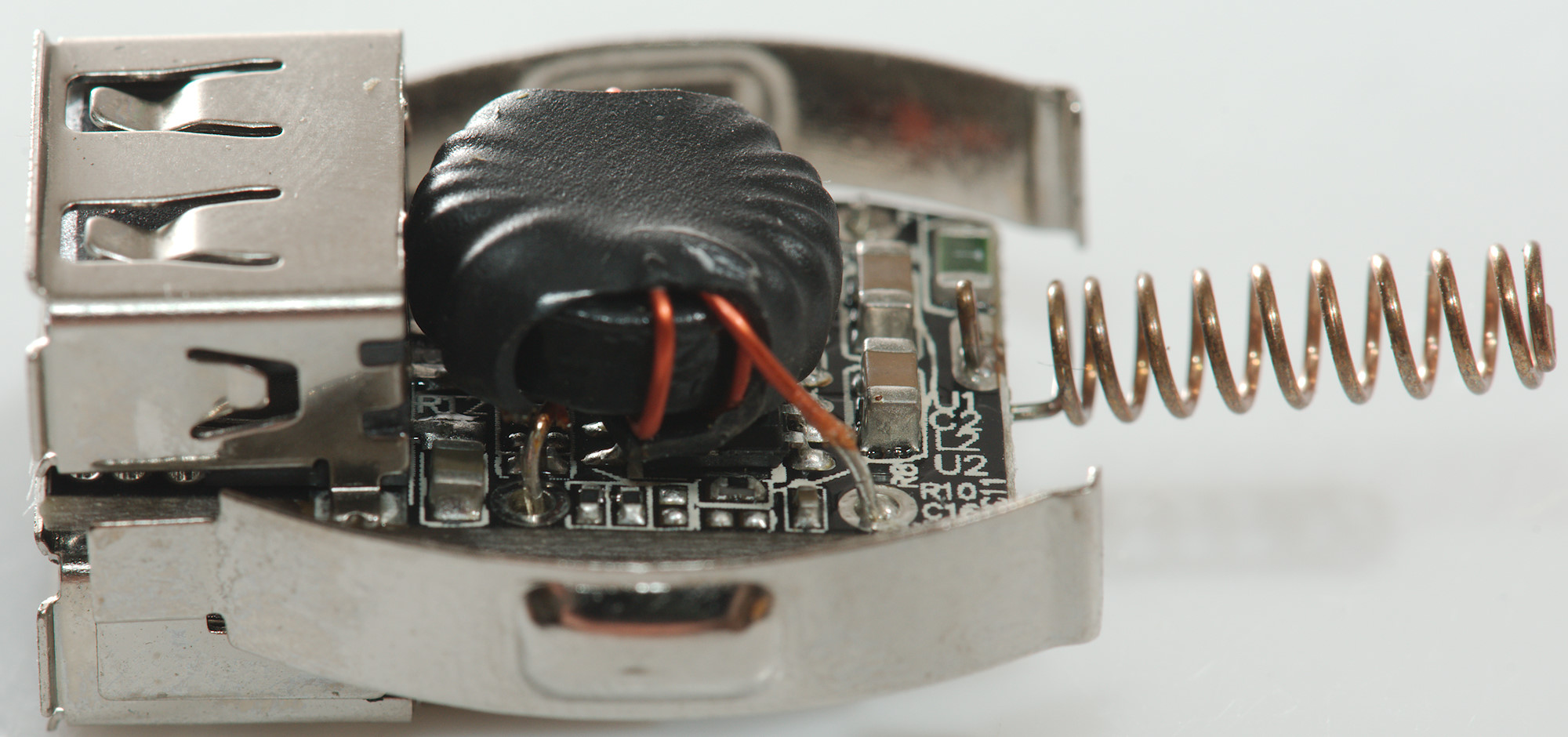
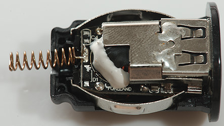
It has a lid on some of the electronic
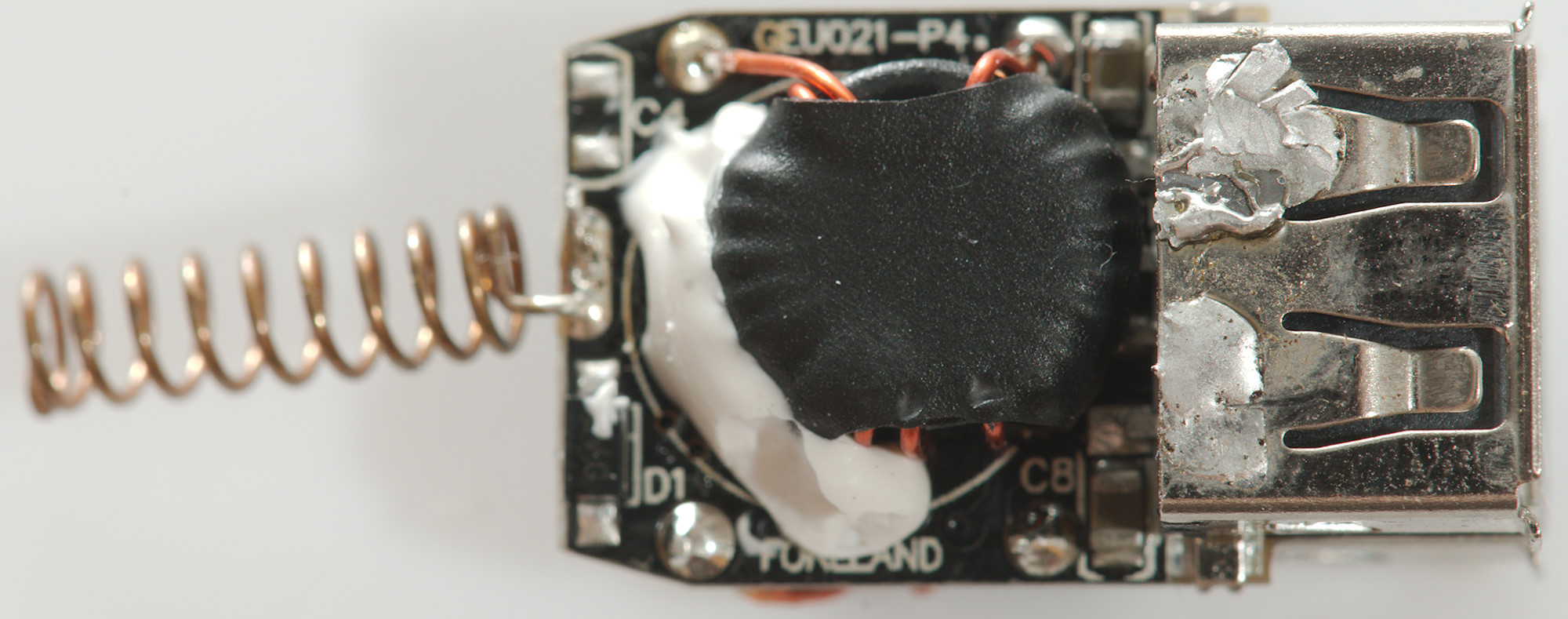
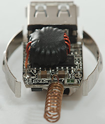
The lid could be removed with a solder iron, it was the connection for the minus springs. There is only a inductor and a diode visible on this side.
And nothing is hidden under the inductor.

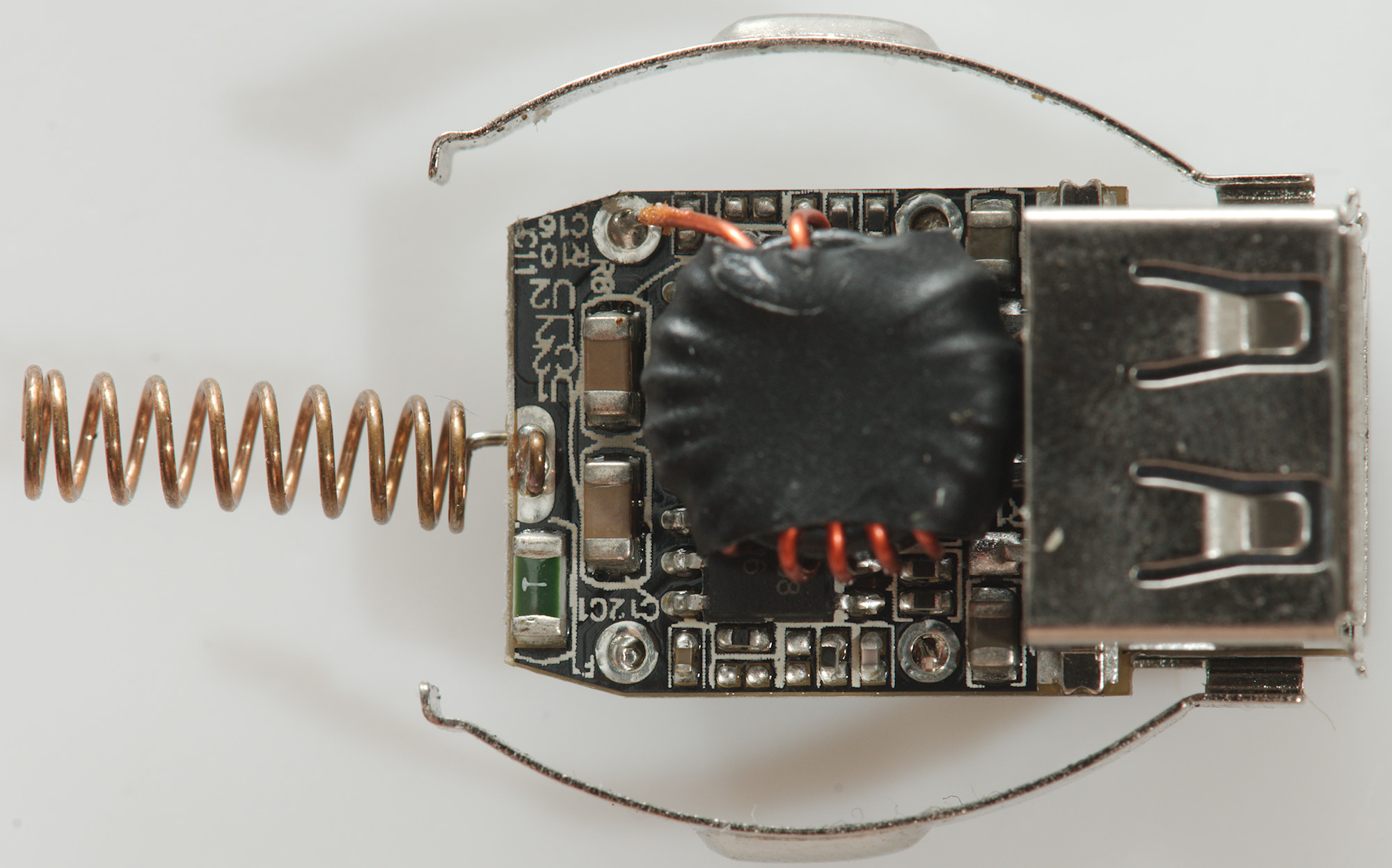
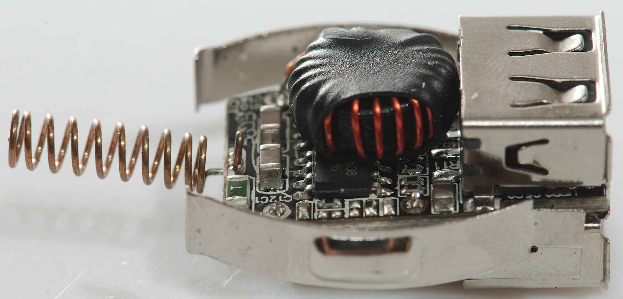
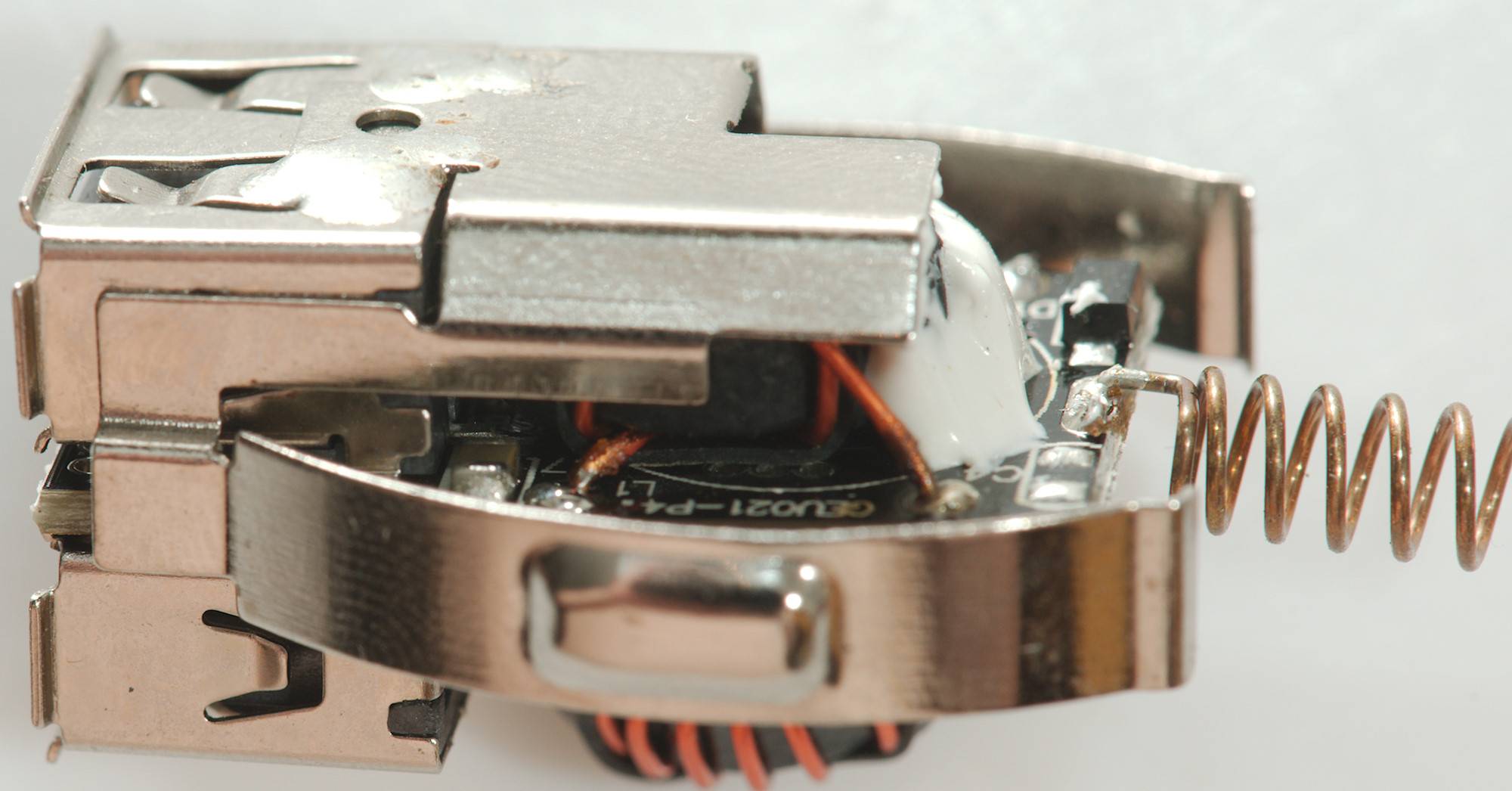
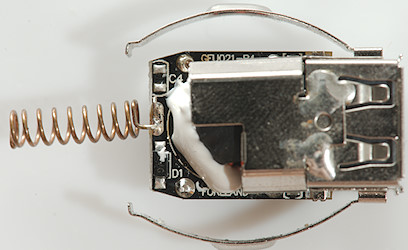
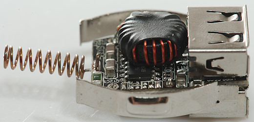
This side also contains an inductor, each output has its own switcher.
Notice the green fuse at the input.
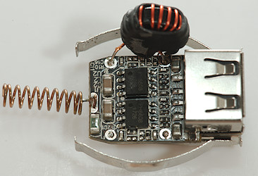
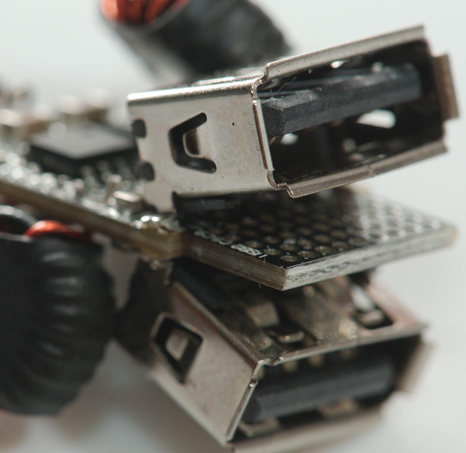
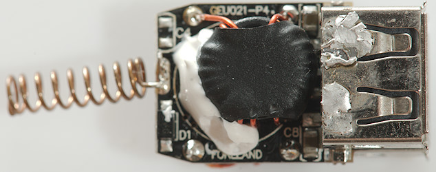
A look under the inductor shows two chips, one for each output. I cannot see any high power diode, this means it must be inside the chips with a synchronous rectification.
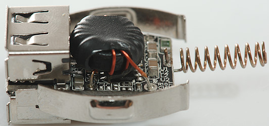
I was missing the auto coding chip, I even checked under the usb connectors, but did not find any, this means the chips must be specially designed for this with build-in auto coding for usb.
Being a 12V device there is no need to test with high voltages.
Conclusion
This is a very compact universal usb car charger and it will charge nearly anything at maximum speed. With two separate circuits it does also have overload protection on each port. This type of short model can be a bit difficult to remove from the car socket.
Notes
The usb charger was supplied by a reader for a review.
Index of all tested USB power supplies/chargers
Read more about how I test USB power supplies/charger