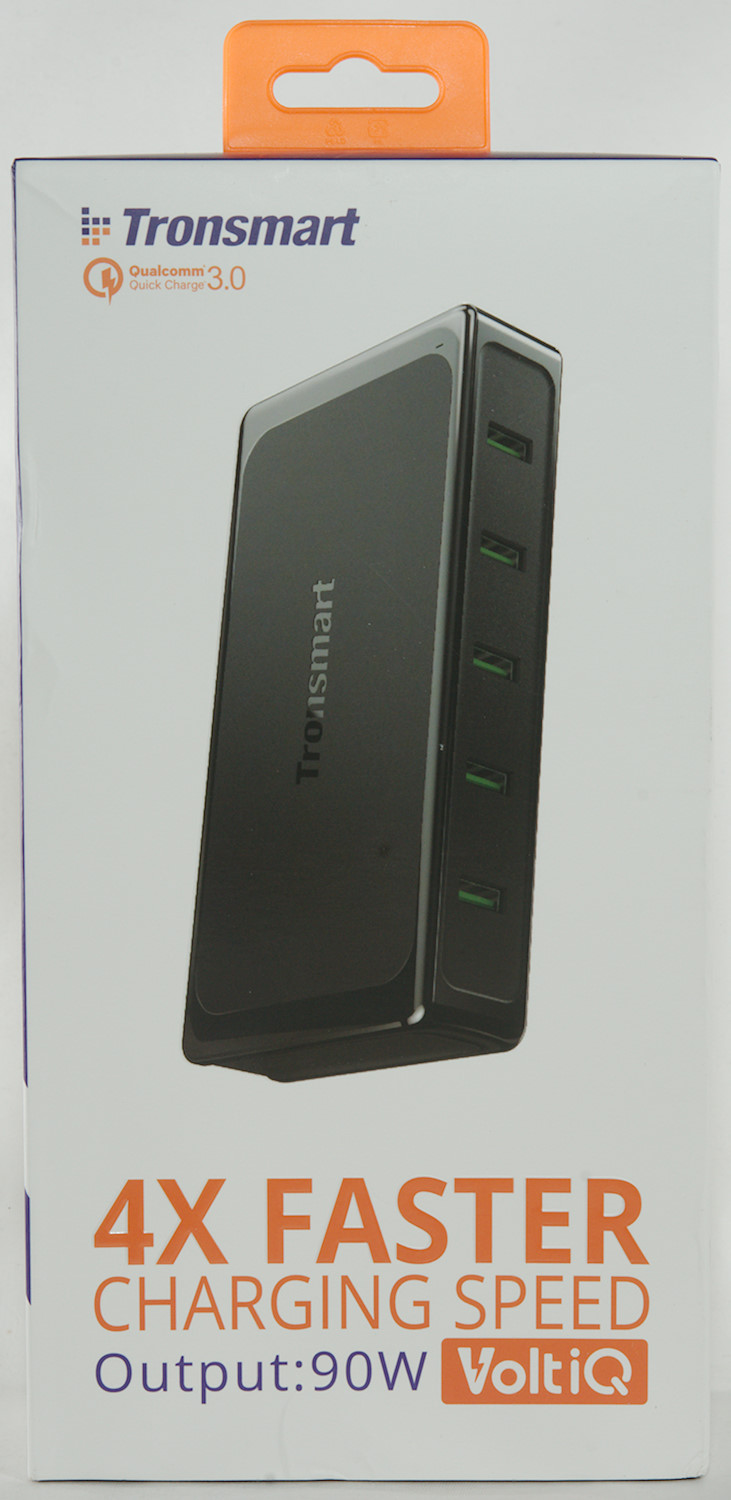
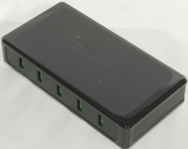
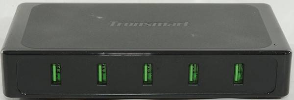
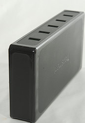
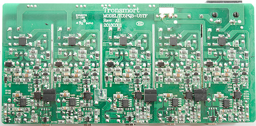
Tronsmart Titan plus 5 port QC charger U5TF
Official specifications:
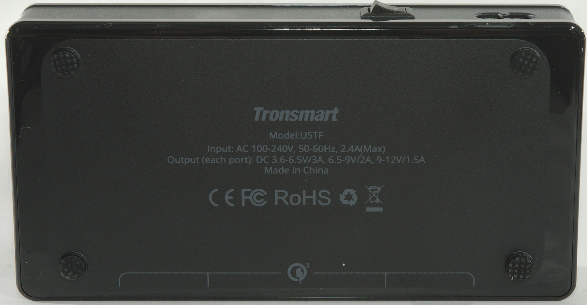
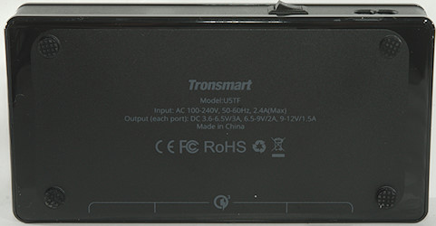
- Model: U5TF
- Technology: Qualcomm Quick Charge 3.0 & VoltiQ & Huawei FCP
- Input: AC 100-240V, 50-60HZ, 2.4A (Max)
- Output: Max 5-6.5V/3A, 6.5-9V/2A, 9-12V/1.5A; 5V/2.4A
- Total Power: 90W
- Material: PC
- Size: 159*81*29 mm
- Weight: 300g
- Certifications CE, FCC, RoHS
I got it from ebay dealer: thetoptens
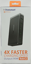
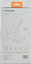
The charger arrived in a cardboard box.
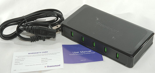
The box contained the charger, a mains cable, a instruction sheet and the warranty card.
Measurements
- Power consumption when idle is 0.2 Watt
- All USB outputs are auto coding with Apple 2.4A, Samsung, DCP, QC3, Samsung-AFC, Huawei-FCP
- Minimum QC3 voltage is 4.3V
- Weight: 295g
- Size: 159 x 81 x 30.2mm
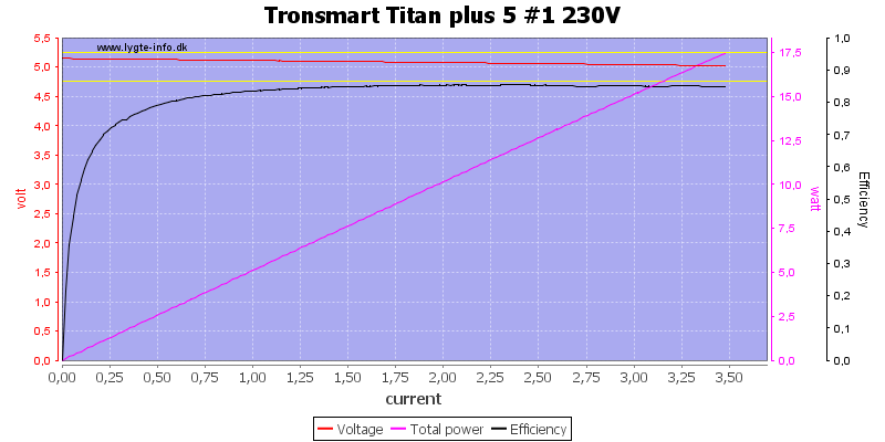
At 230VAC the overload protection kicks in at 3.5A on all outputs.

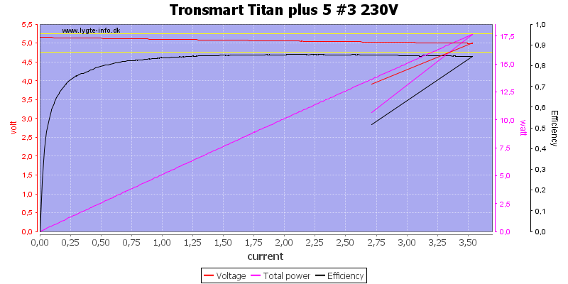

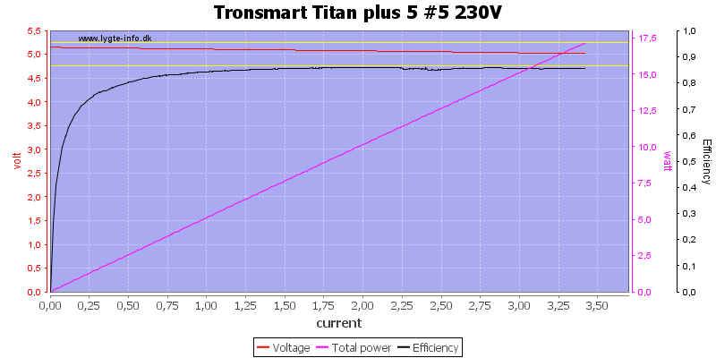
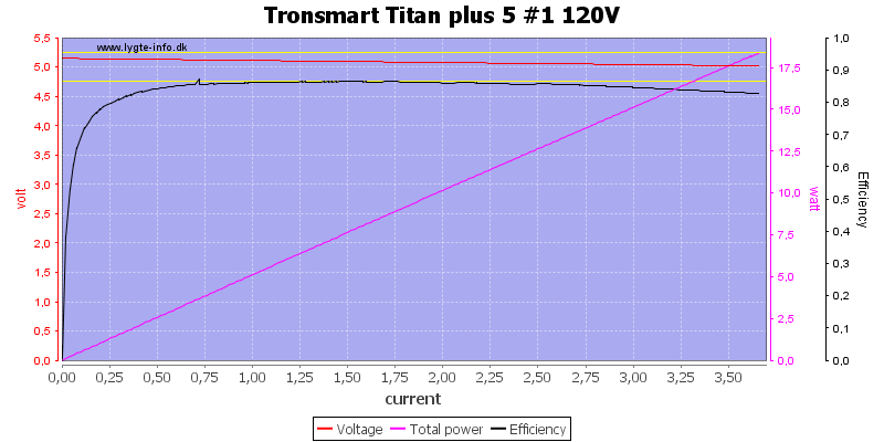
At 120VAC the current is slightly higher.
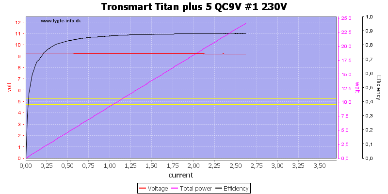
At 9V the overload protection is at 2.6A
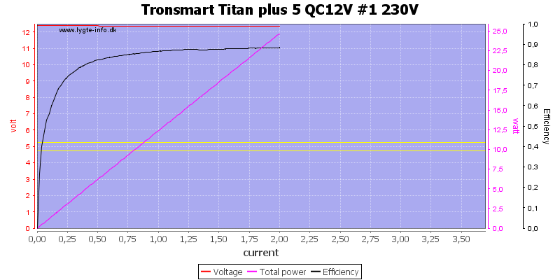
And at 12V the overload protection is at 2A
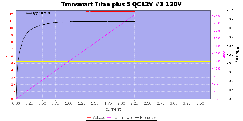
Again 120VAC means slightly higher current.
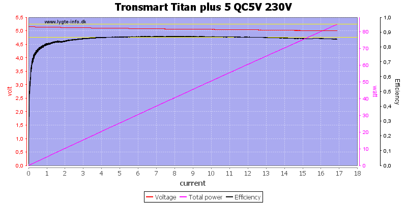
Running all outputs in parallel (Each with its own load) at 5V the maximum current is 17A
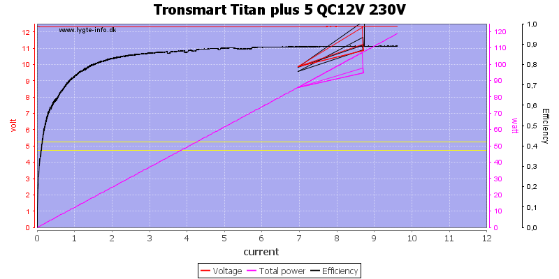
At 12V the maximum current is nearly 10A.
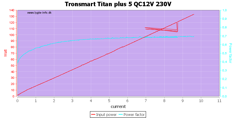
Power factor (PF) is relevant at higher power, this power supply has not compensated it to about 1.
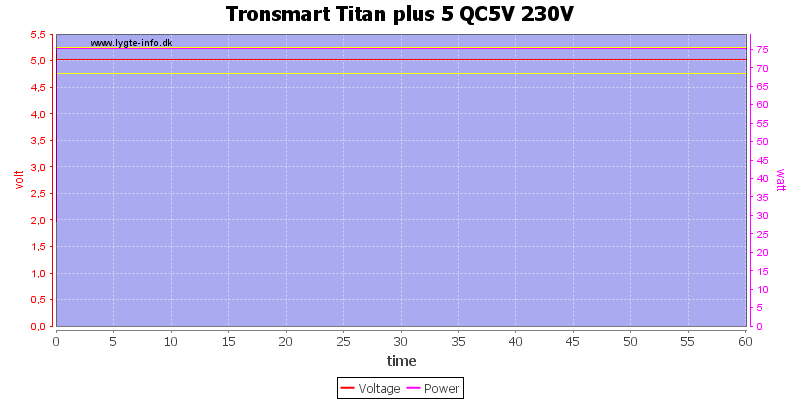
The charger had no problem running one hour with 5*3A -> 15A total output.
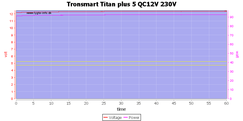
The charger could also handle 12V 1.5A*5, but the output voltage did increase a bit when the charger got warm.
Voltage is calculated as an average for all 5 outputs in both tests.
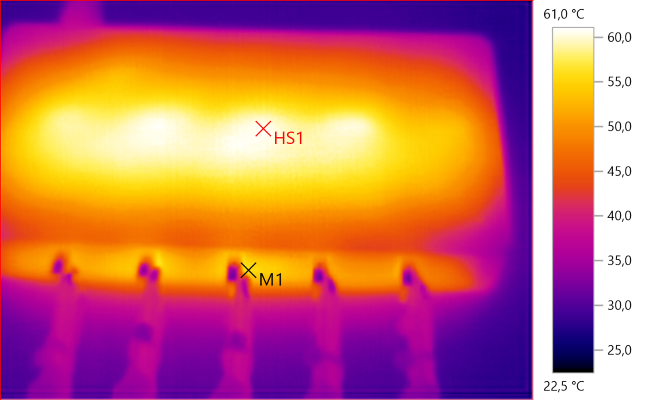
The temperature photos below are taken between 30 minutes and 60 minutes into the one hour test.
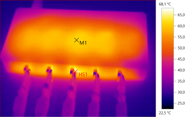
M1: 61.0°C, HS1: 68.1°C
5V 3A output. All the heat patches on the top are the transformers.
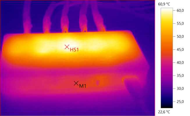
M1: 42.2°C, HS1: 60.9°C
5V 3A output.
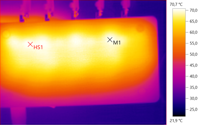
M1: 70.3°C, HS1: 70.7°C
5V 3A output, here the heat is from the synchronous rectifiers and the transformers.
M1: 55.5°C, HS1: 61.0°C
12V 1.5A output, the temperature of the transformers are about the same at this current as with 5V 3A.
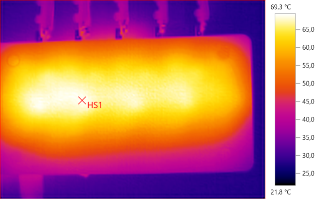
HS1: 69.3°C
12V 1.5A output, but the rectifier do adds as much heat, here it is mainly the transformers.
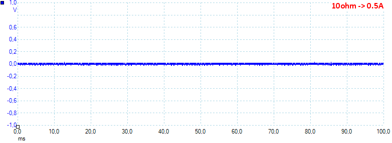
At 0.5A the noise is 12mV rms and 74mVpp.
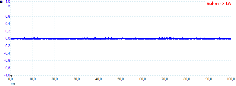
At 1A the noise is 44mV rms and 218mVpp.
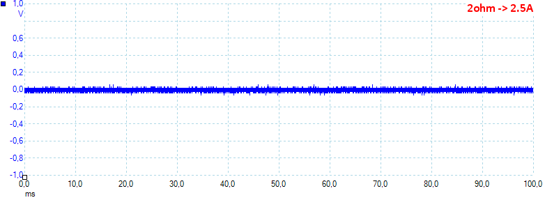
At 2.5A the noise is 31mV rms and 234mVpp.
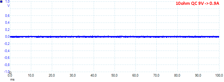
At 9V 0.9A the noise is 15mV rms and 113mVpp.
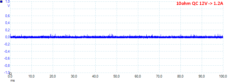
At 12V 1.2A the noise is 20mV rms and 232mVpp, all noise looks fairly low
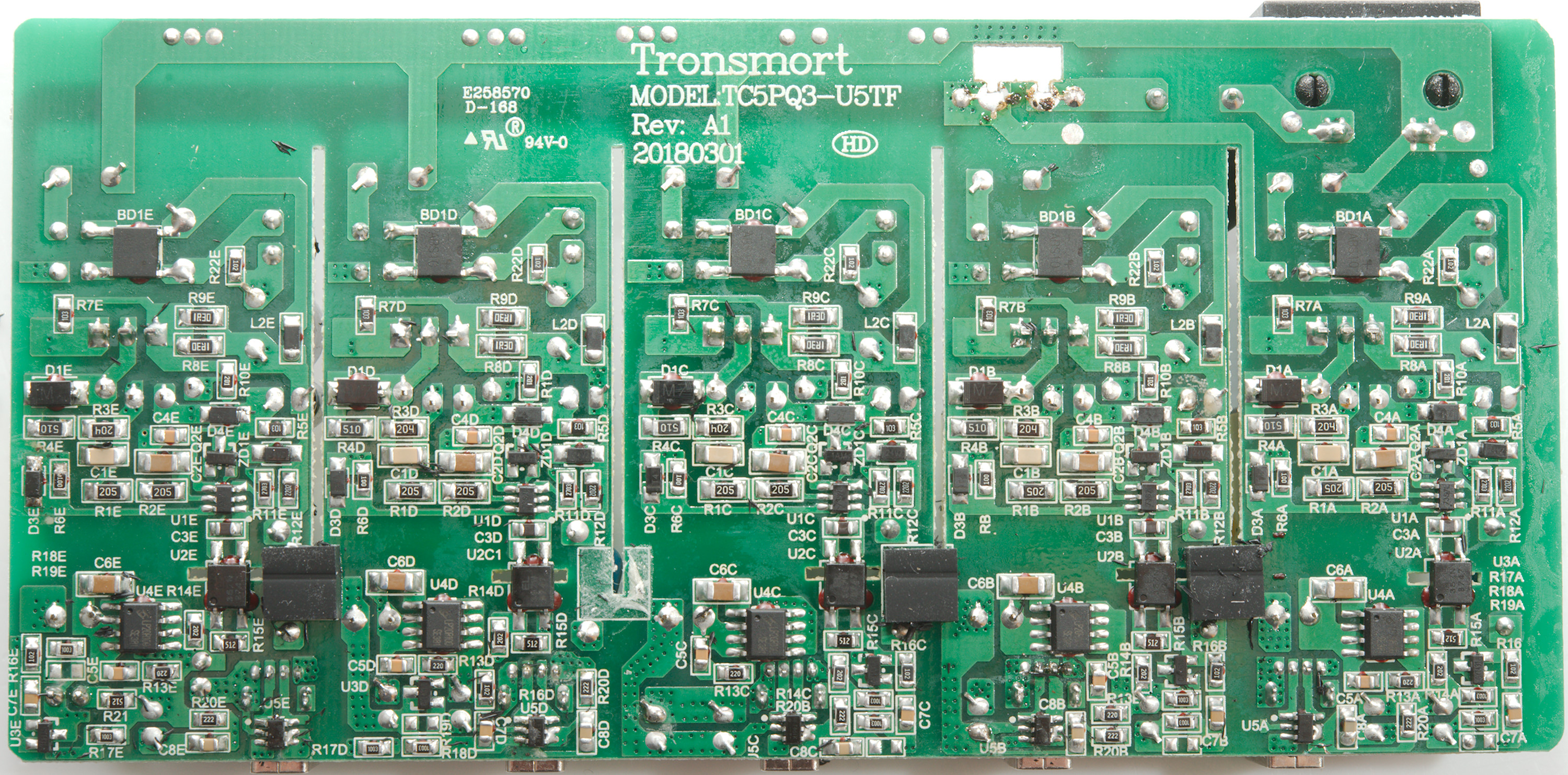
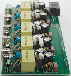
Tear down
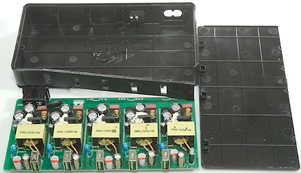
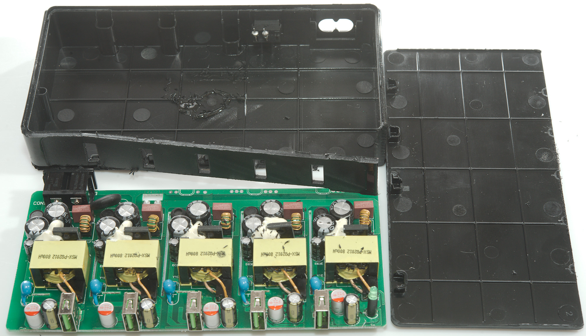
There was no obvious seams on the enclosure and I decided to cut the front off, but the lid was the bottom.
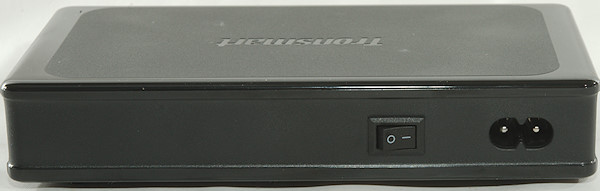
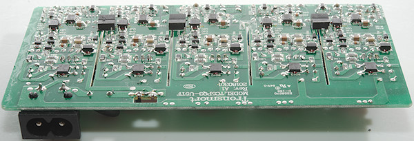
The power switch is mounted from the outside and soldered to the circuit board when it is mounted.
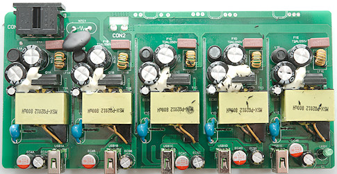
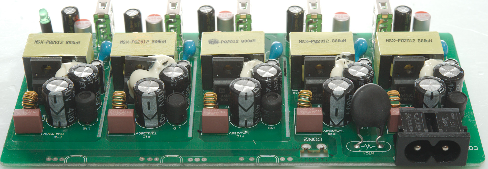
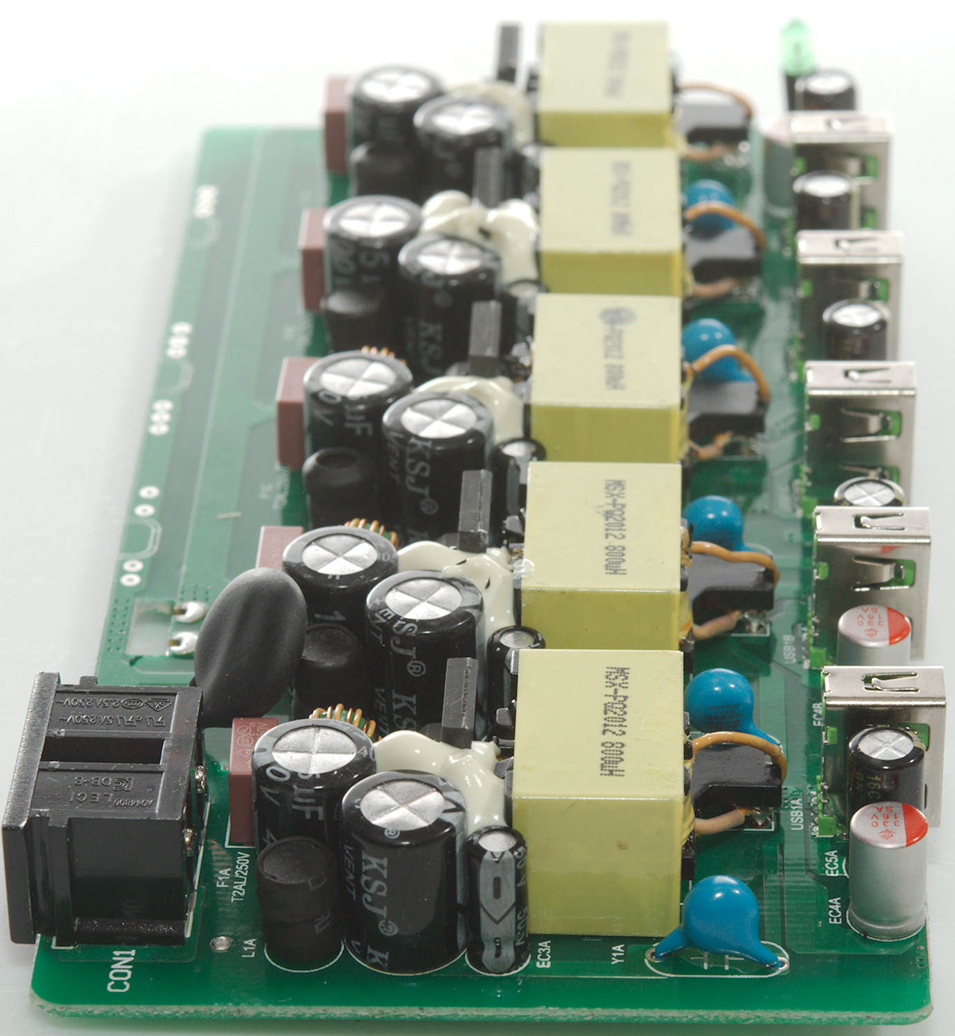
The circuit is five separate QC chargers, the only common parts is the mains switch and the inrush current limiter (NTC1). Part numbers add a letter depending what output then are for (A-E).
Each input has its own fuse (F1) followed by a common mode coil (LF1). There are two smoothing capacitors (EC1 & EC2?) with a inductor (L1) between. The mains switcher transistor (Q1: A4N65H 650V 4A) is a fully isolated TO220 package.
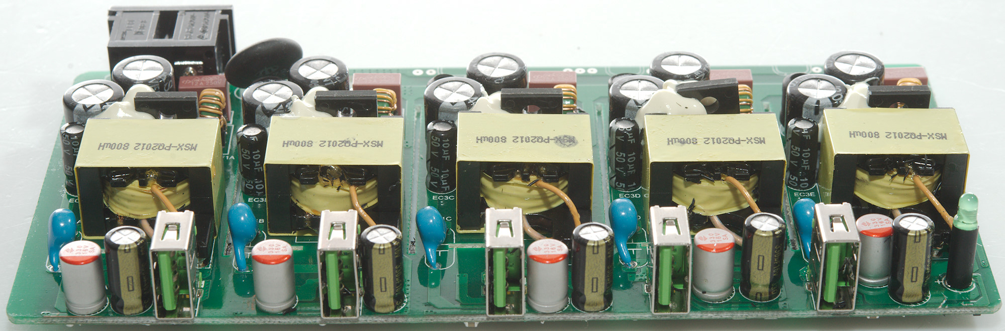
Next to the transformer is a safety capacitor (Y1). The power LED is on output E.
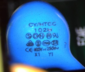
I wondered about the size of the safety cap, a common used value is 2.2nF, here it is 5 pieces of 1nF, because you will only touch one one output at a time the leakage current is small.

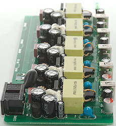

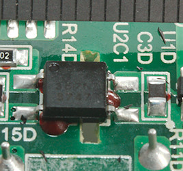
On this side is the bridge rectifier (BD1), the switcher controller (U1: Marked 73S7L). Being QC a optocoupler is needed (U2: EL357N 3750V isolation). On the low volt side is the synchronous rectifier (U4: LP20R100), the QC controller (U5: FT4) and the usual reference (U3: CYT431A)
There is no problem with isolating distance, it is more than enough.
Testing with 2830 volt and 4242 volt between mains and low volt side (I did it on each output), did not show any safety problems.
Conclusion
The is five high quality QC charger in one enclosure, then are auto coding with support for many protocols, low noise and can deliver a lot of current, but with individual overload protection. Efficiency is good. I did not see any safety issues.
Notes
Index of all tested USB power supplies/chargers
Read more about how I test USB power supplies/charger
How does a usb charger work?