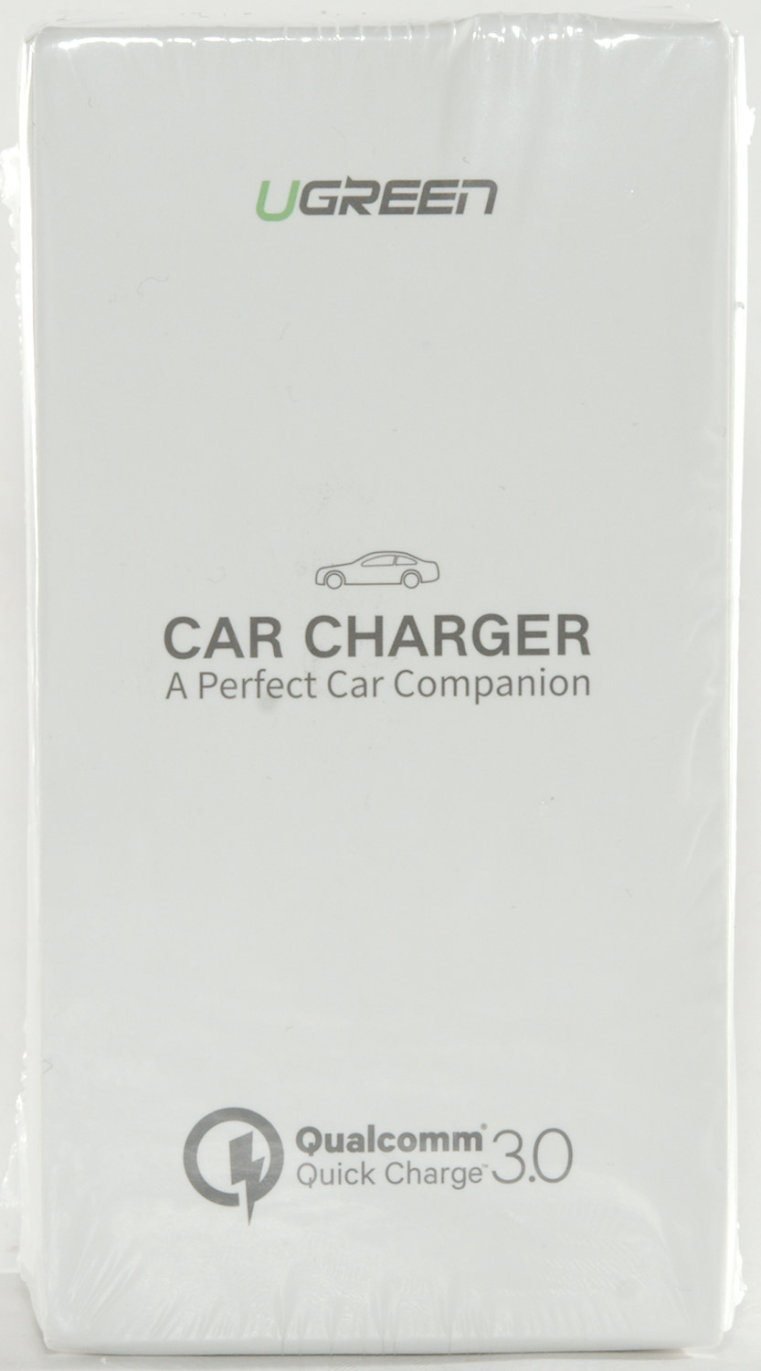
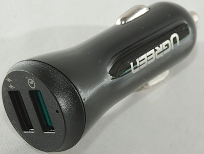
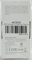
UGreen Car Charger QC CD114
Official specifications:
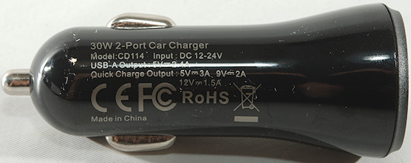
- Input: DC 12-24V
- USB A Output: 5V---2.4A;
- QC3.0 Output: 5V---3A, 9V---2A, 12V---1.5A;
- Total Output Power: 30W Max;
- Dimensions: 28x72 (mm).
I got it from ebay dealer: ugreen_flagship_store
It arrived in a white cardboard box with some text on, but no specifications.
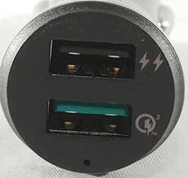
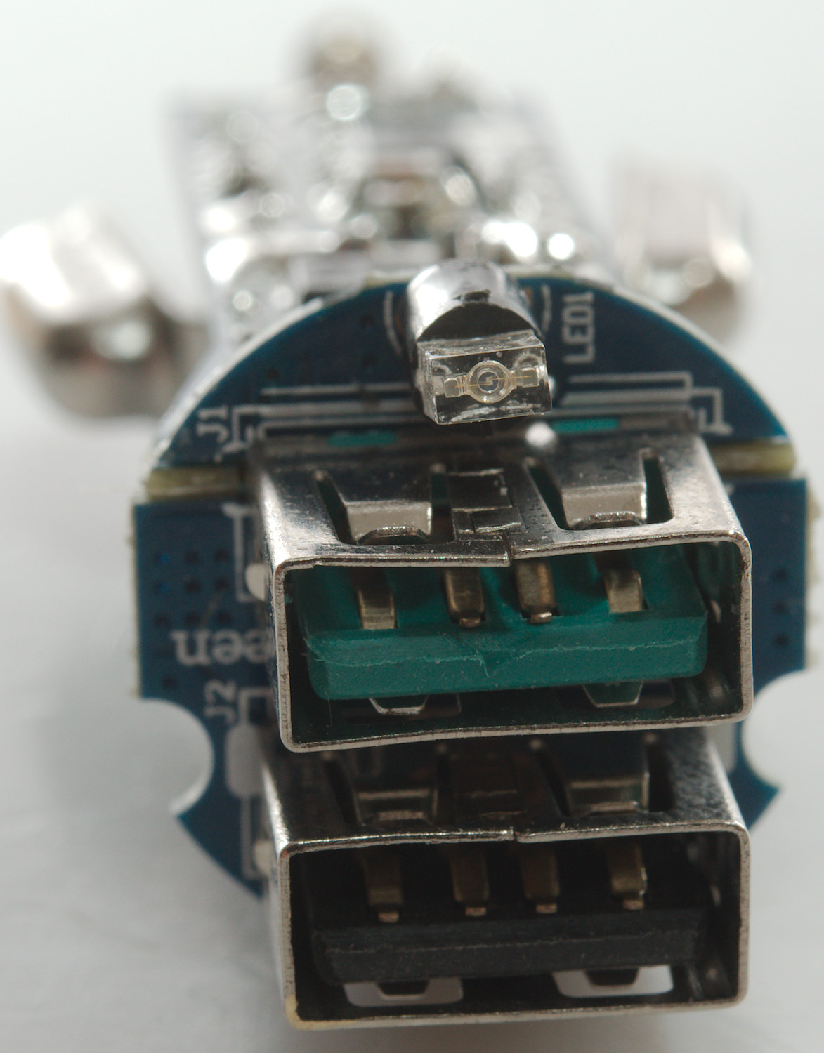
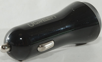
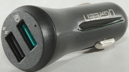
It has two outputs, one standard USB and one QC.
Measurements
- Power consumption when idle is 17mA from 12V and 17mA from 24V
- Normal USB output is coded as Apple 2.4A and DCP
- QC USB output is coded as Apple 2.4A, Samsung, DCP, QC3, Samsung-AFC and Huwai-FCP
- There is blue led on the front behind a small hole.
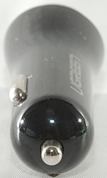
- Weight: 25.0g
- Length: 71.3mm
- Diameter: 27.8mm
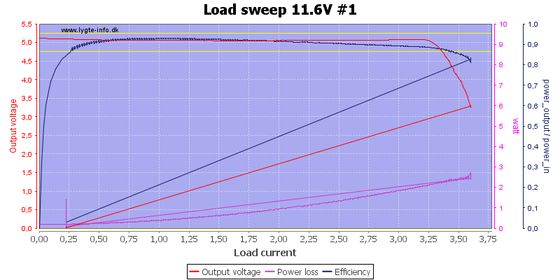
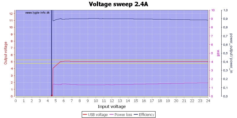
On the 2.4A output voltage starts dropping at around 3.2A and current limit kicks in at 3.6A
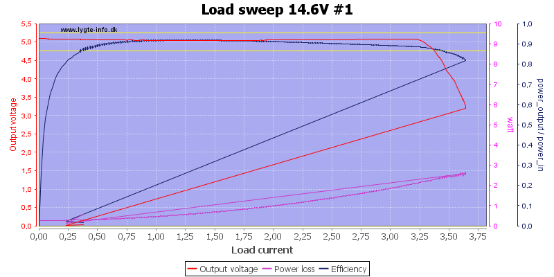
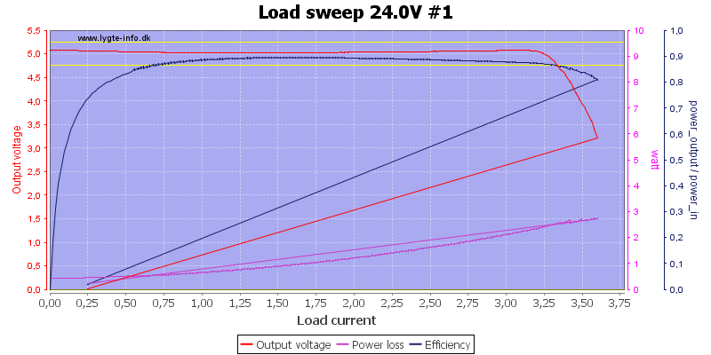
This is the same at any input voltage, but the efficiency goes slightly down at higher input voltage (It is still good efficiency).
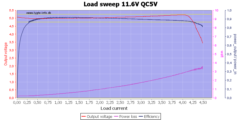
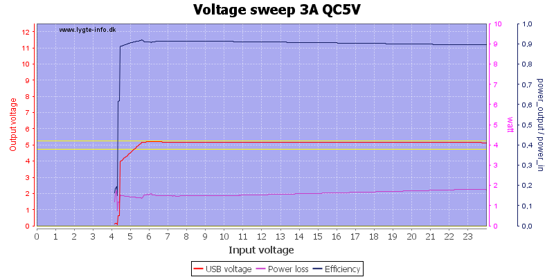
QC is rated for 3A, but can deliver more than 4A before voltage drops or it starts limiting the current. It has some cable compensation.
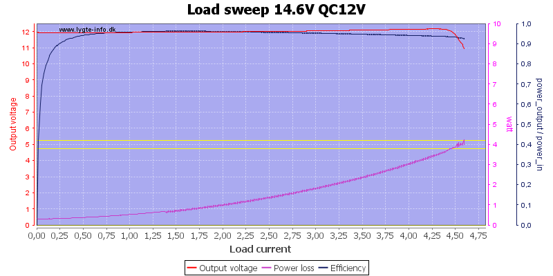
With a fully charged car battery the 12V QC output is 12V and can deliver more than 4A (Rating 1.5A).
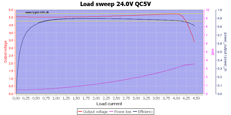
With 5V QC there is no difference between 12V or 24V input.
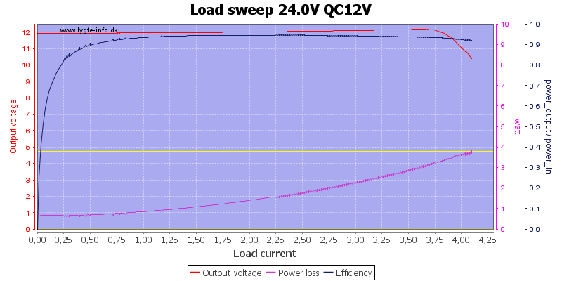
The current limit drops slightly with 24V input on the 12V QC.
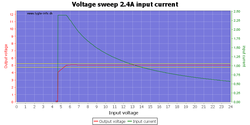
The normal USB output works down to 6V input.
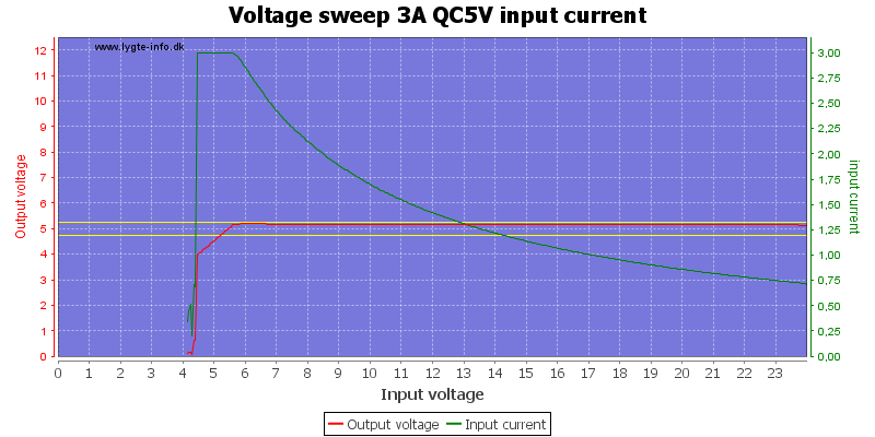
5V QC also works down to 6V input.
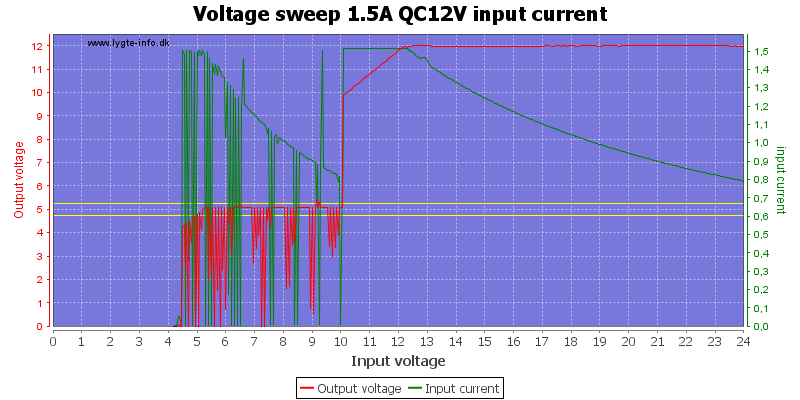
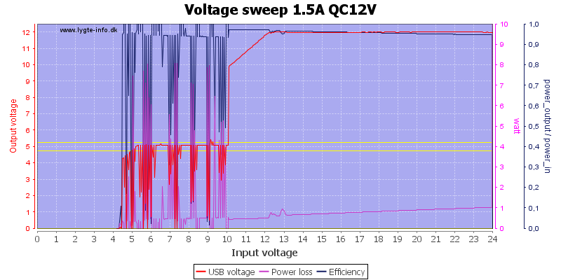
QC at 12V only needs slightly above 12V input to deliver 12V output (very nice) and drops out of QC at 10V input..
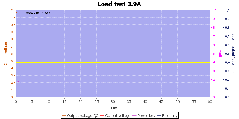
The load test is done with 2.4A draw from normal USB and 12V 1.5A draw from QC USB, it worked fine for 1 hour.
The temperature photos below are taken between 30 minutes and 60 minutes into the one hour test.
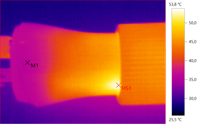
M1: 35.9°C, HS1: 53.8°C
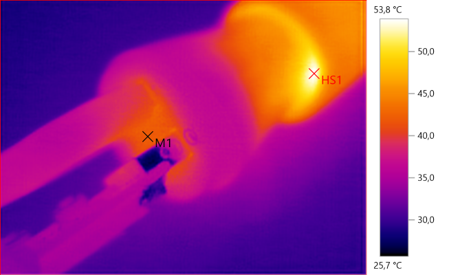
M1: 42.0°C, HS1: 53.8°C
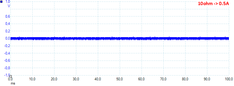
Noise at 0.5A output is 26mV rms and 118mVpp
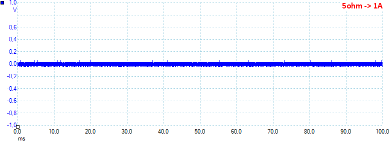
Noise at 1A output is 27mV rms and 119mVpp
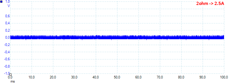
Noise at 2.5A output is 34mV rms and 139mVpp
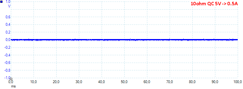
Noise at 0.5A output is 12mV rms and 88mVpp
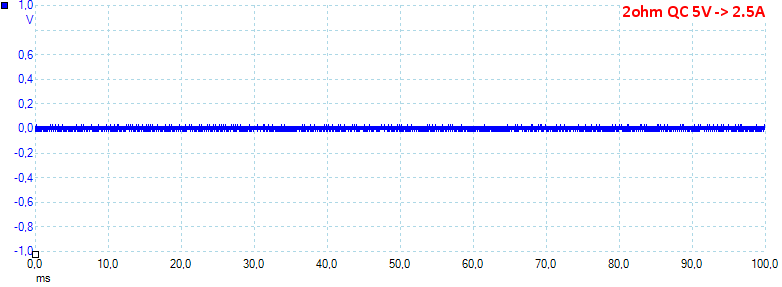
Noise at 2.5A output is 16mV rms and 90mVpp
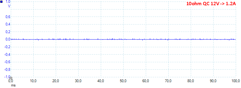
Noise at 1.2A output is 2mV rms and 58mVpp, generally very low noise on bot standard USB and QC USB.
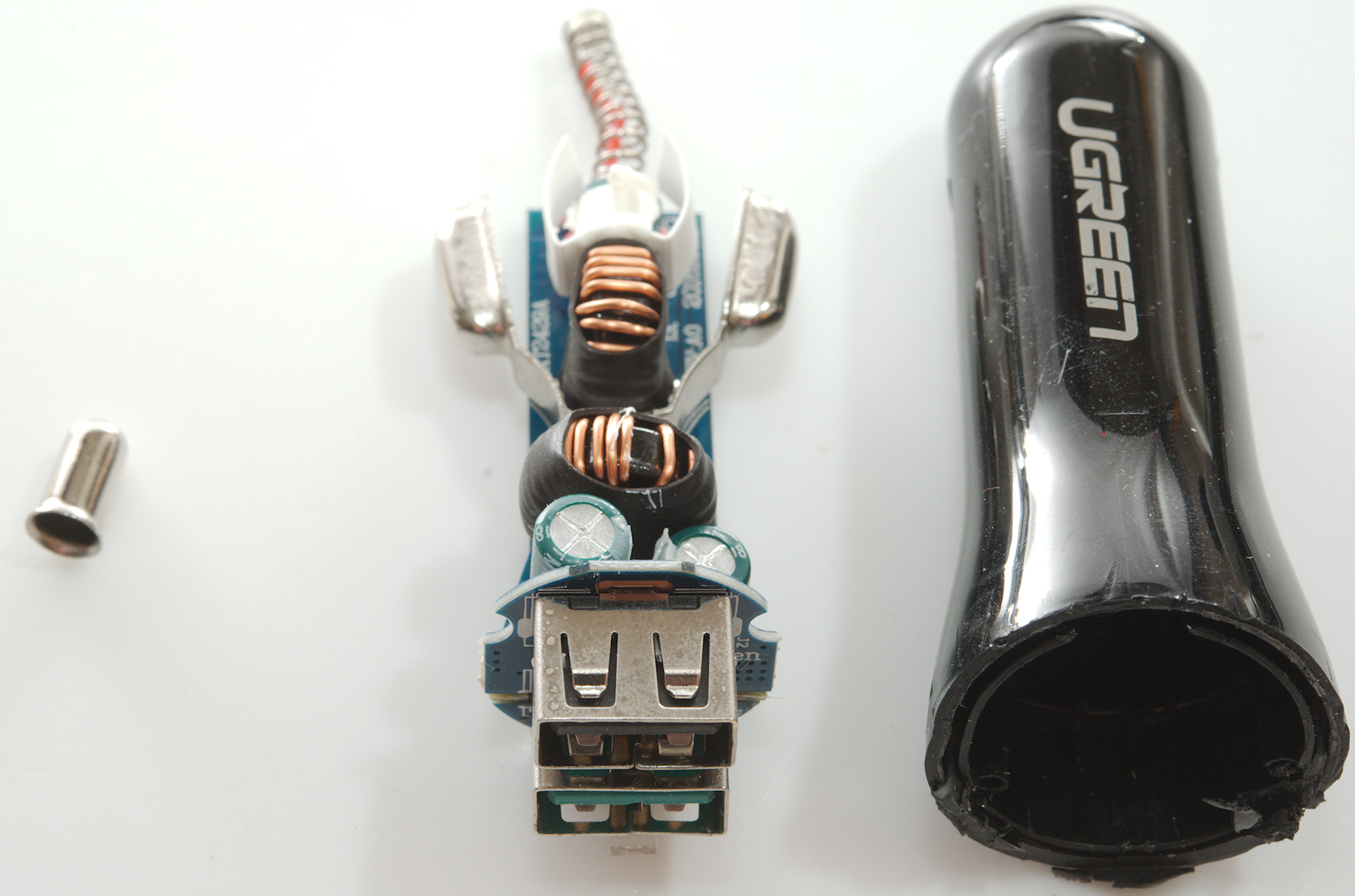
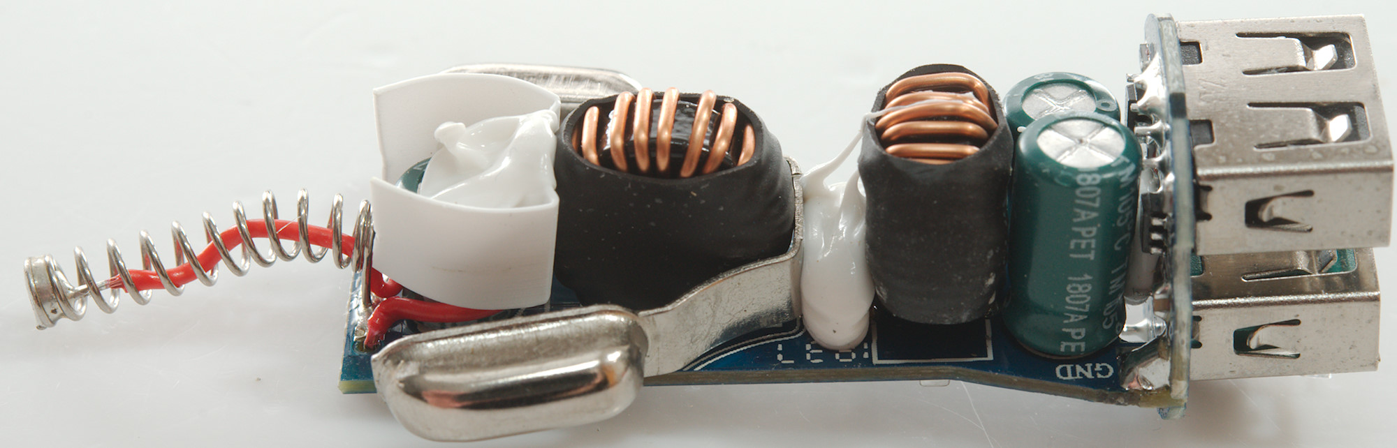
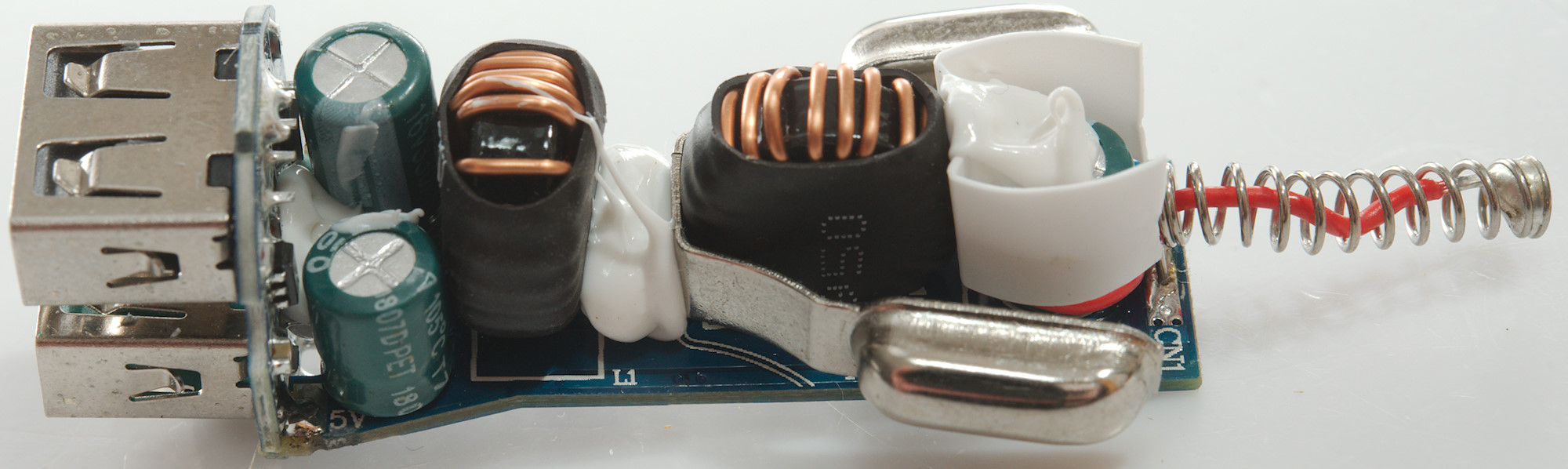
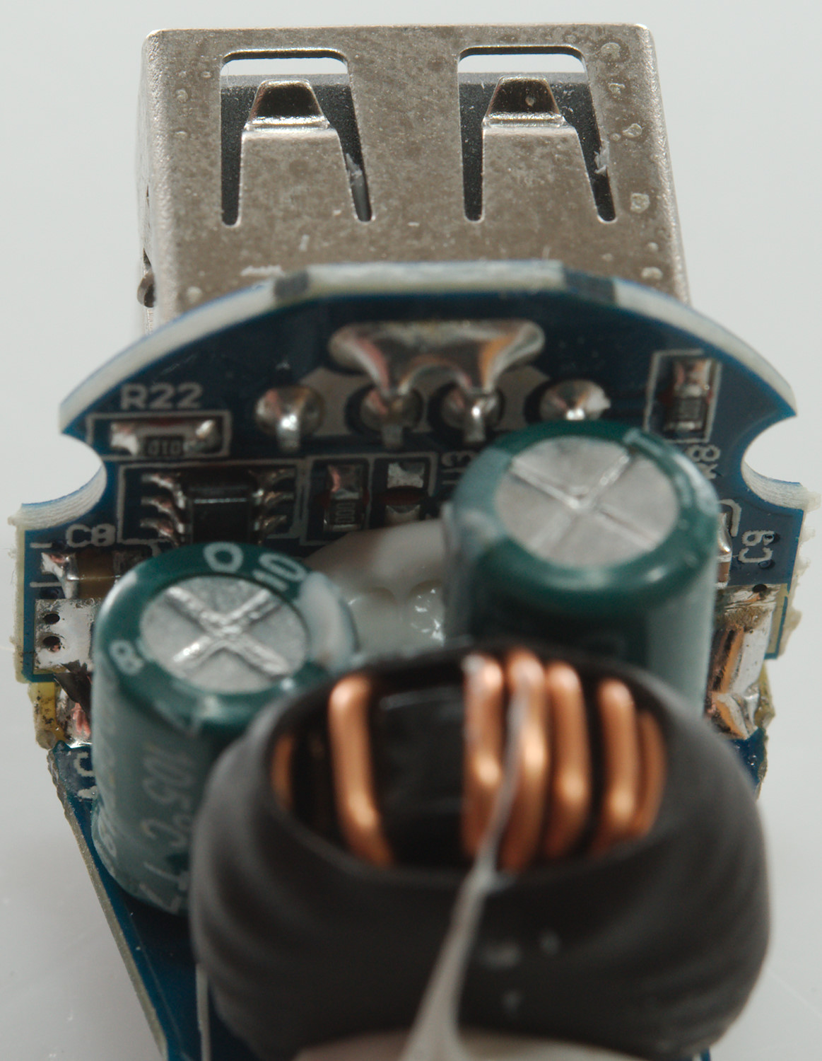
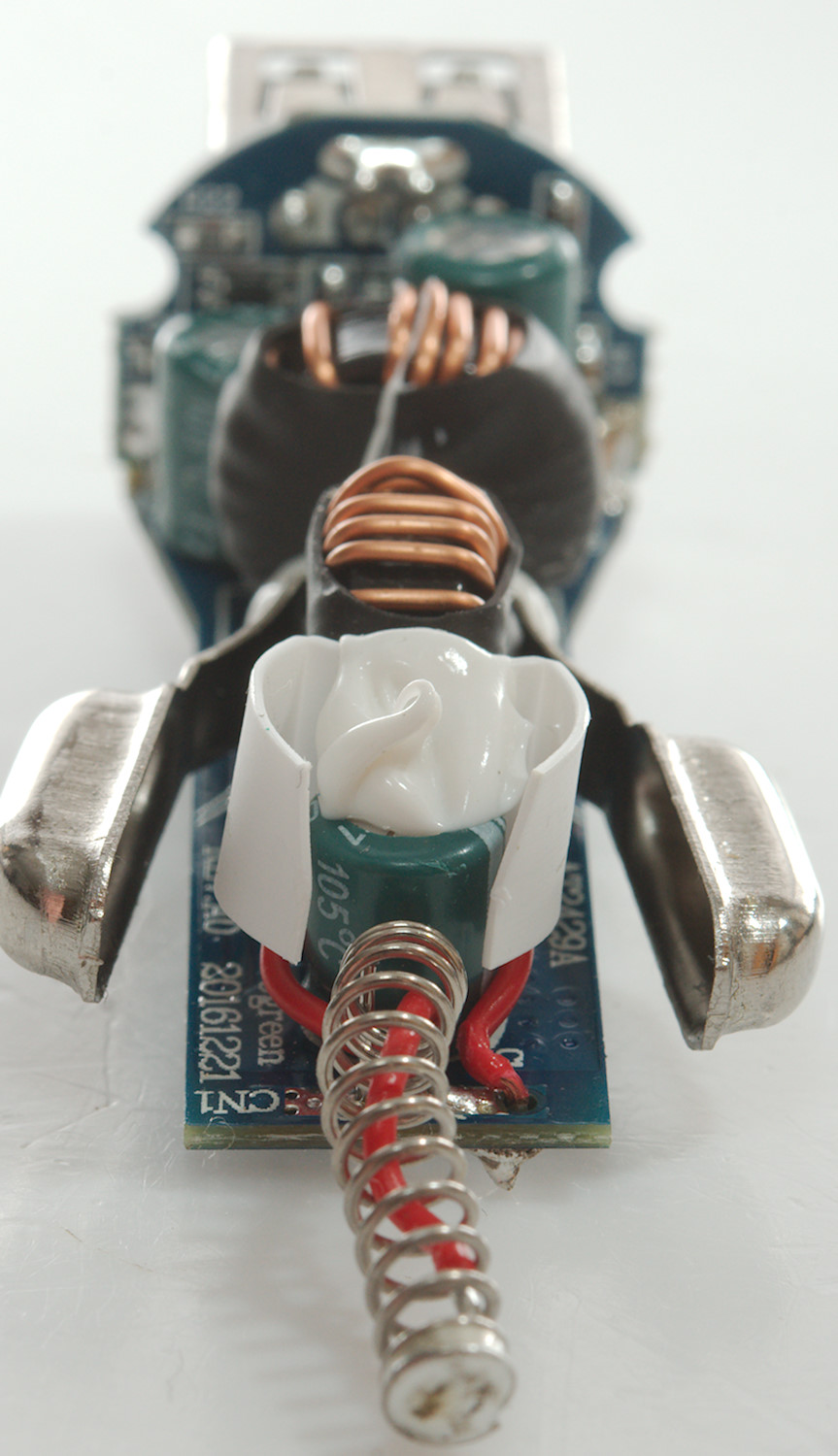
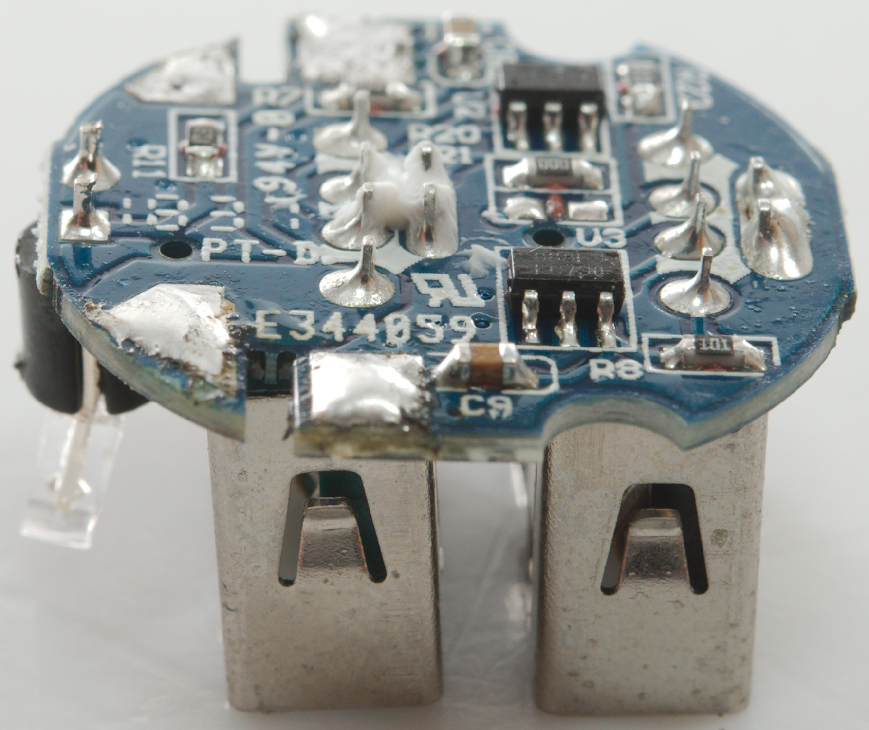
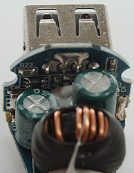
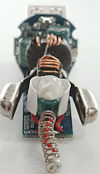
Tear down
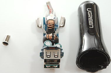
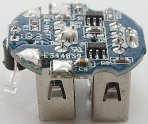
I could not open it up and had to cut. When the front was removed I could push the circuit board out (With some difficulties).
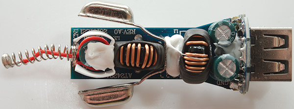
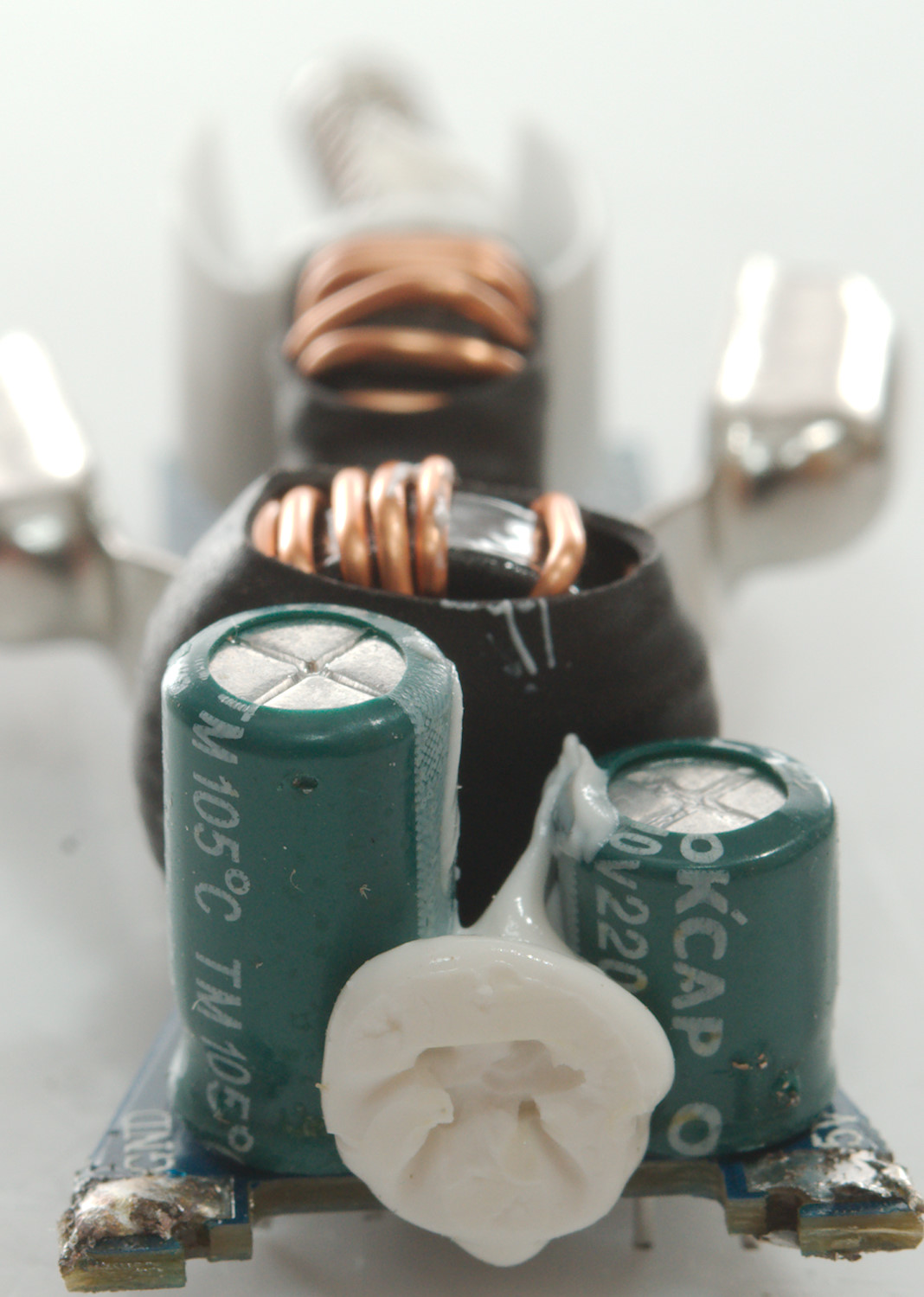
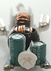
On this side is a input capacitor, two inductors (L1 & L3) for standard USB and QC and two output capacitors. The input spring has a wire inside to increase current capabilities.
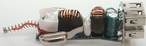
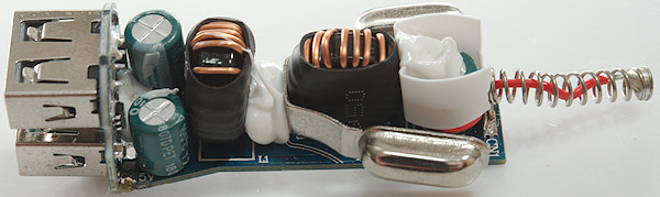

I wonder if the green part is a fuse, resistor or inductor, R & L letters indicate either resistor or inductor, but it looks like it might be a fuse.
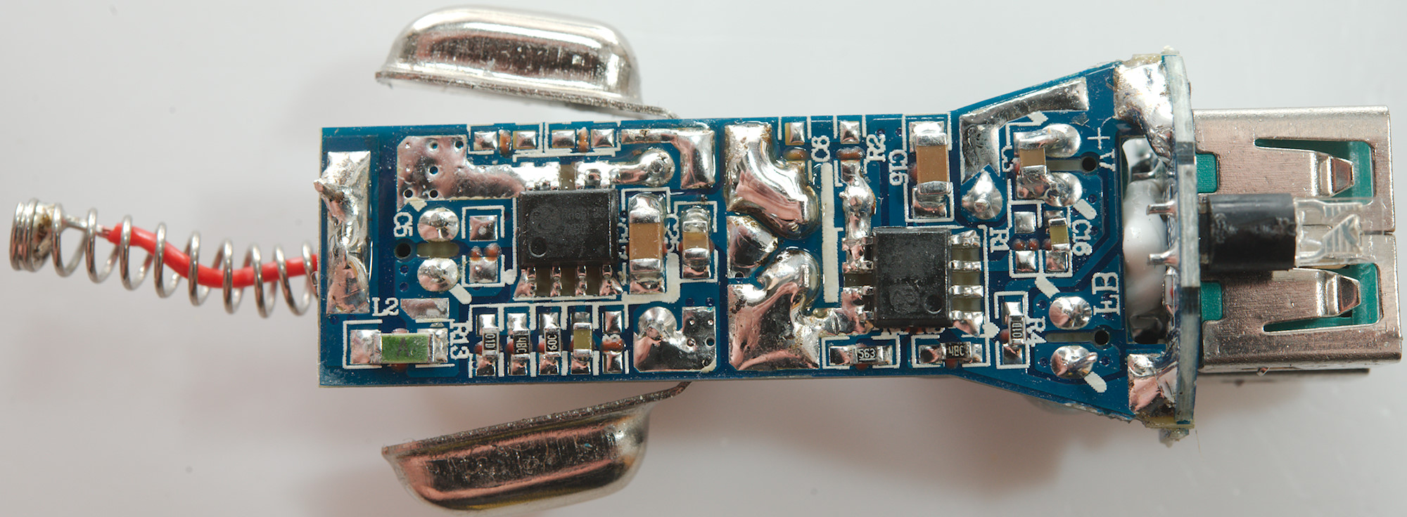
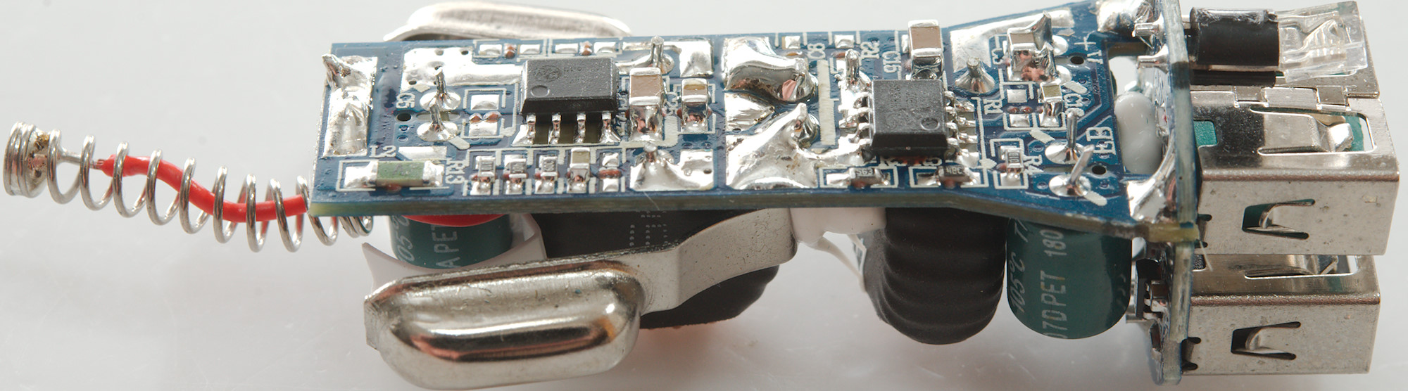
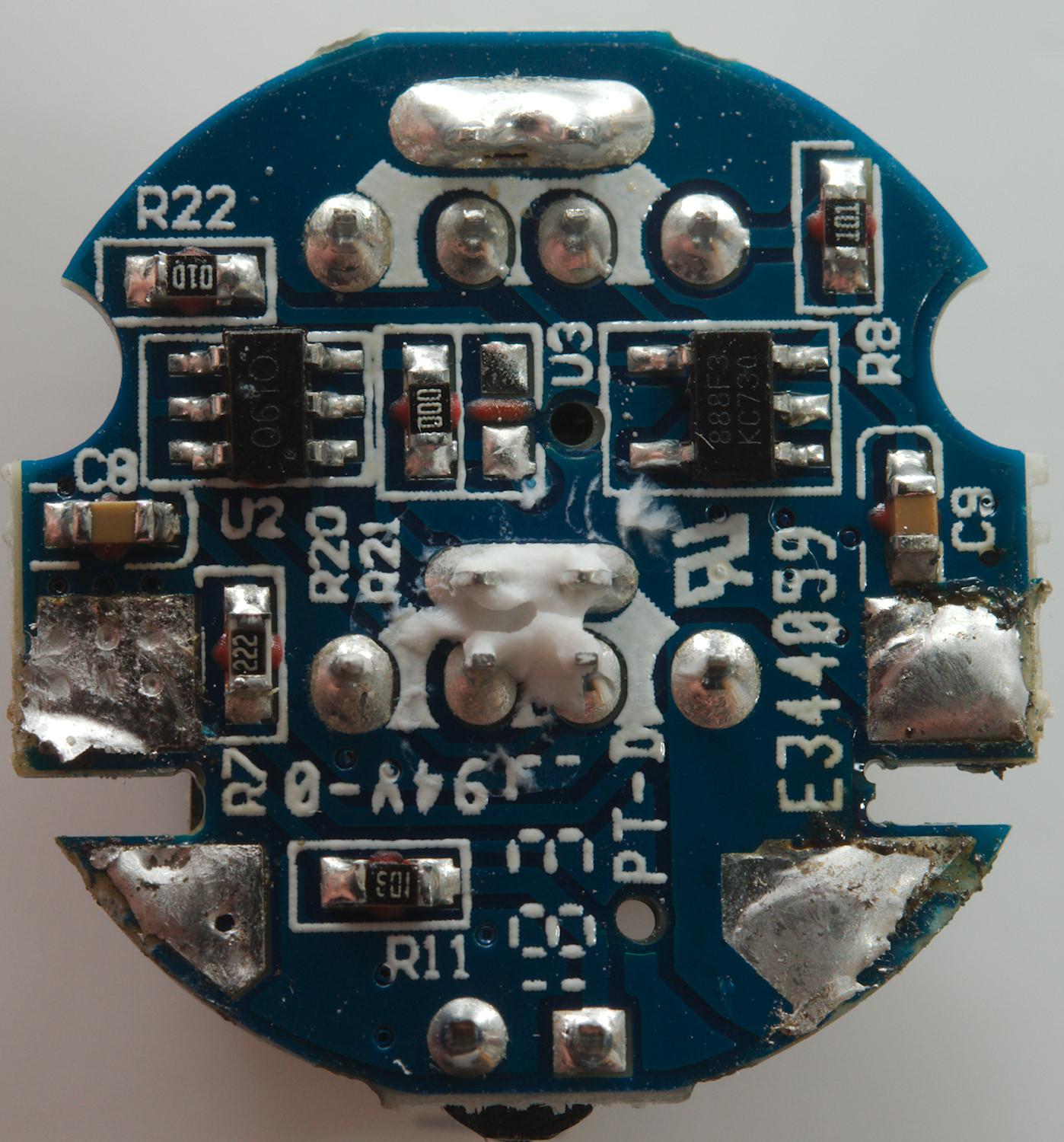
There is two switcher IC's (RH8603S), each can handle 32V input and 3A output.


There is some chips on the front, that must be the QC and the standard USB charge optimizer chips.
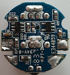
The 5 pin chip (U3: Marked KC730) is for standard USB and the 6 pin chp (U2: Marked Q610) is for QC.
The four connections to the switcher PCB must be: 0V, 5V, QC, QC-control.
Being a 12V device there is no need to test with high voltages.
Conclusion
This is a fairly good USB car charger, one output can basically do everything, the other is a more standard USB output with high current and auto coding.
Notes
Read more about how I test USB power supplies/charger
Compare car chargers and other DC supplied chargers