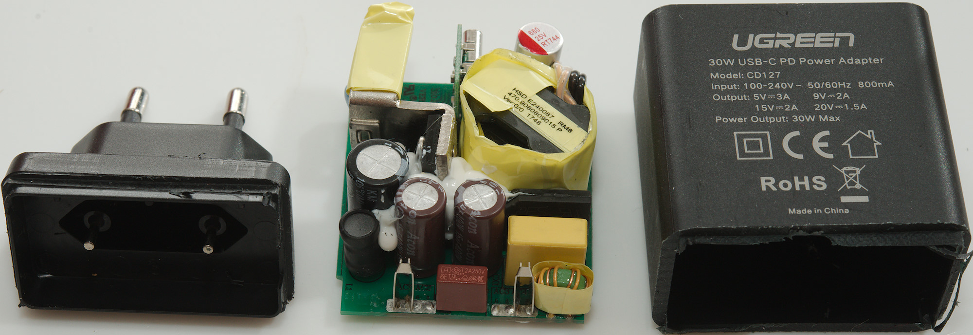
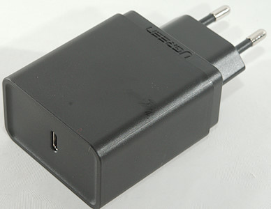
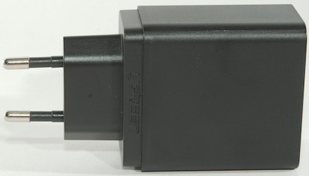
UGreen USB-C PD 30W CD127
Official specifications:
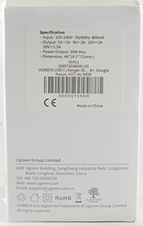
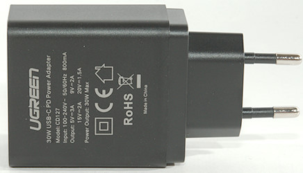
- Brand: Ugreen
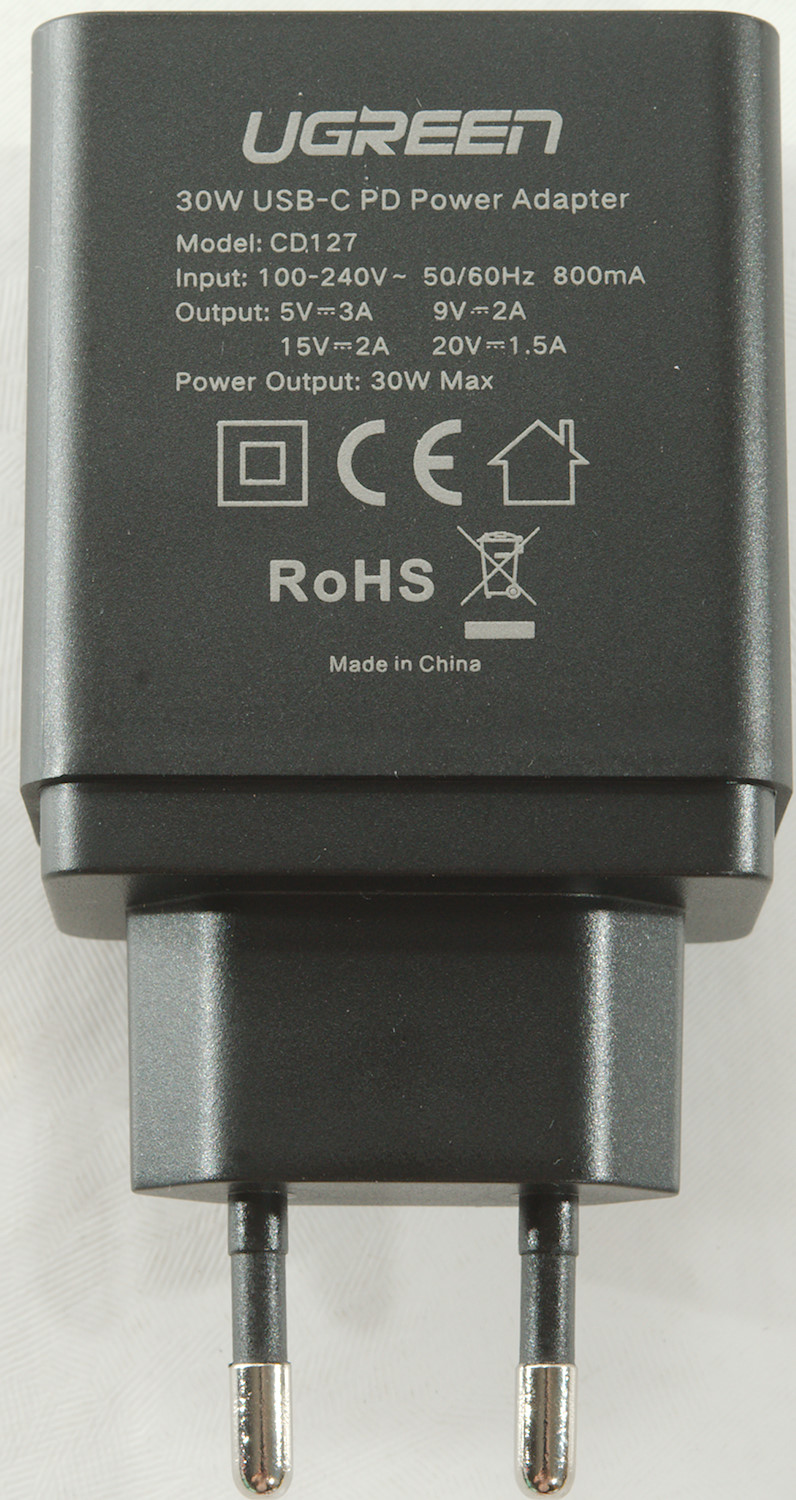
- Model No: CD127
- Certfication: CCC certified
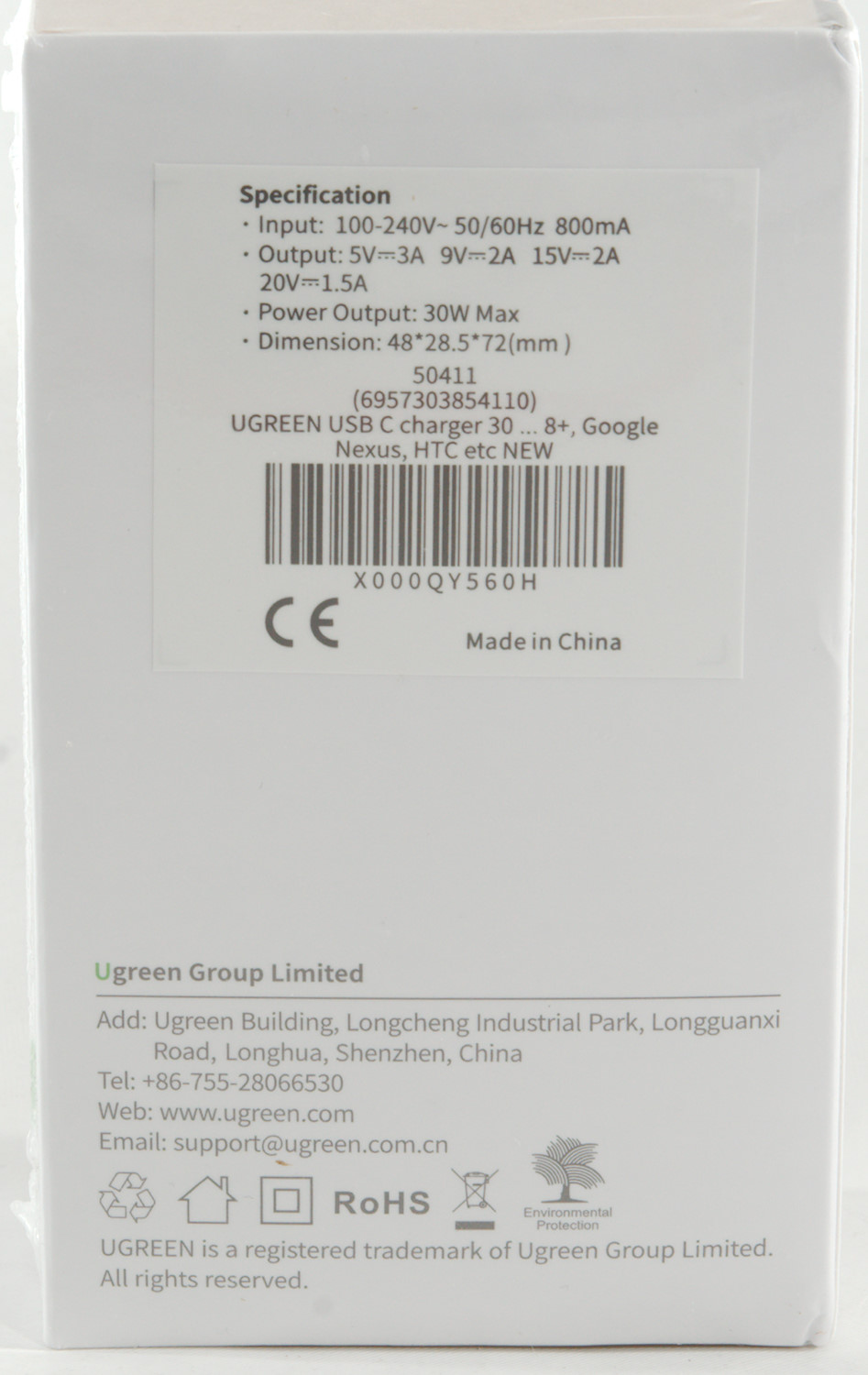
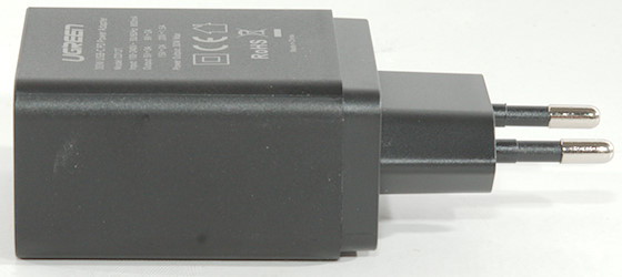
- Input: 100-240 V AC 50/60 Hz 800 mA
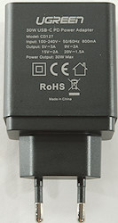
- Output: 5V 3A, 9V 2A, 15V 2A, 20V 1.5A
- Supports Output: 30 W max
- Shell: PC Fireproof
- Color: Black
I got it from aliexpress dealer: Ugreen Official Store
The charger was in a white cardboard box
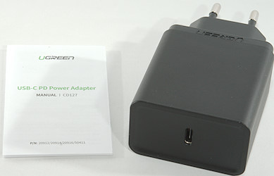
And included a instruction sheet.
Measurements
- PD voltages: 5V 3A, 9V 3A, 12V 2.5A, 15V 2A, 20V 1.5A
- Usb output has DCP and QC3 coding in addition to PD
- Power consumption when idle is 0.08 watt
- Weight: 92.3g
- Size: 93 x 48.4 x 29mm
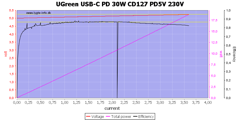
The charger is rated for 3A and can deliver slightly above 3.5A on 5V, this is fine. There is cable compensation.
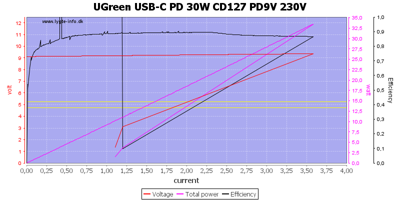
At 9V the current is also about 3.5A
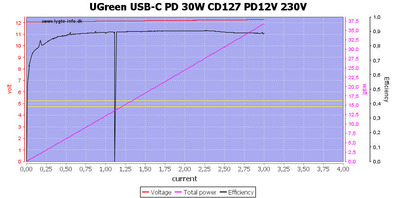
At 12V the current is dropped to 3A and rating is 2.5A
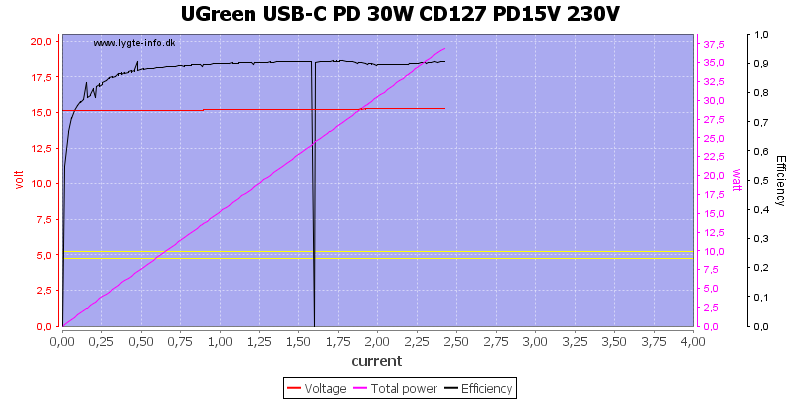
At 15V the current is about 2.3A.
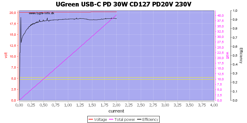
And at 20V it is about 2A
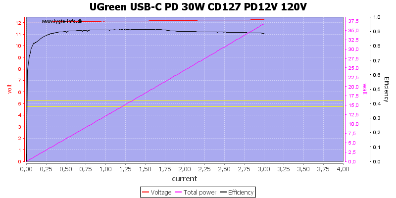
A test at 120VAC did not show any differences.
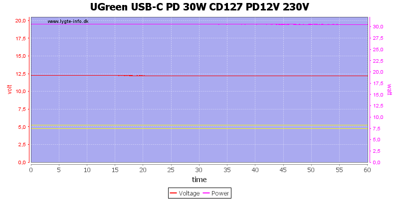
Running 1 hour at 12V 2.5A worked fine.
The temperature photos below are taken between 30 minutes and 60 minutes into the one hour test.
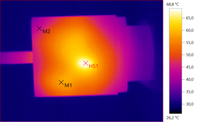
M1: 57.6°C, M2: 44.0°C, HS1: 68.8°C
HS1 must be the switcher transistor
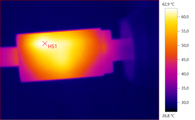
HS1: 62.9°C
HS1 is the heatsink for the switcher transistor.
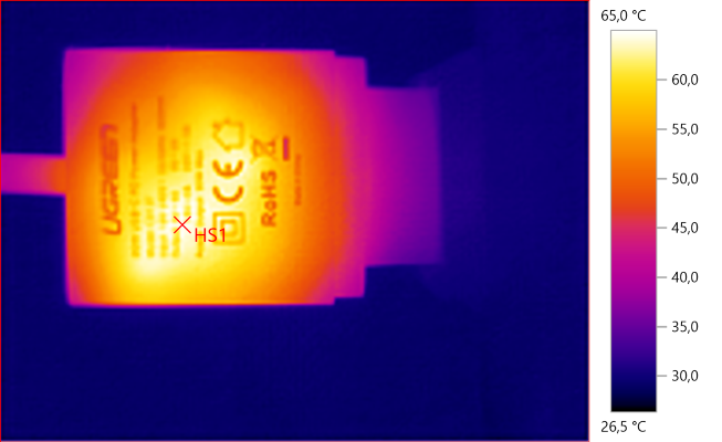
HS1: 65.0°C
Here HS1 is the transformer.
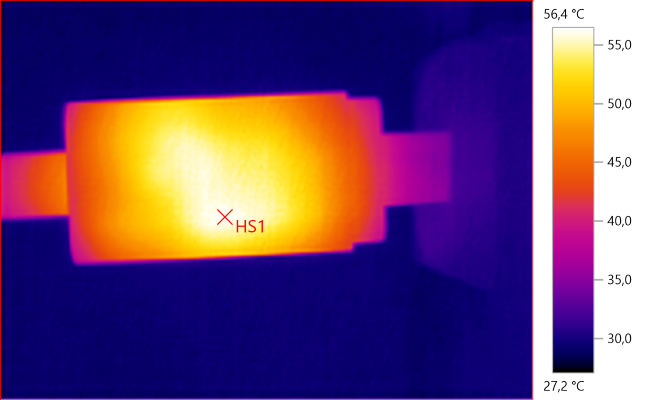
HS1: 56.4°C
And again HS1 is the transformer
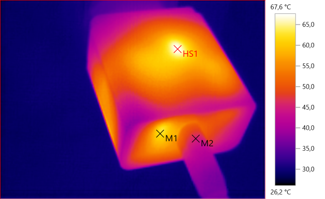
M1: 62.2°C, M2: 45.4°C, HS1: 67.6°C
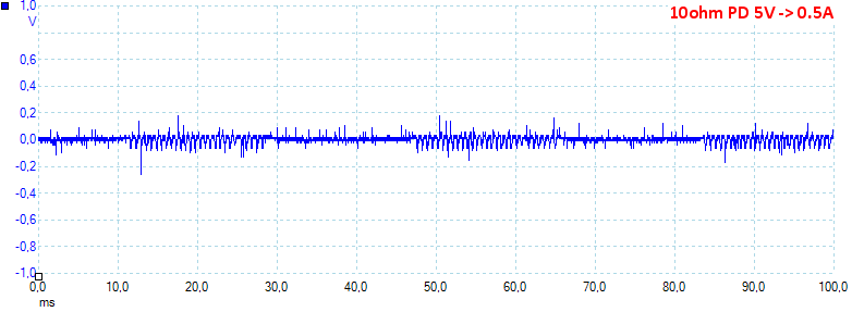
At 5V 0.5A the noise is 29mV rms and 498mVpp
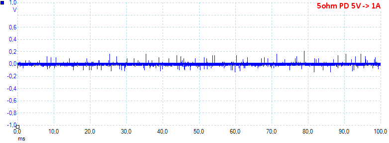
At 5V 1A the noise is 29mV rms and 467mVpp.
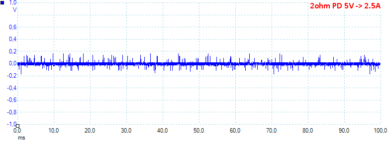
At 5V 2.5A the noise is 77mV rms and 437mVpp.
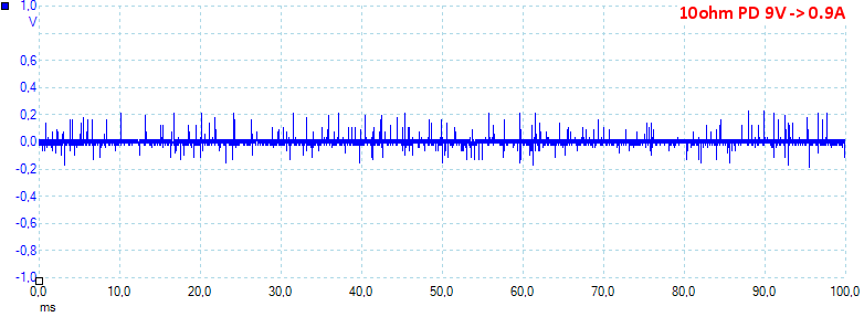
At 9V 0.9A the noise is 36mV rms and 644mVpp.
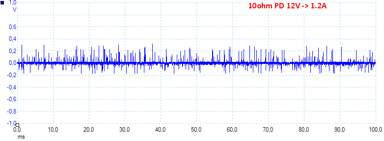
At 12V 1.2A the noise is 39mV rms and 626mVpp.
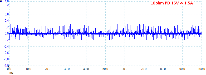
At 15V 1.5A the noise is 45mV rms and 640mVpp.
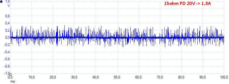
At 20V 1.3A the noise is 48mV rms and 684mVpp.
Tear down
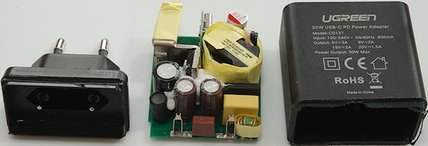
The charger was glued together very well and I had to cut it open.

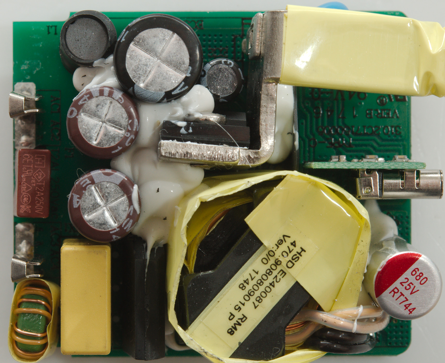
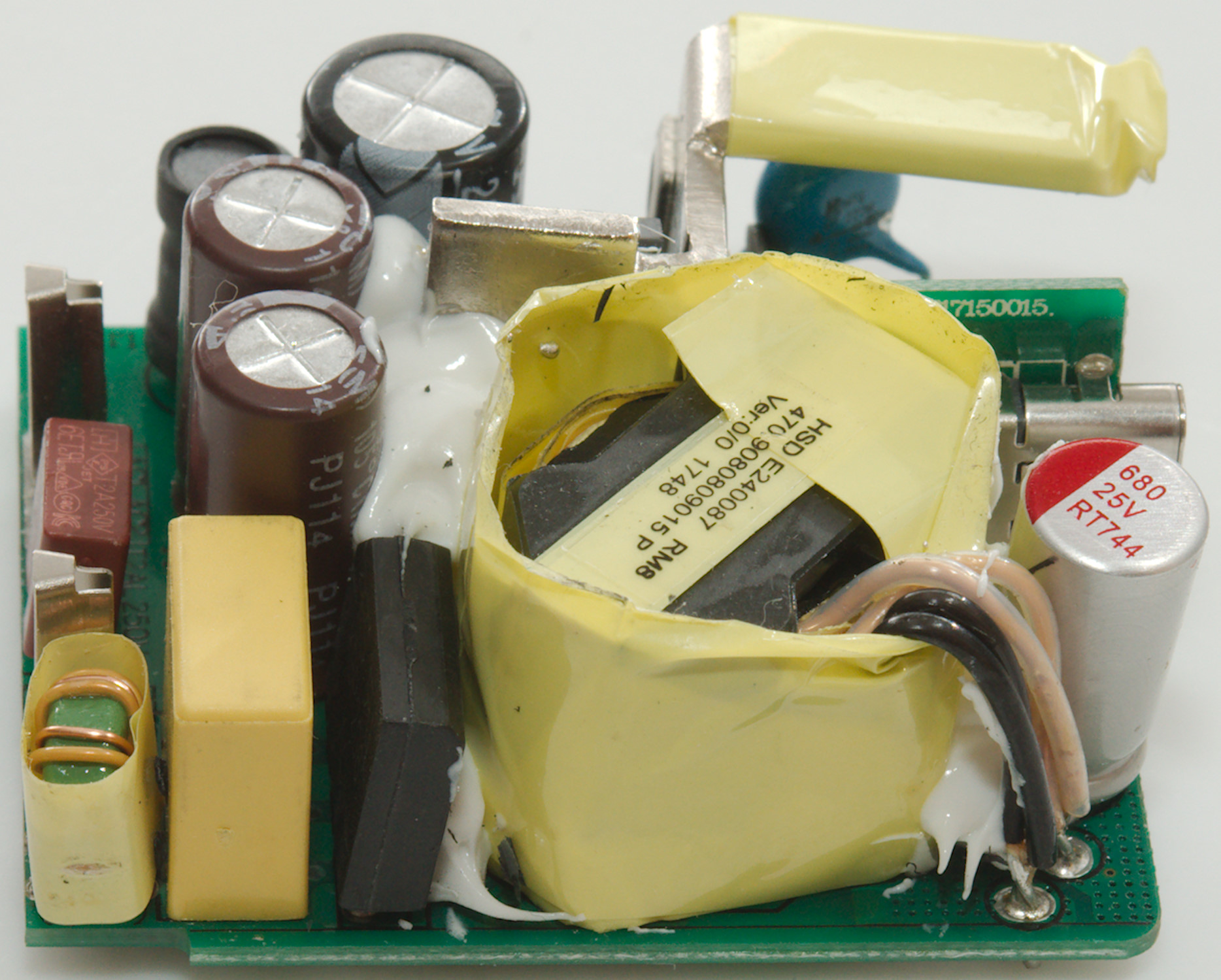
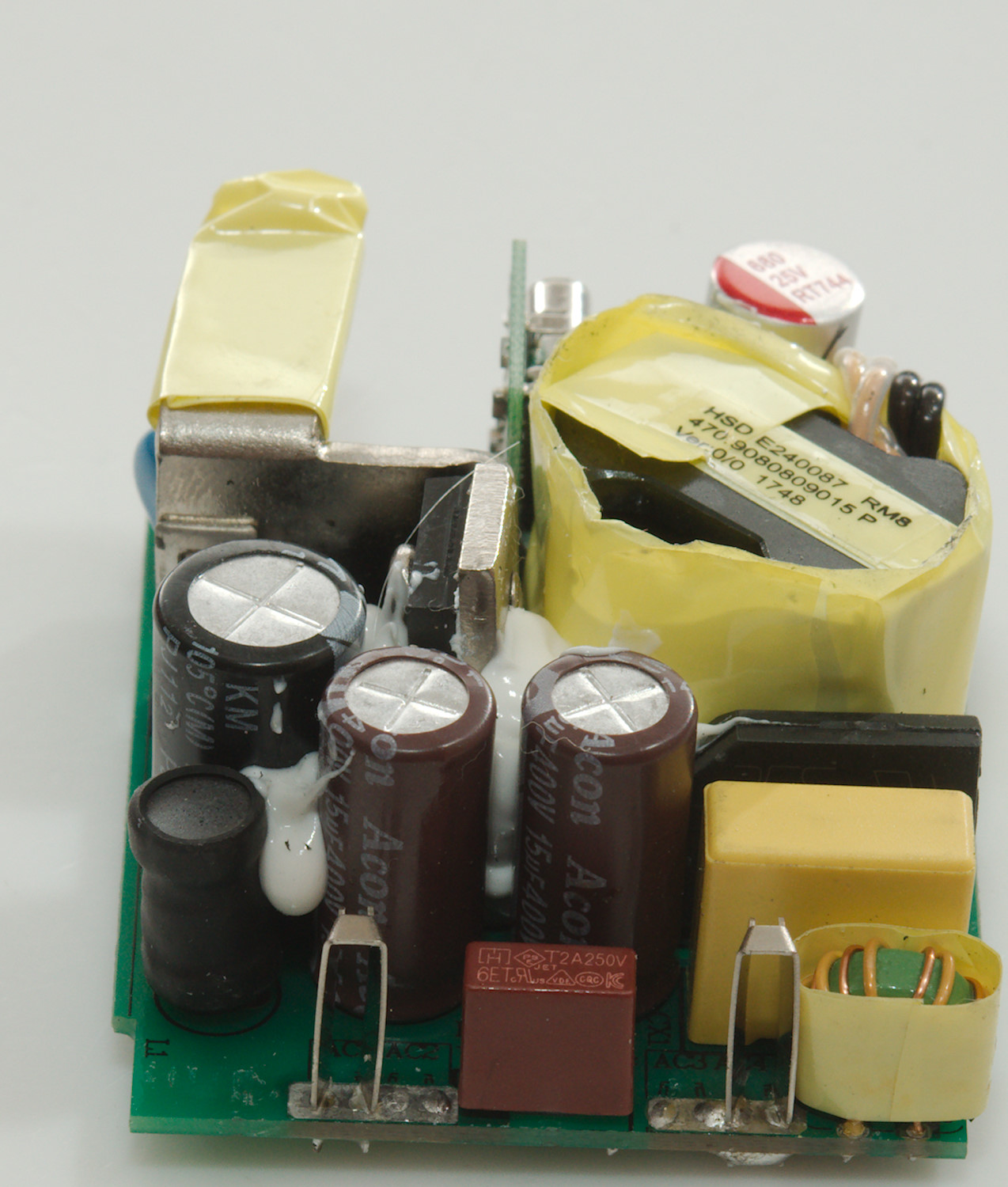
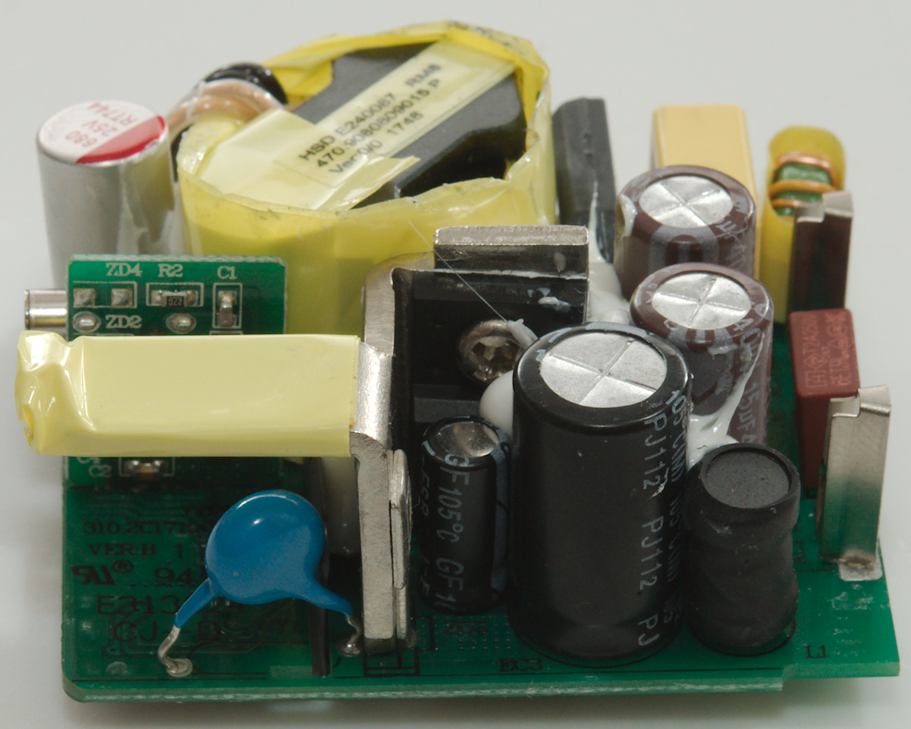
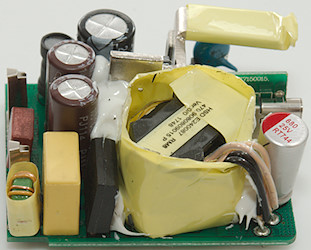
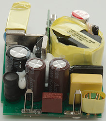
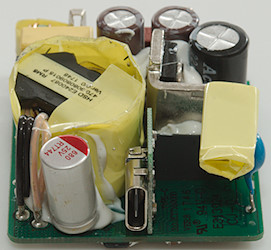
At the input is a fuse and a common mode coil, the bridge rectifier is on this side next to the transformer. There is a inductor (L1) between two of the smoothing capacitors. The switcher transistor is mounted on a small heatsink.
The transformer has two parallel secondary windings going out at the top and down to the circuit board, this secures good isolation to mains.
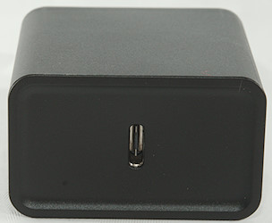
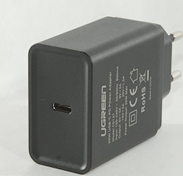
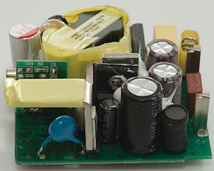
The USB-C connector is on a raiser board. Being PD with up to 20V output the output capacitor is rated for 25V.
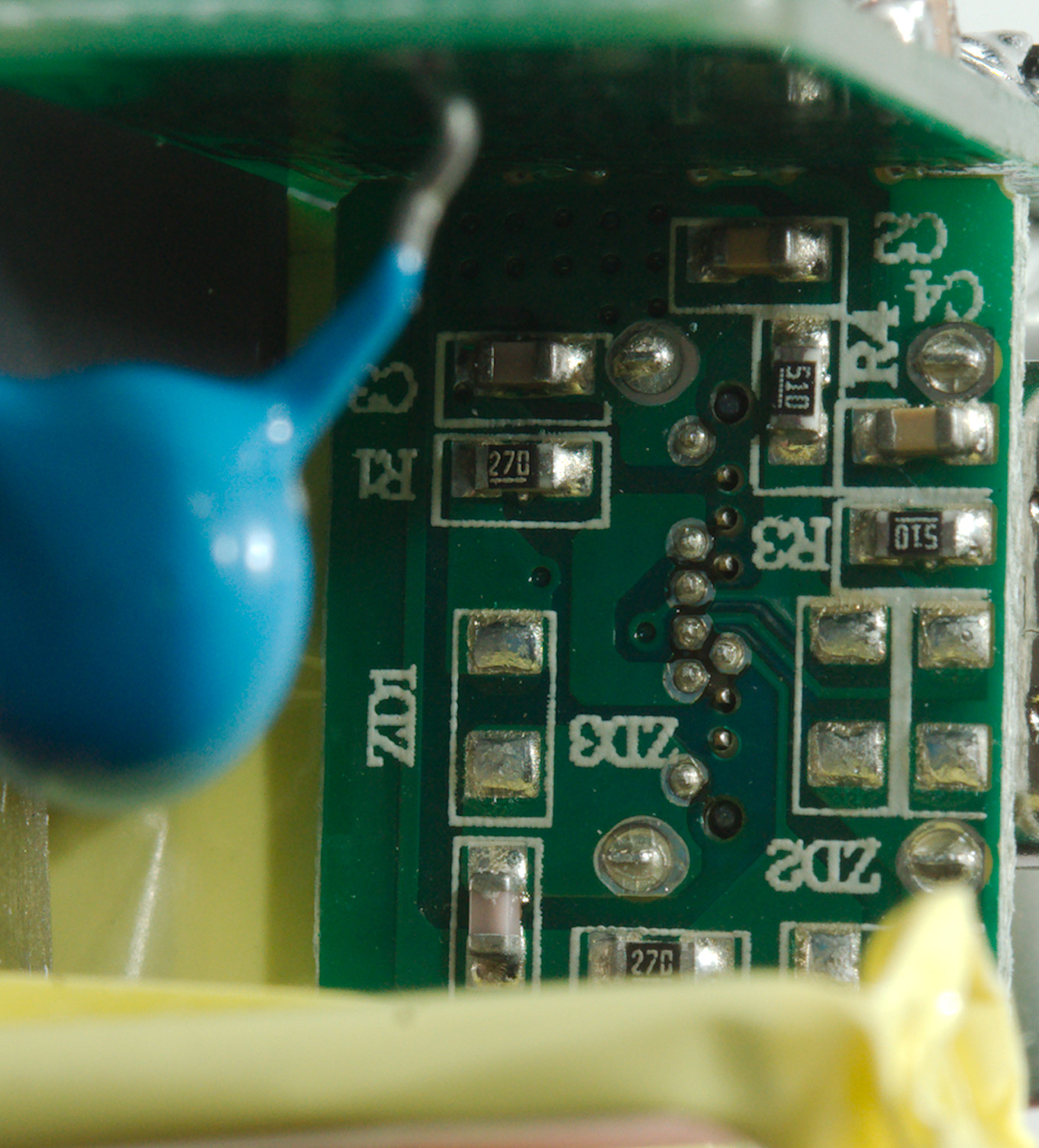
The raiser board has a couple of passive components on it. It is connected to power lines, the old usb data lines (For QC support) and the CC line (For PD support).

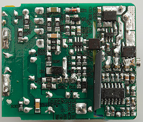
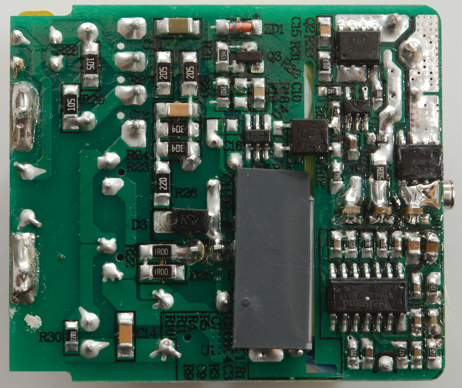
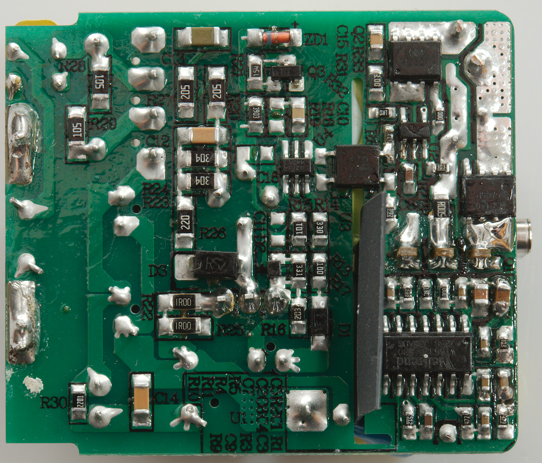
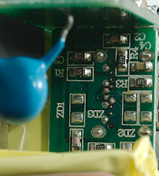
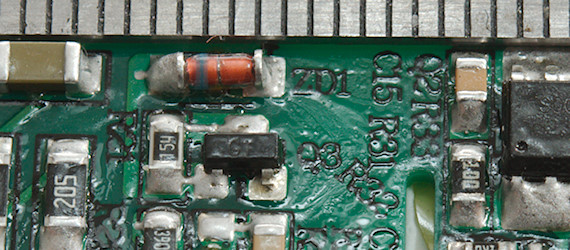
All the active parts are on this side. The mains switcher controller (U4) next to the opto-coupler (U3). On the other side of the slot is a synchronous rectifier (U2) controller and a power transistor (Q2). To switch the PD voltage on/off is another power transistor (Q1) and then there is the PD controller chip (WT6632F).
With both a slot and a isolation sheet, it is only at the edge the distance can be critical and it is good enough.
The charger passed the 2830 volt and 4242 volt test, this means it is it is fairly safe.
Conclusion
The charger supports voltage from 5V to 20V with 3A and 30W output power and it can deliver rated power, this is a nice range for a PD supply. I did not see any safety problems, but the noise is a bit on the high side.
I will call it a good supply.
Notes
Index of all tested USB power supplies/chargers
Read more about how I test USB power supplies/charger
How does a usb charger work?