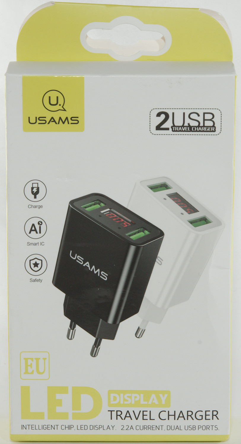
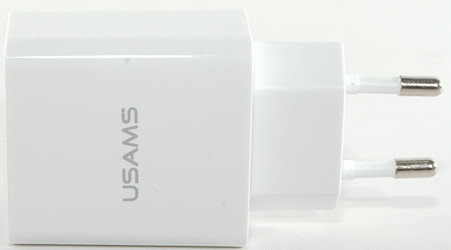
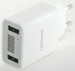
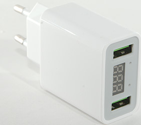
USAMS Led display travel charger
Official specifications:
- Brand: USAMS
- USB Port: 2Ports
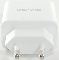
- Plug: EU Plug
- Product Weight: 60g
- Dimensions: 88mm*50mm*23mm
- Color: Black, White
- Total Power: 11W
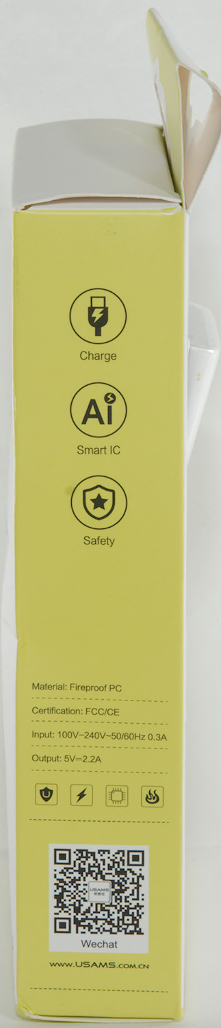
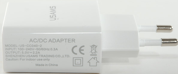
- Input: 100-240V
- Output: 5V/2.2A
- Material: Fireproof PC
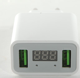
- Feature: LED screen display
- Protection: Insert Smart Circuit, Smart Identification
- Certification: CE FC RoHS
I got it from a Banggood
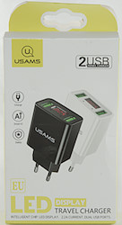
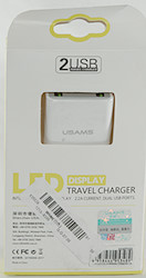
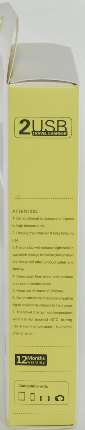
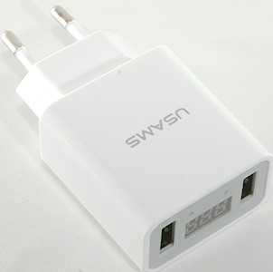
It arrived in a clamshell box with specifications on it.
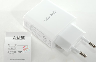
The box contained the charger, no manual or instruction sheet.
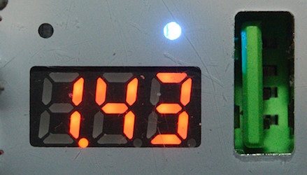
Load current.
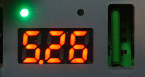
Voltage, measured somewhere inside the circuit.
Measurements
- Both outputs are auto code with DCP, Samsung and Apple2.4A
- Outputs are in parallel.
- Display turns on at 0.22A and turns off at 0.07A
- Voltage is only showed when display turns on, when a load is applied the display will show the voltage twice and then only show current.
- Power consumption when idle is 0.08 watt
- Weight: 48.2g without accessories
- Size: 82 x 42.5 x 24.1mm
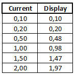
The current readout is fairly precise. It looks like the voltage readout is measuring voltage before the current shunt, i.e. it will show too high voltage when output is loaded.
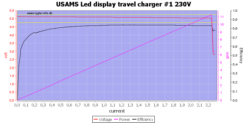
Output can deliver the rated 2.2A
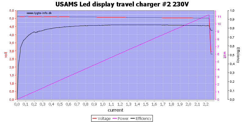
On either port.
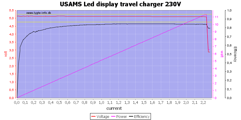
And also for both ports together.
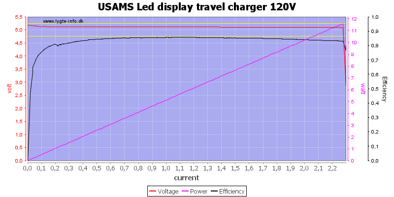
The current is the same at 120VAC
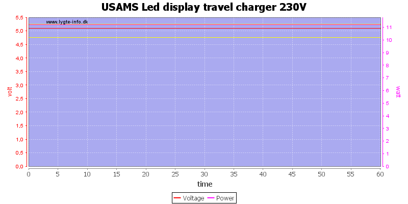
There was no problem running for 1 hour at rated load, i.e. 2.2A.
The temperature photos below are taken between 30 minutes and 60 minutes into the one hour test.
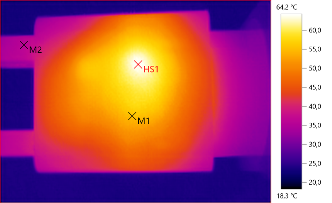
M1: 55.6°C, M2: 36.0°C, HS1: 64.2°C
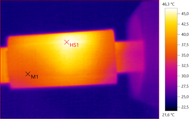
M1: 35.3°C, HS1: 46.3°C
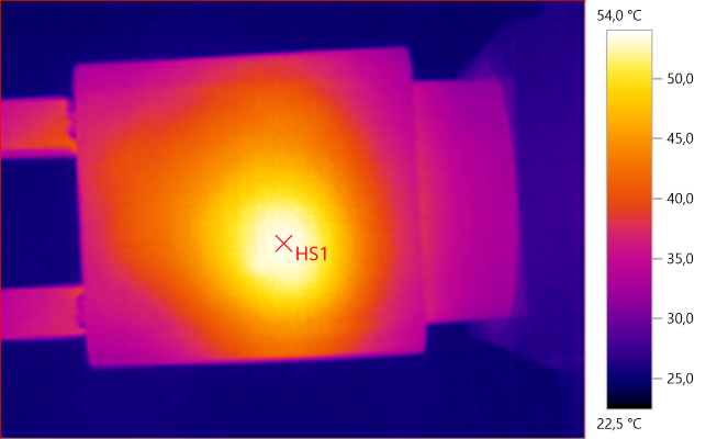
HS1: 54.0°C
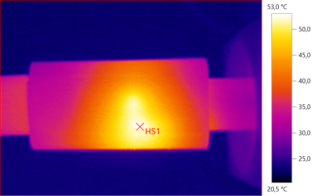
HS1: 53.0°C
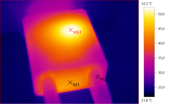
M1: 43.7°C, M2: 34.6°C, HS1: 52.3°C
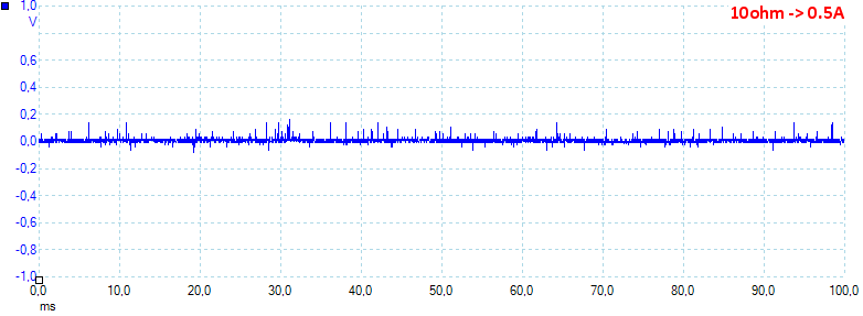
At 0.5A the noise is 14mV rms and 260mVpp
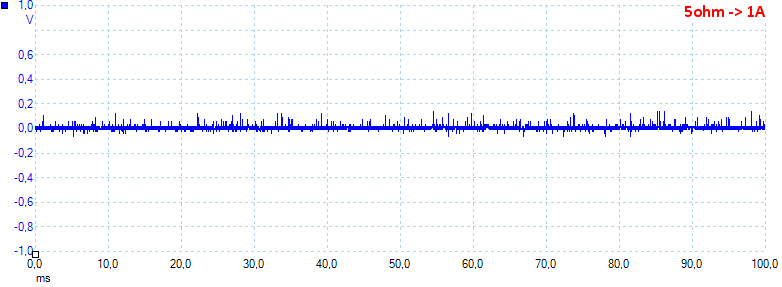
At 1A the noise is 17mV rms and 251mVpp
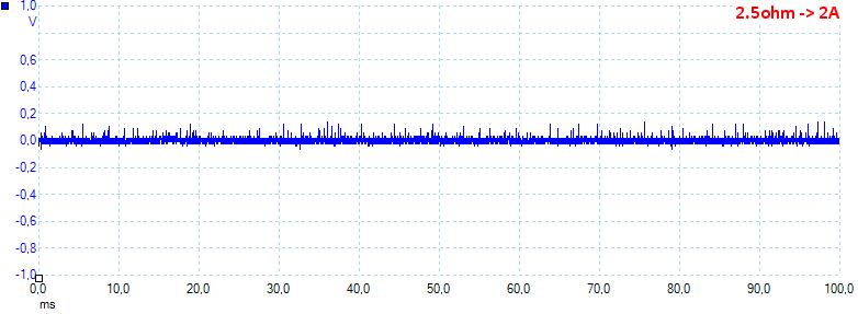
At 2A the noise is 22mV rms and 229mVpp.
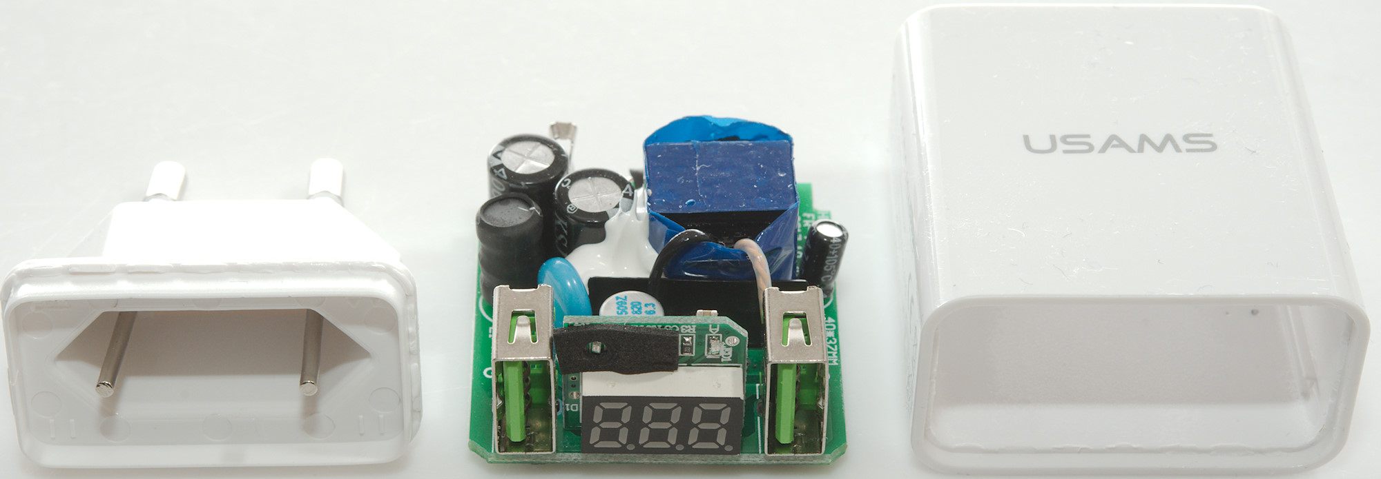
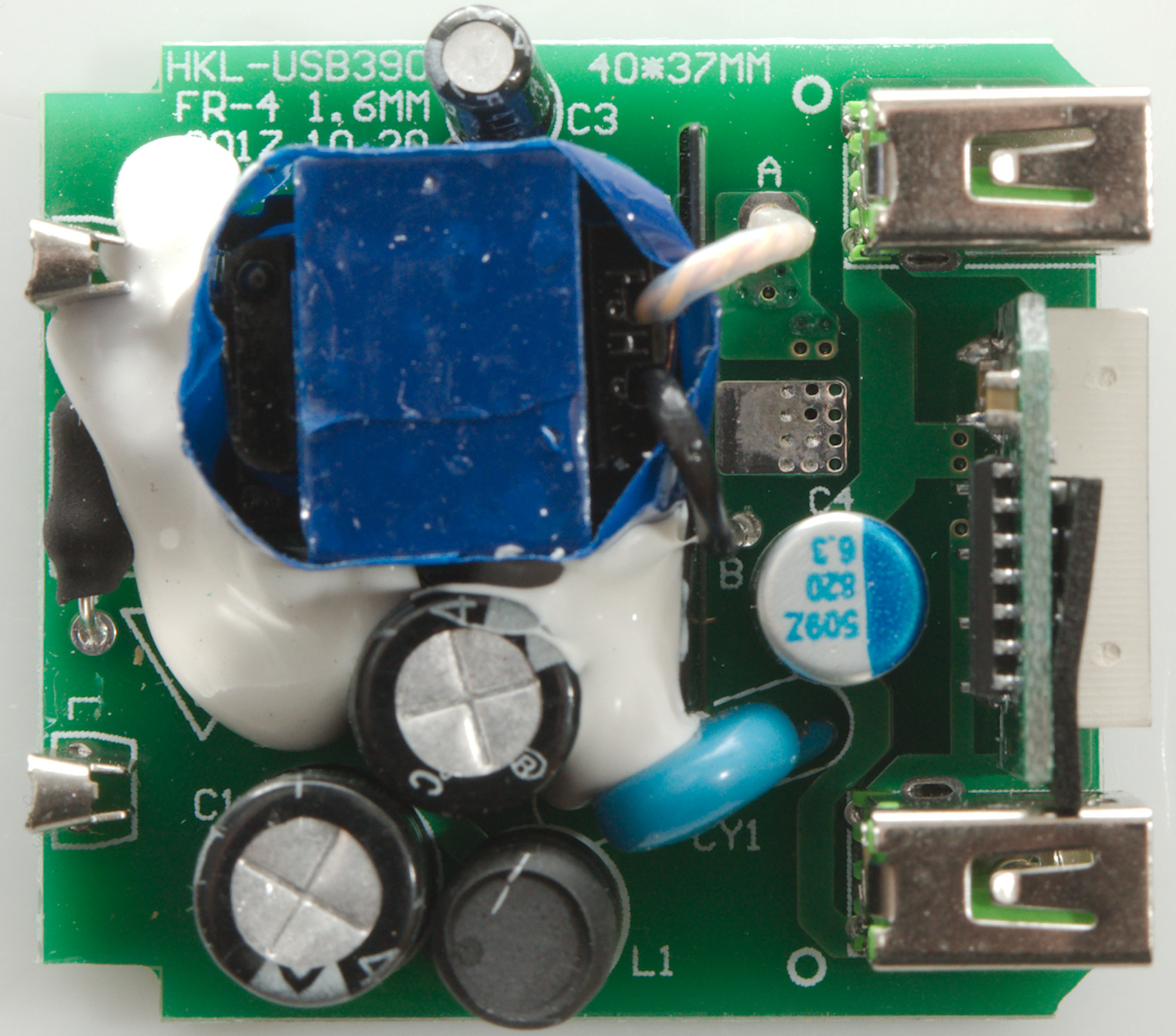
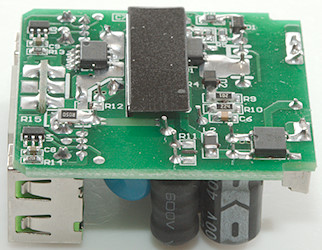
Tear down
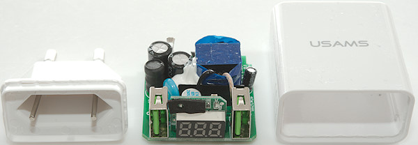
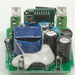
A bit pressure with my vice and I could remove the bottom of this charger.
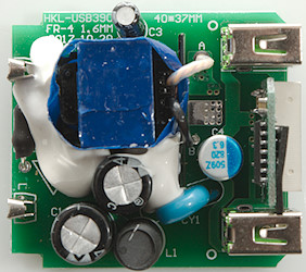
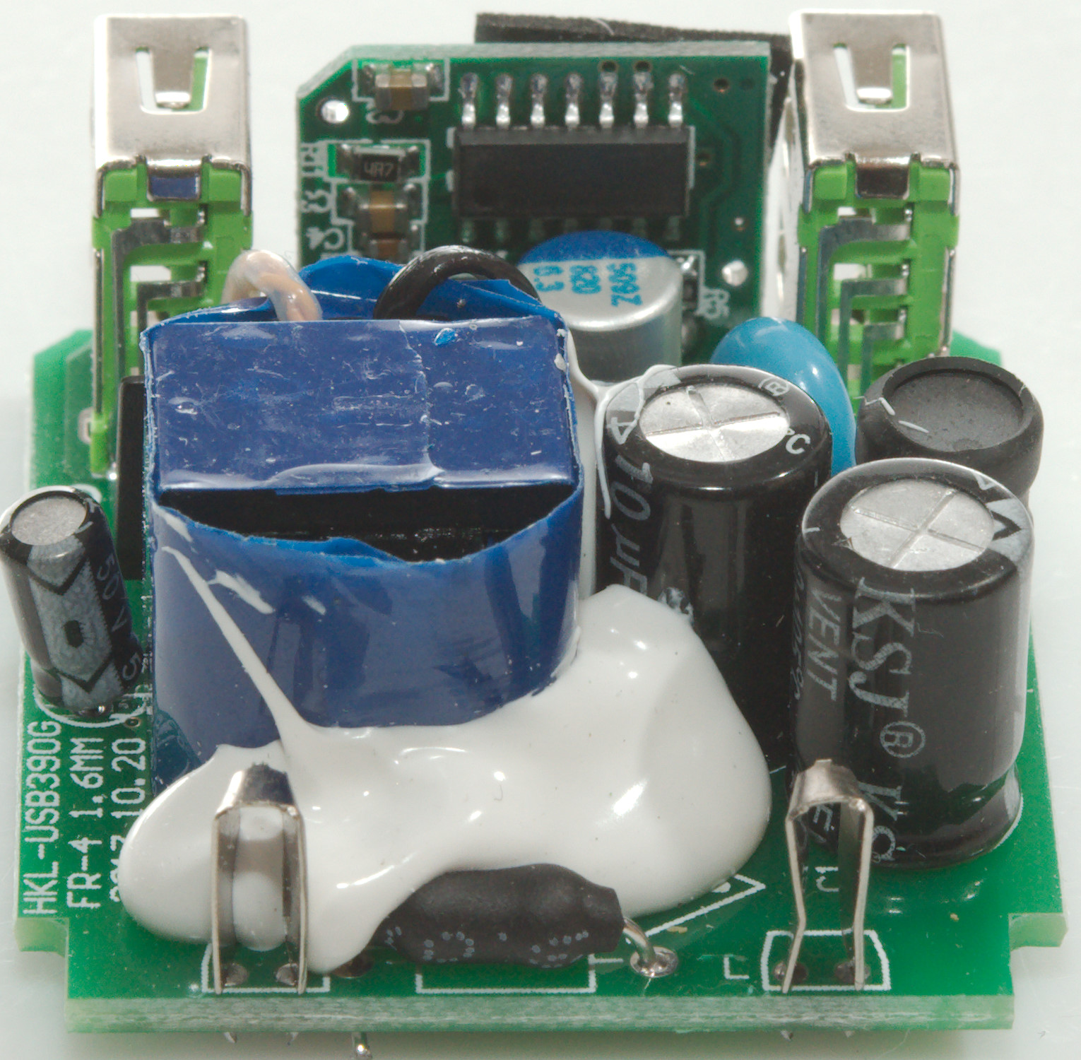
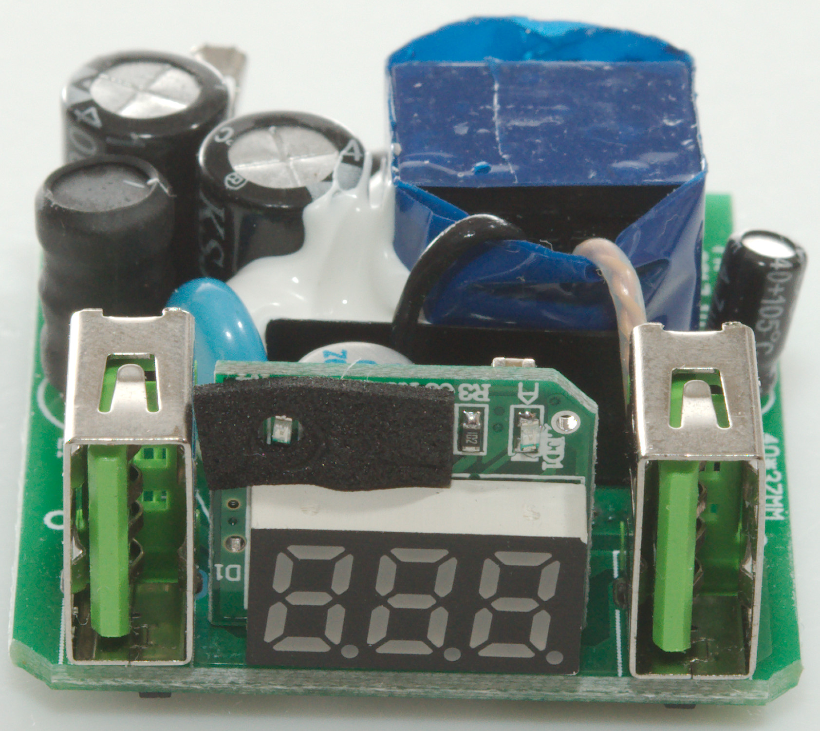
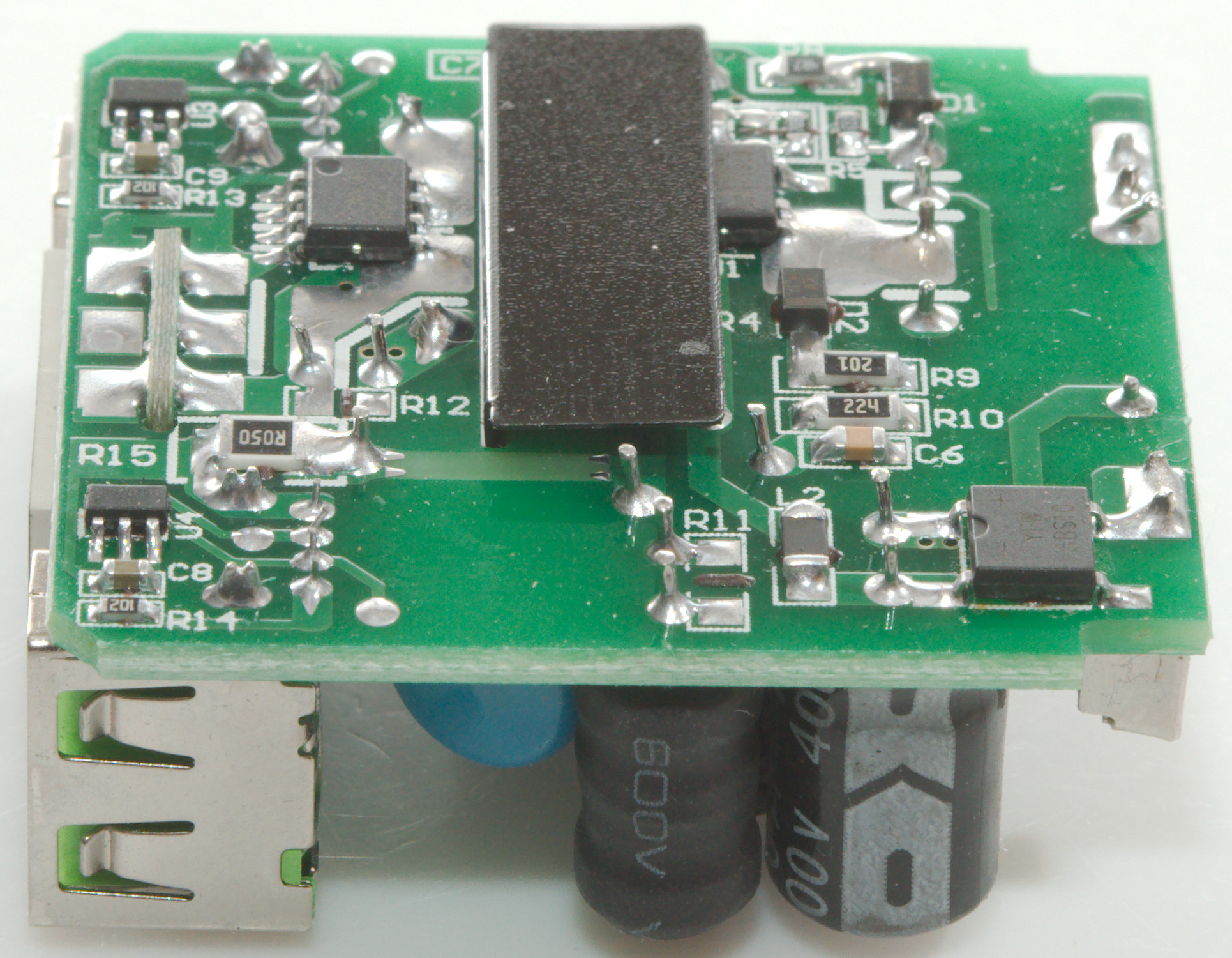
On this side is a fuse between the input terminals and a inductor (L1) between the two mains smoothing capacitors. The safety capacitor (CY1) and a small circuit board with the volt and ammeter.
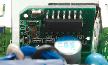
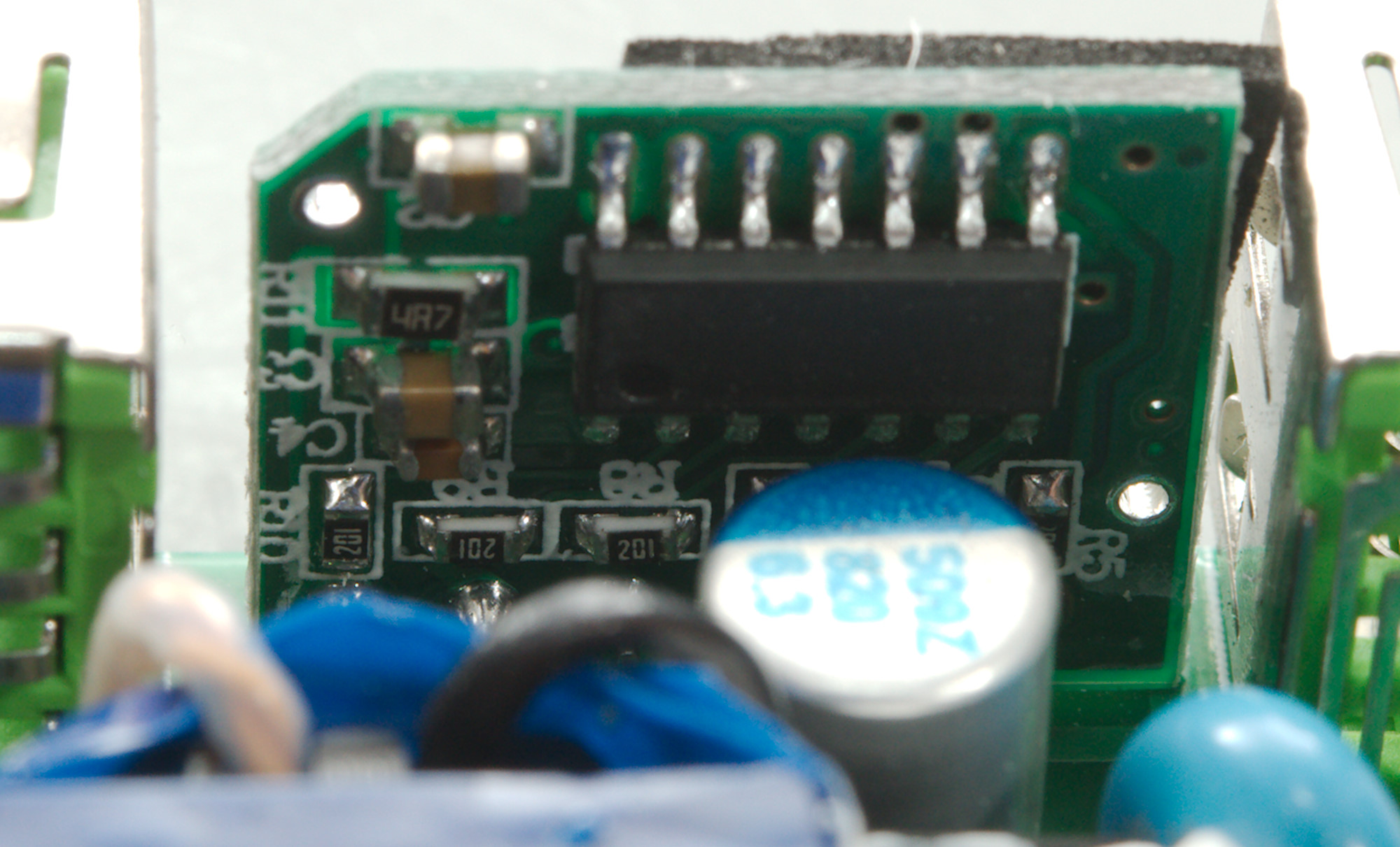
The unmarked chip to control the display and measure voltage and current is on a small circuit board together with the display.
The first picture is a view to the inductor and safety capacitor, the second picture shows the fuse.
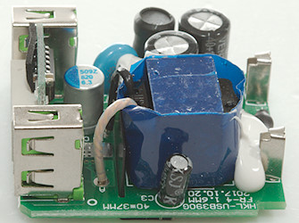
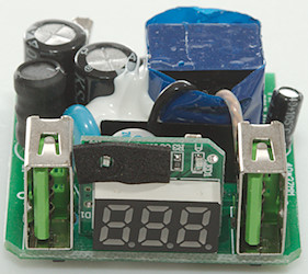
On the second picture is the display and the two diodes to show what it is measuring.
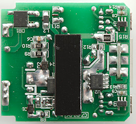
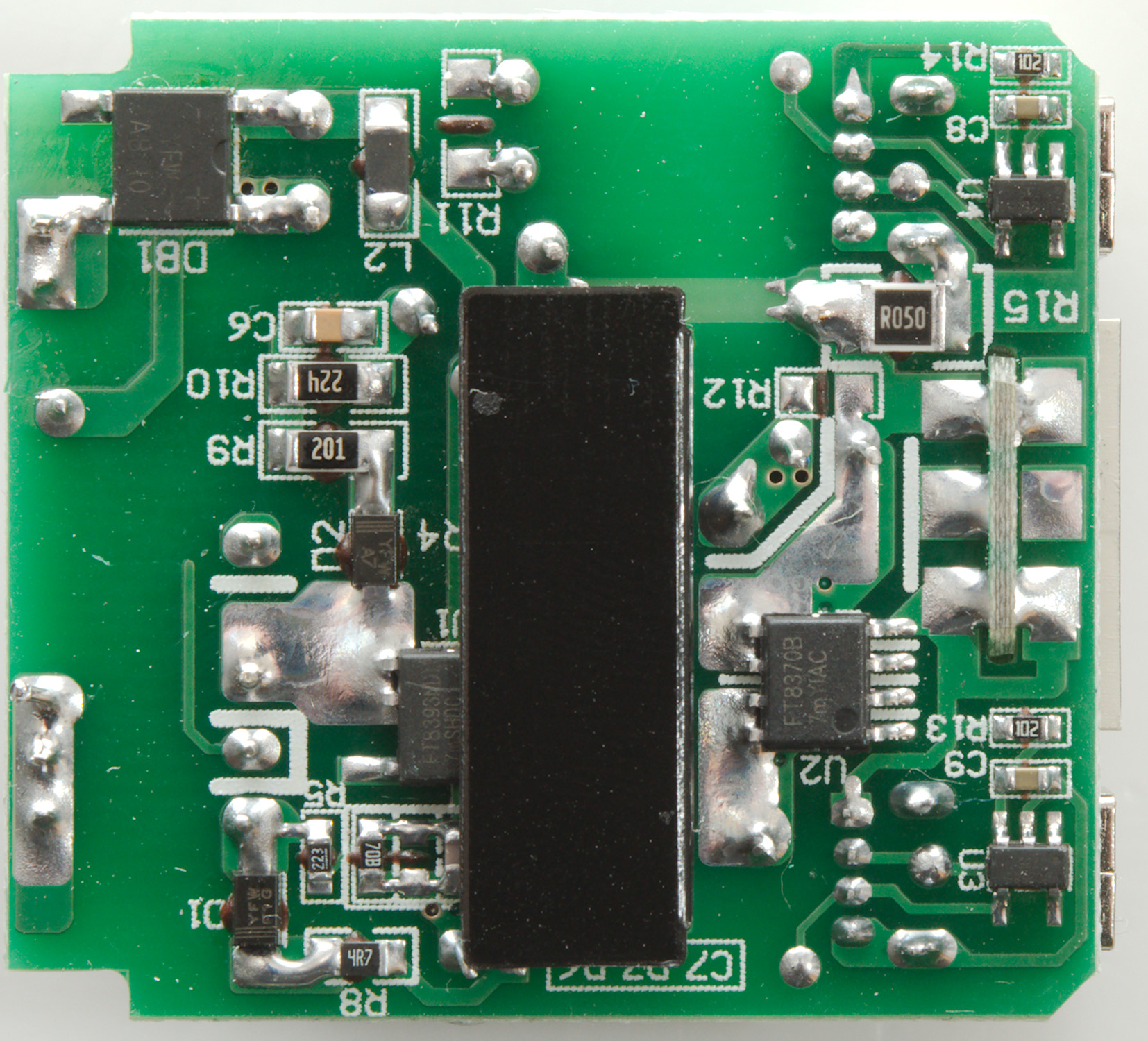
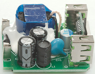
On this side is the bridge rectifier and the mains switcher (U1: FT8393). On the low volt side is the synchronous tectification chip (U2: FT8370B) and a resistor for measuring current (R15: R050), each usb output has their own auto coding chip (U3 & U4: UC2635).
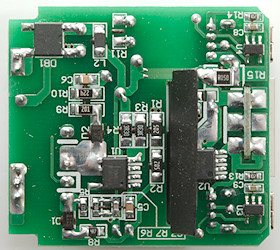

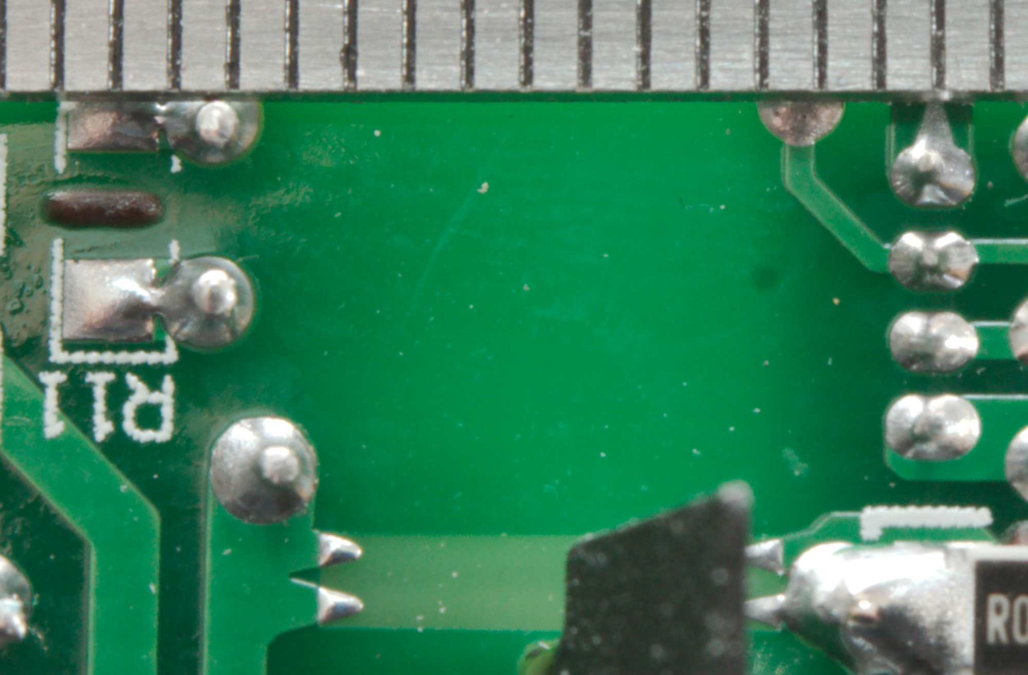
The distance is good, the black sheet helps with that.
Testing with 2830 volt and 4242 volt between mains and low volt side, did not show any safety problems.
Conclusion
The output power is fine for a charger with one output, but rather low for a charger with two outputs, especially when both outputs are coded for high current. The automatic coding works fine, the charger has low noise and I did not see any safety problems.
I like the current display and it is fairly precise.
The charger is a good usb charger for one high current device at a time.
Notes
Index of all tested USB power supplies/chargers
Read more about how I test USB power supplies/charger
How does a usb charger work?