Voltbot 4xUSB QC and power supply
Official specifications:
- Input voltage: 12V to 16V (max. 18V) DC or 100-240VAC with supplied adapter.
- Recommended power: 60 Watt
- Wireless: Wi-Fi: 802.1 b/g/n
- LCD: 72x49mm 480x320pixel
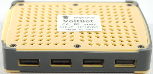
- Output sockets: 4x USB2.0
- Output voltage: 2.5V to 12.5V (Maximum limited by input voltage).
- Output current: 3A, peak 8A.
- Fast charge: QC1/2/3, MTK Pump-express, QC4, MTK Pump-express 2, Apple 2.4A, Samsung 2.1A
I got it from a reader
This device is a USB charger that can be powered from either mains with the supplied power supply or from DC. It can also work as a DC power supply.

I got it in a number of boxes, because it included a accessories packs.
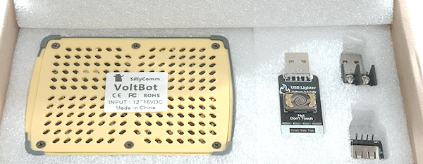
First box was the Voltbot charger.
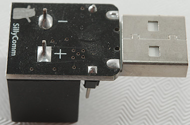
It included: Voltbot, USB lighter, USB to screw terminals adapter, communication adapter.
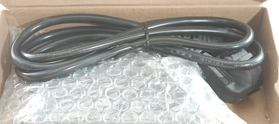
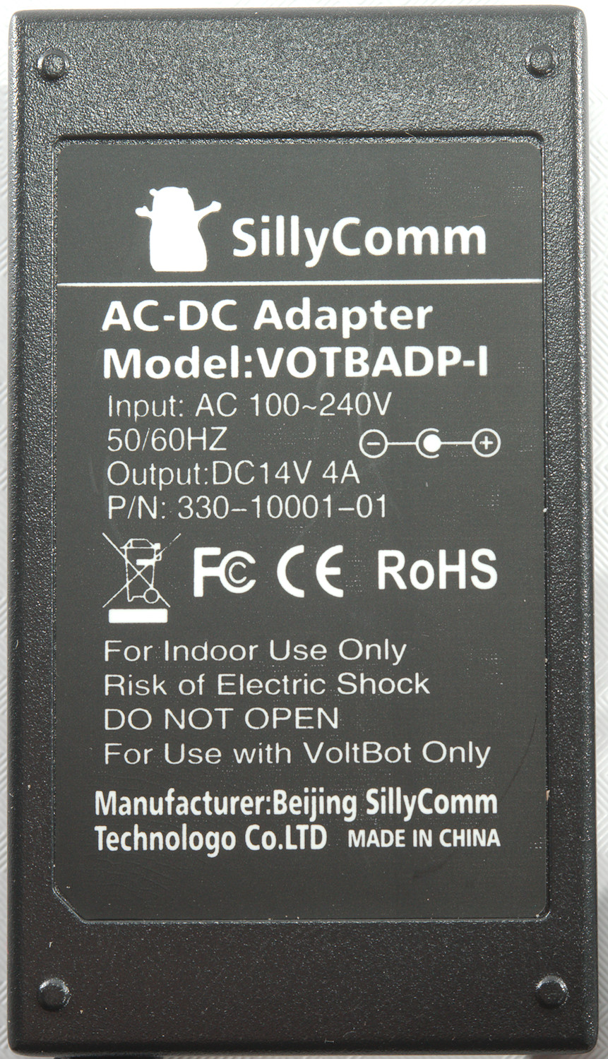
Second box was the power supply.
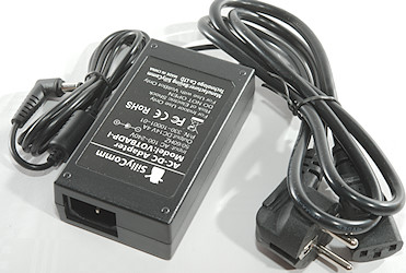
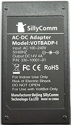
It is a 14V 4A, i.e. 56 Watt power supply.
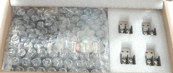
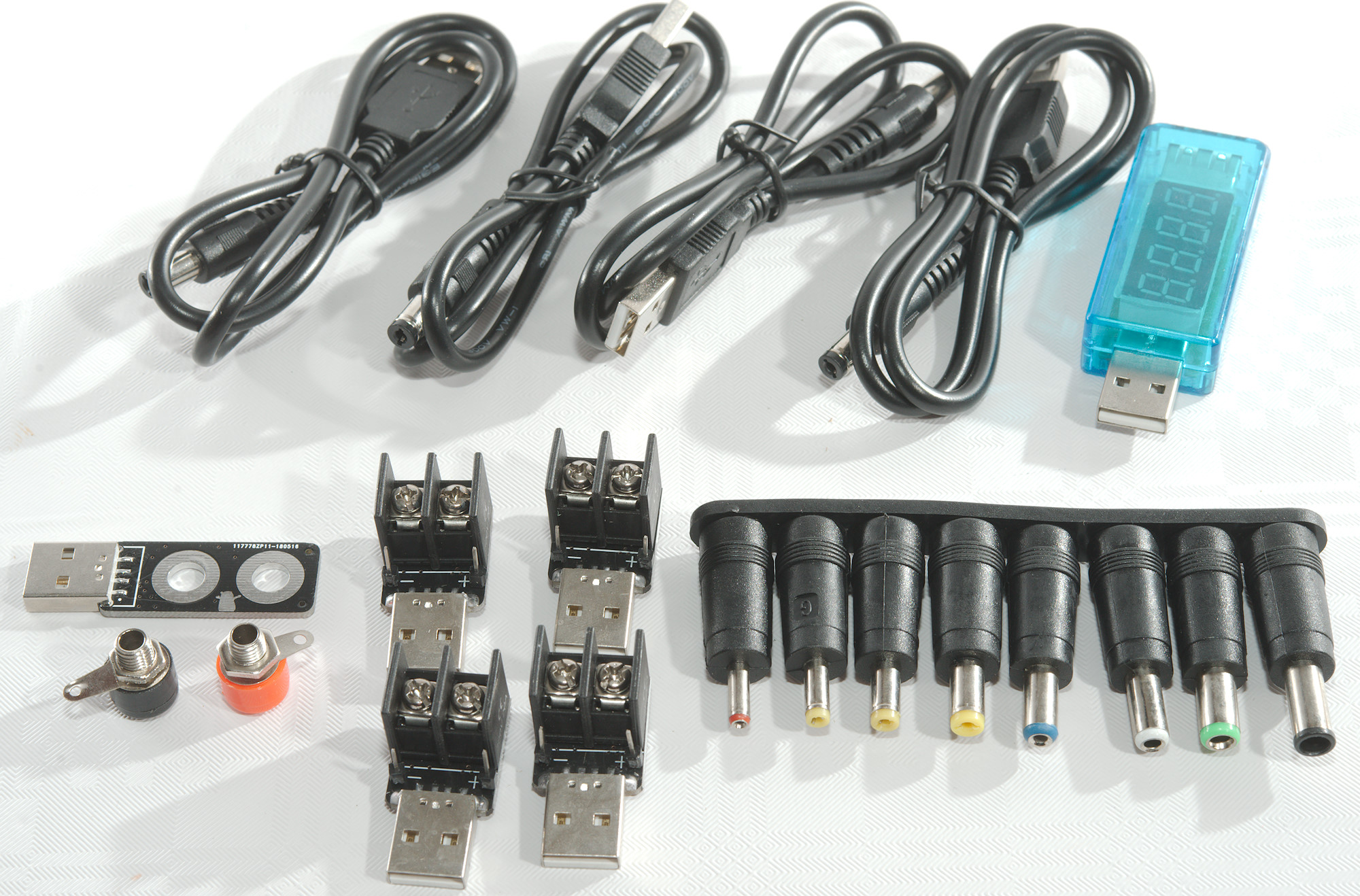
And the 3. box was the accessories
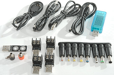
Counting all the accessories in the box:
4 USB to DC connector cable.
1 USB meter
1 USB to banana plugs adapter.
4 USB to screw terminals afapter.
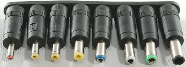
A set of DC connector adapters.
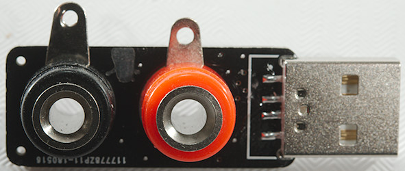
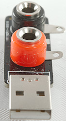

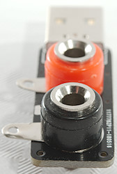
For a power supply it is nice to have banana plugs (I would have preferred binding posts).
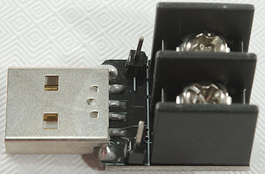
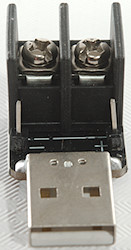
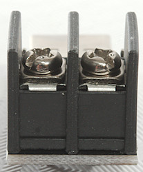
Screw terminals and also some small pins that can be used with dupont connectors.
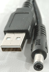
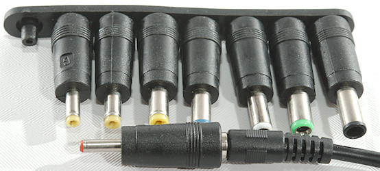
This cable can be used to power lots of other stuff with.
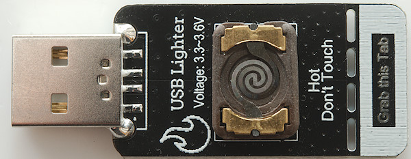
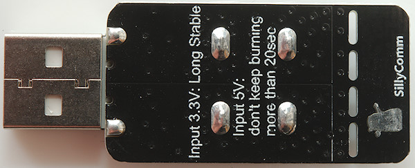
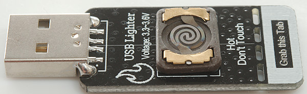
I wonder if there was a chain smoker on the development team for Voltbot, generally I do not see much use for this accessory.
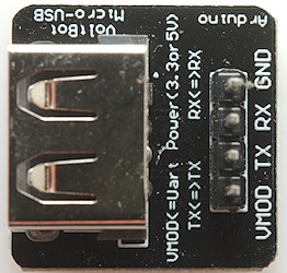
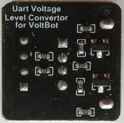
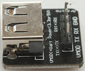
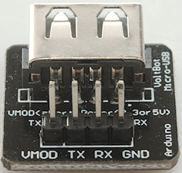
There is a 3.3V serial interface build into the Voltbot and with this adapter it can be used for 5V serial, the manual has an example with Arduino.
Again I wonder what the purpose is.
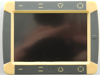
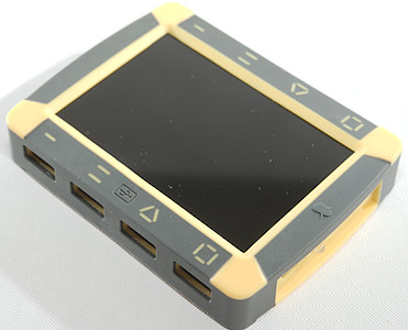
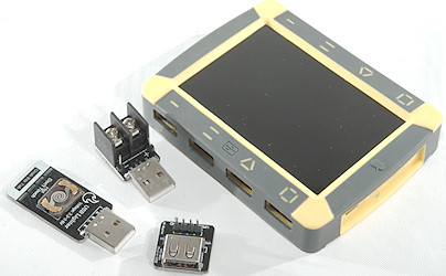
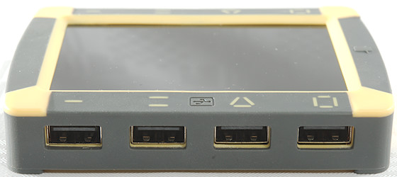
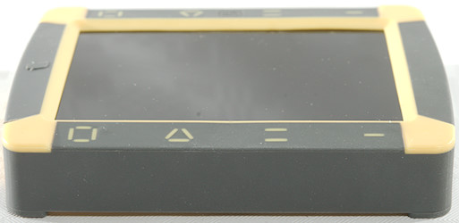
The Voltbot itself with four touch buttons at the top and four usb connectors at the bottom. The touch buttons are rather sensitive.
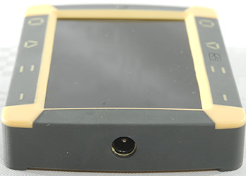
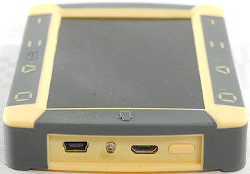
On one side is the power input DC connector, on the other side a USB connector for factory use and another USB connector with 3.3V serial signals. Between them is the light sensor for backlight. The switch is used to turn the screen on/off and turn the sound on/off.
The buttons are NOT disabled with the screen off.
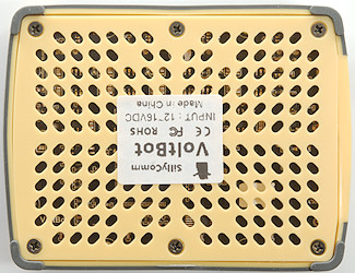
At the bottom is a lot of holes for cooling.
Display

Power on logo, it takes about 8 seconds to startup.
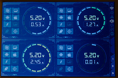
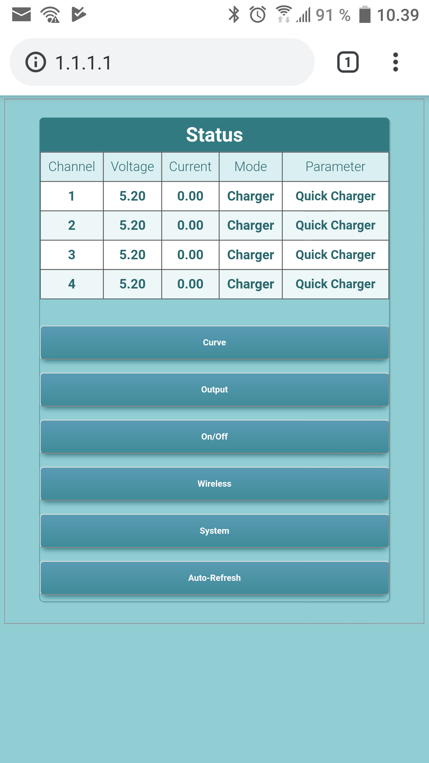
The normal screen, with lots of mostly useless icons. The all have some meaning, but I do not really see the point in most of them. In my opinion fewer, but larger icons would have been better.
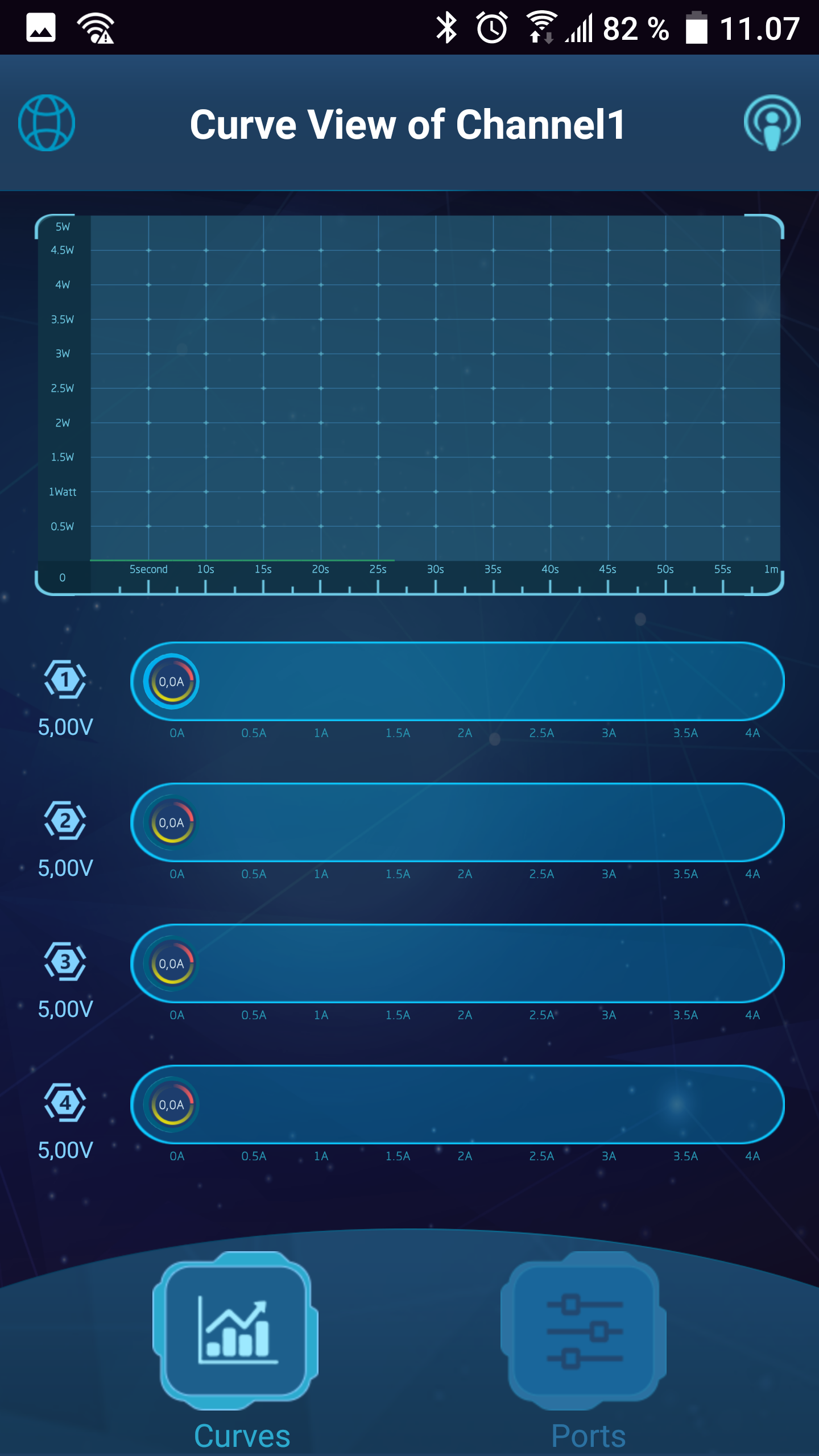
The voltage and current is nice, the ring around them is power, 5 Watt for each turn.
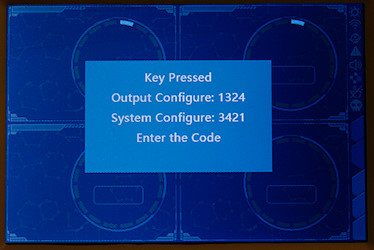
Using the touch keys requires a lot of presses. When you hit the first key this message pops up, this do not mean you can now press 1324 or 3421, because the key used to pop up this message is counted as the first key.
This system also means any use of keys always must start with one of the above two sequences, i.e. to do anything you have to press at least 6 buttons.
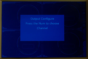
Pressing 1324 will bring up this menu where you can select one of 3 functions:
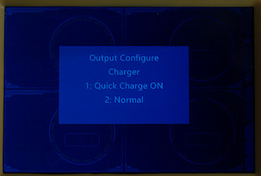
Charger mode, is fast charge support enabled or not.
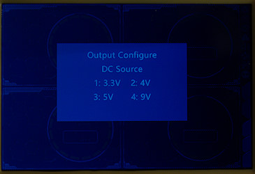
Some common voltage for the power supply mode, more adjustment requires a computer or phone.
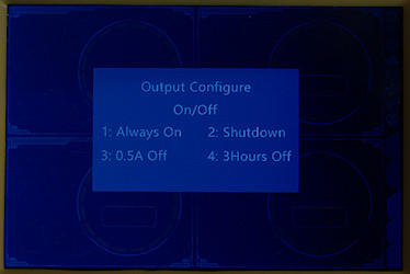
On or off mode, automatic shutdown when current drops below 0.5A or turn off for 3 hours.
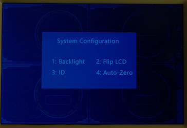
Pressing 3421 brings up this menu
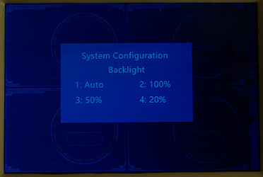
I prefer the backlight at 100%, this makes it easier to see the screen, but it also means more heat in the Voltbot. In my test I used a lower setting.
Android application and web


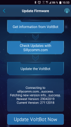
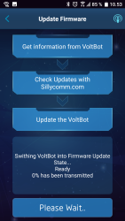

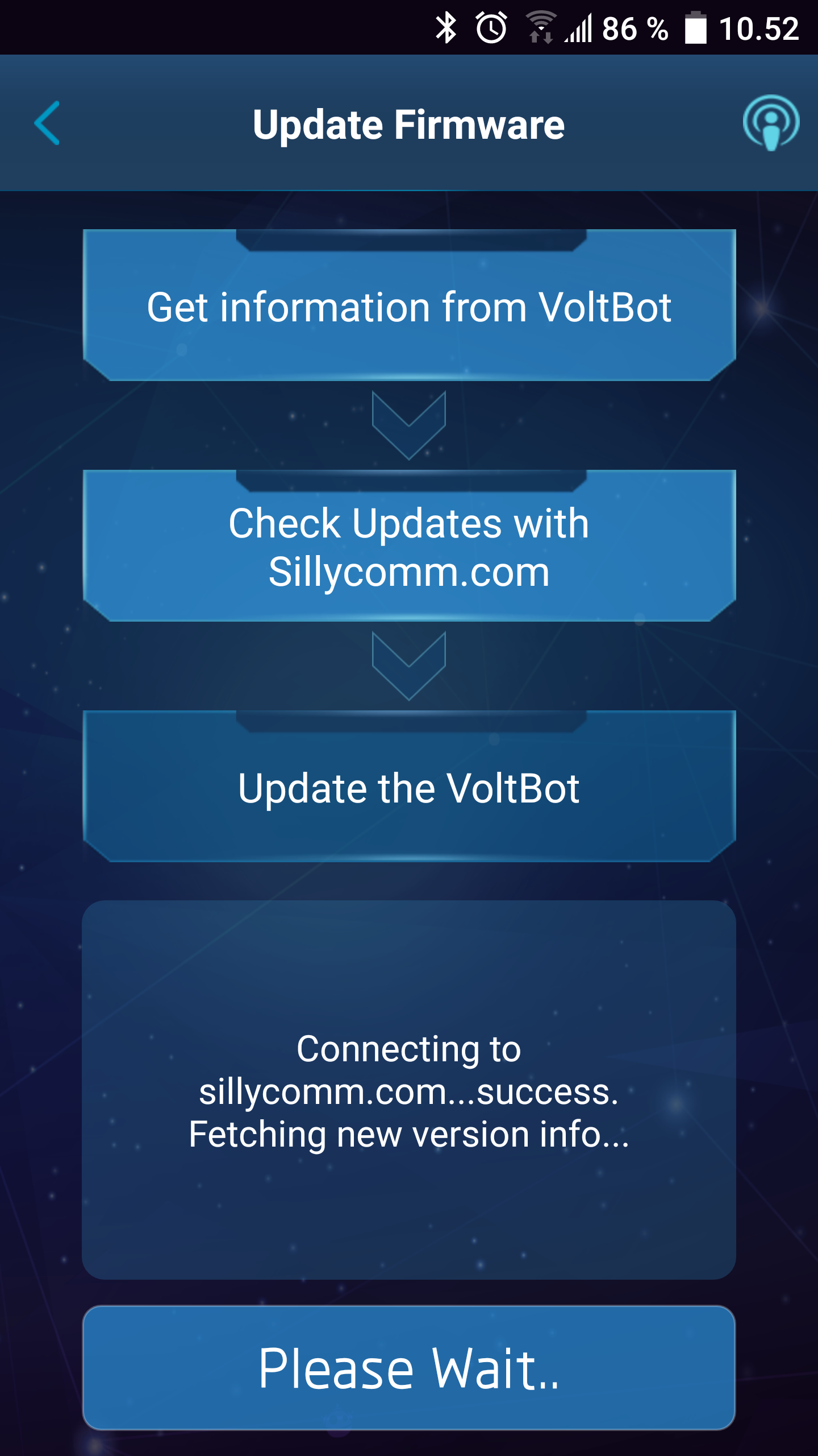
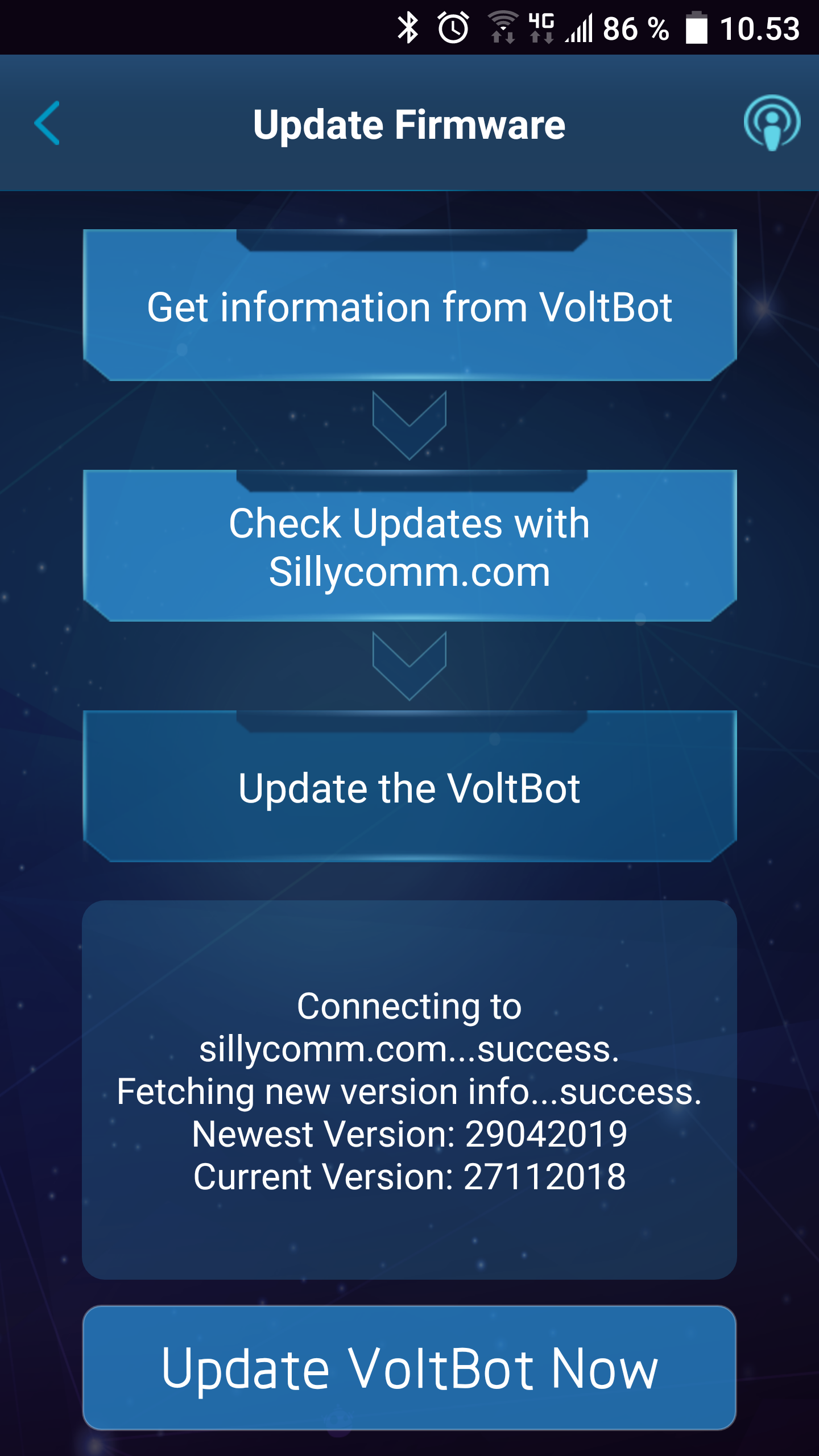
First time I used the application I had some problems with the connection, it insisted that I updated the firmware, but because I was on the private Voltbot network I could not download the update. Switching off Voltbot allowed the software to download the new firmware and next time I turned on Voltbot it was updated (It took fairly long time to update).

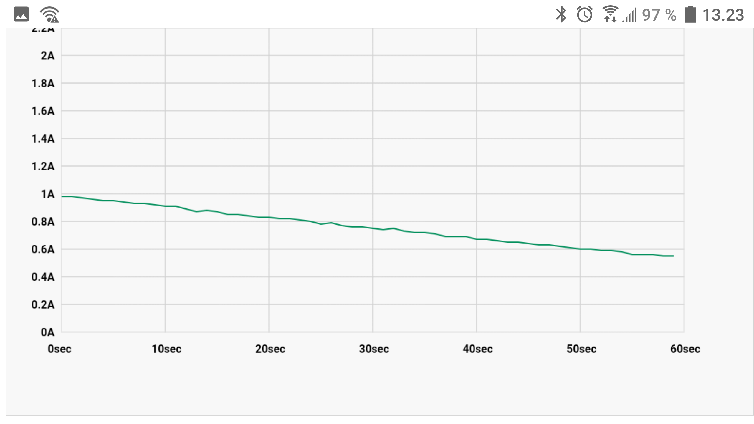
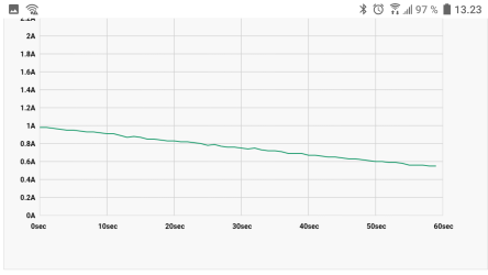
This is the main screen. Touch one of the four bars to select curve for that channel. Touch the curve or slide sideways to get a better curve view. Touch the icon with sliders to adjust output.
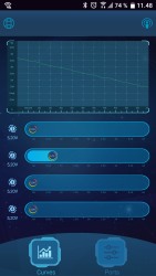
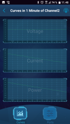
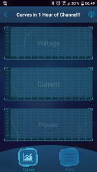
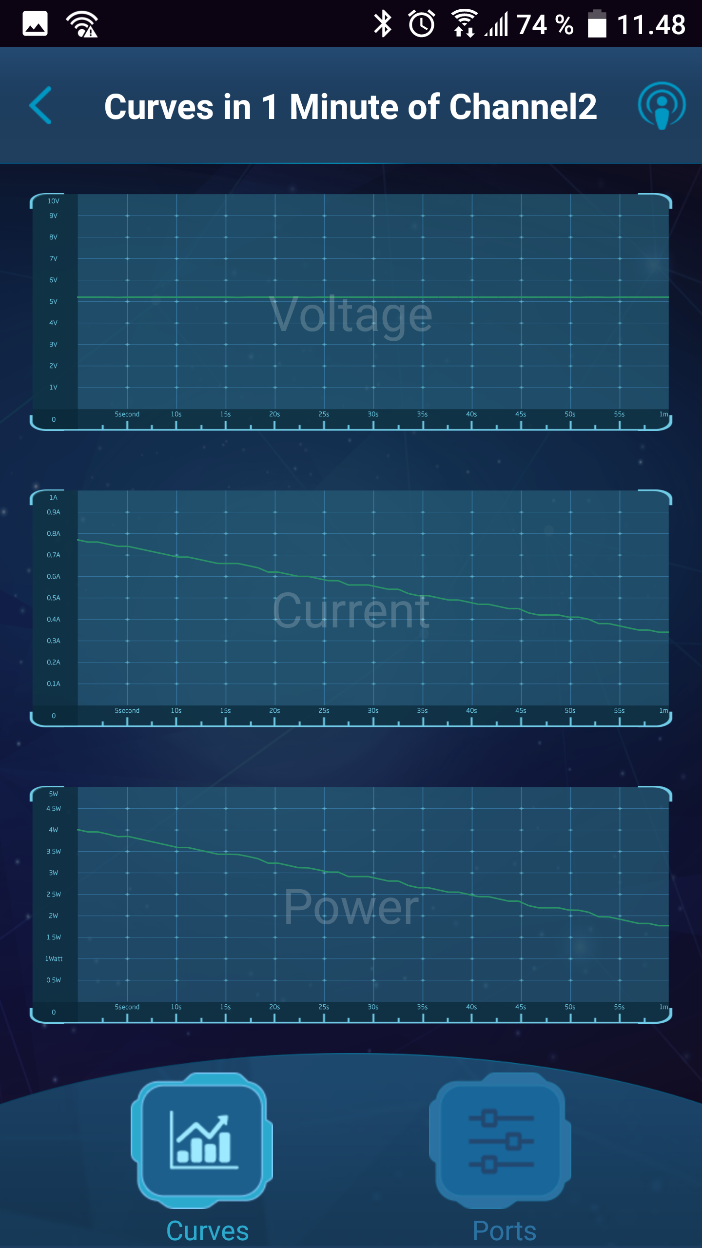
The curve view comes with 4 different time scales (6 seconds, 1 minute, 1 hour, 4 hours) and it is possible to zoom on a specific curve, by touching it. The curves has the newest data on the left!
The curves are collected inside the charger, i.e. they are always available.
There is one small problem with them: the charger will clear a curve when a channel overloads, i.e. it is not possible to see at what current the charger overloaded or how the current was up to that point.
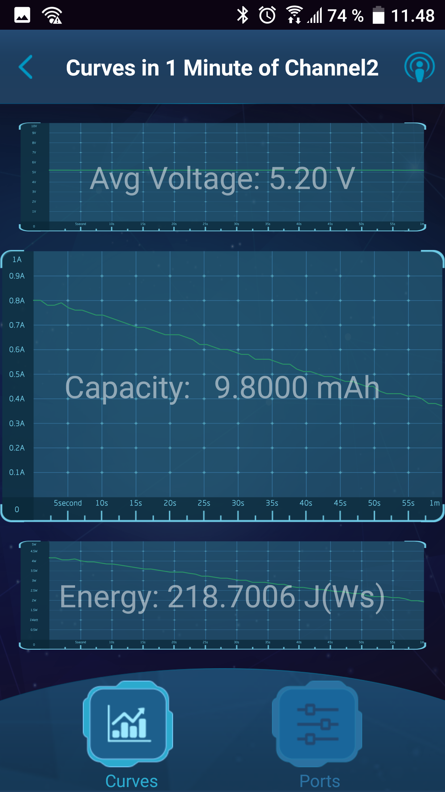
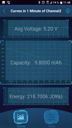
A long press on a curve will copy the data for that curve into the clipboard (Only value, not time), I would have preferred a full CSV format with columns for time, voltage, current, power, capacity and energy, that would have been much more useful.

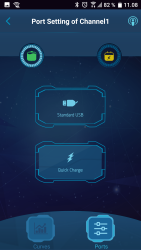
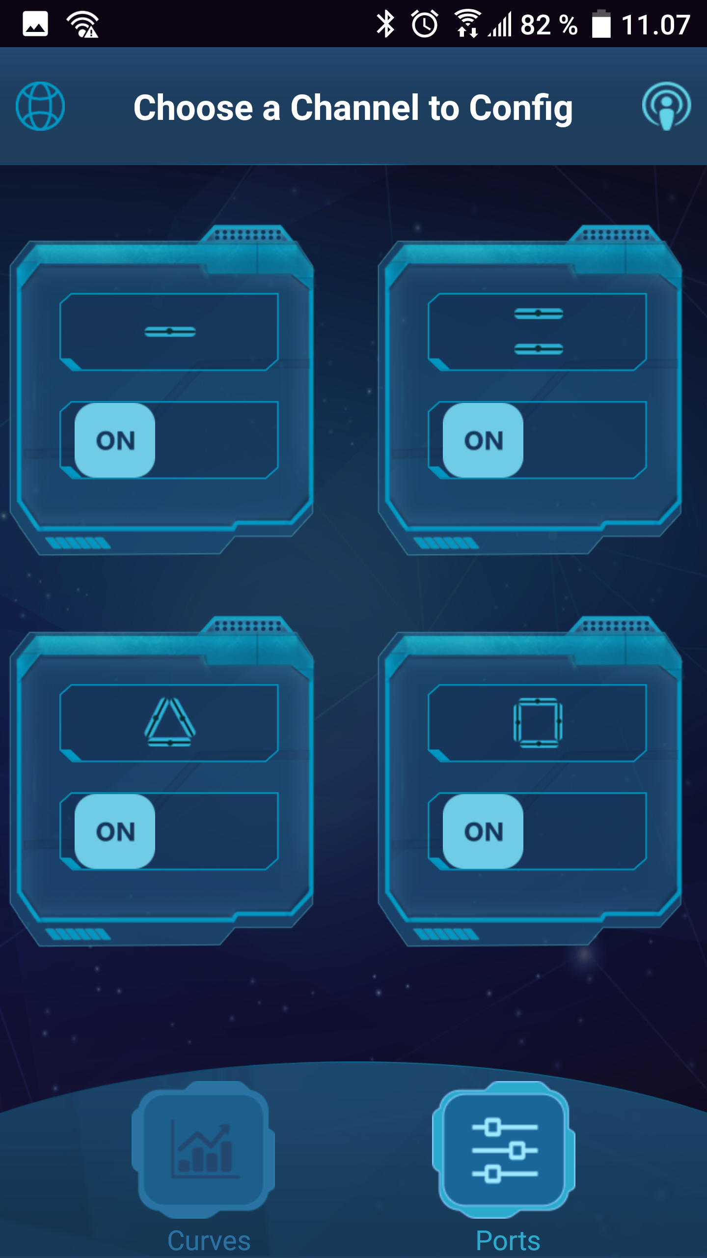
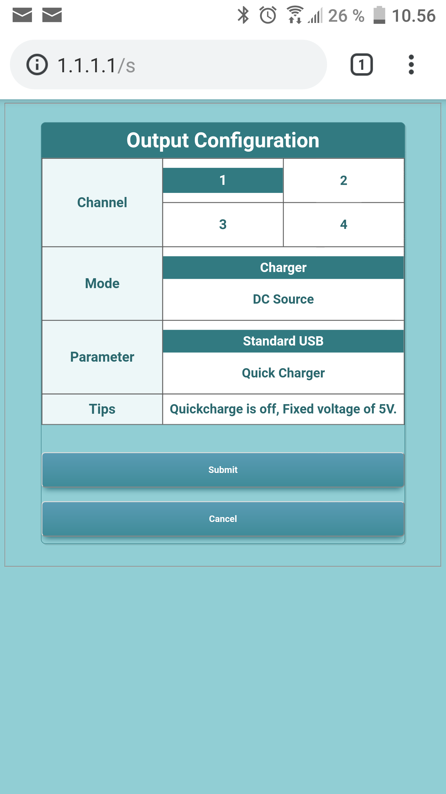
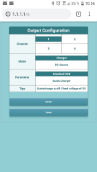
The output adjustment menu has two screens for each channel. Touching on the top part of each icon will bring up the mode selection.
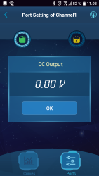
Here it is possible to select dumb charger, fast charger or DC power supply. In the DC supply mode the voltage can be adjusted from 3 to 12V, not the full 2.5V to 12.5V range (Use web browser for that).
The numeric input is not very good, it is necessary to delete digits, before entering new digits.
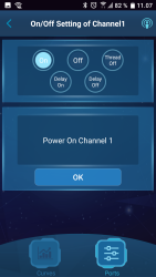
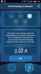
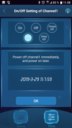
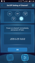
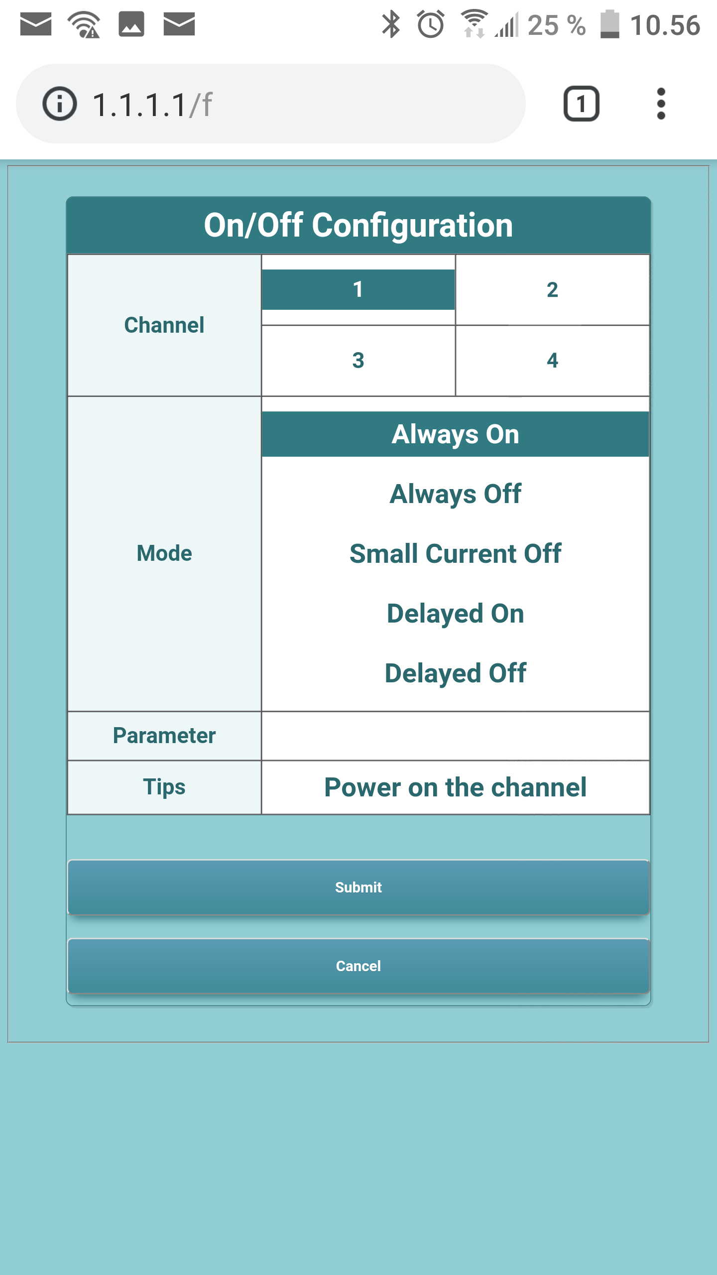
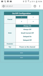
The lower part of the adjustment icon shows the options for on/off. There is the standard on and off setting, a automatic turn off when current is below a specified value (Can only be set when current is above that value) and times on or off. Again the entering of values requires deletion of digits before typing new in.
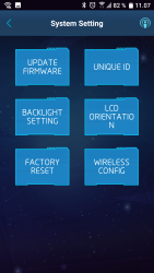
There is a couple of system options. I tried to join my local WiFi, but I never had success.

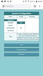
The web access seen on my phone (My tablet would not connect)
The curve option is made for a larger screen.
Measurements
- Power consumption when idle is 3 to 3.5 watt depending on display brightness (Power supply is 0.6 Watt).
- USB outputs in fast charge mode is auto coding with Apple 2.4A, Samsung, DCP, QC3, Samsung-AFC
- It is supposed to support MTKPE, but I did not detect it.
- USB outputs in normal mode is Apple 2.4A, Samsung, DCP
- Minimum QC3 voltage is 5.2V
- With sound on there is sound on keypress and when power goes above 5 Watt
- Weight Voltbot: 87.8g, power supply: 222g
- Size Voltbot: 98 x 75 x 17mm, power supply: 136 x 62 x 31mm
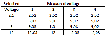
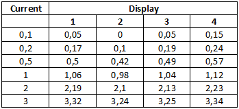
The voltage display has a good precision, but I am not impressed with the current display.
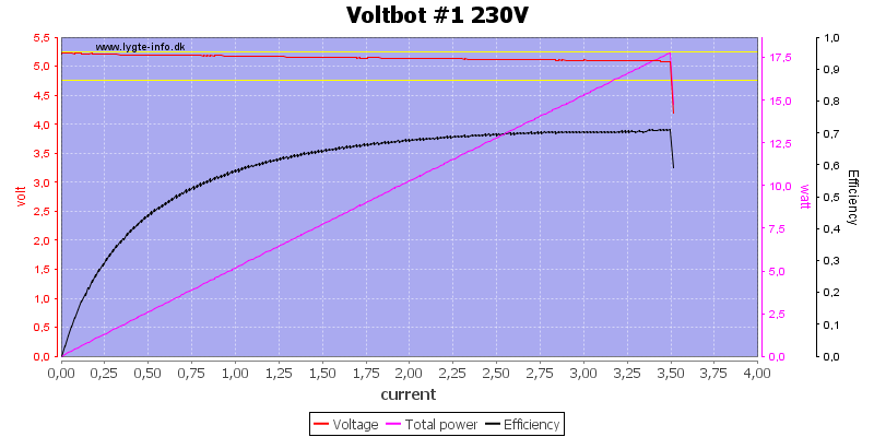
All outputs basically looks the same and over current trips at 3.5A (Display shows 4A)
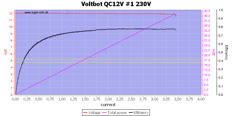
Using QC at 12V will not change the current limit.
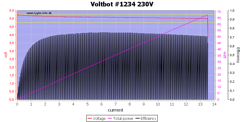
Running all outputs simultaneous gave me 13A, I do not know if it was the power supply or the Voltbot that shut down.
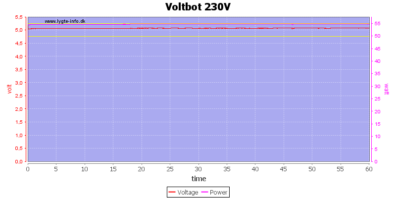
I used 2.7A one each channel for the one hour test.
The temperature photos below are taken between 30 minutes and 60 minutes into the one hour test.
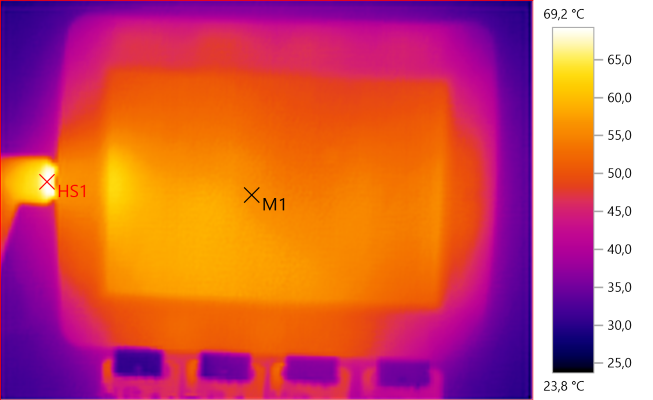
M1: 56.3°C, HS1: 69.2°C
The input connector is rather warm.
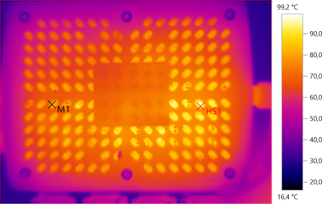
M1: 82.3°C, HS1: 99.2°C
The circuit board is very warm and above the rating of some of the parts.
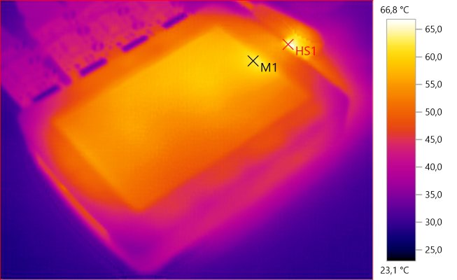
M1: 62.1°C, HS1: 66.8°C
And the output rectifier.
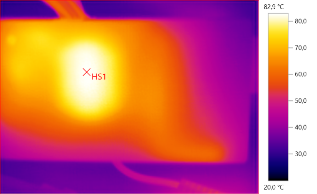
HS1: 82.9°C
The power supply is also warm, this is the transformer.
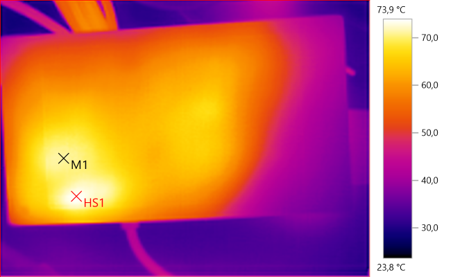
M1: 71.1°C, HS1: 73.9°C
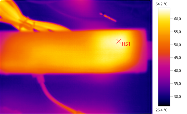
HS1: 62.9°C
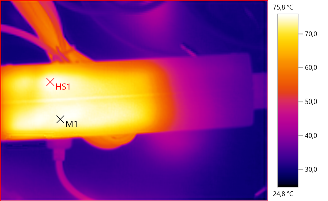
M1: 75.2°C, HS1: 75.8°C
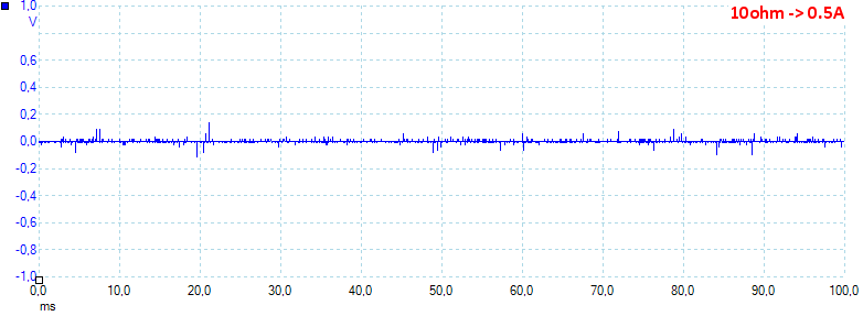
At 0.5A load the noise is 9mV rms and 379mVpp.
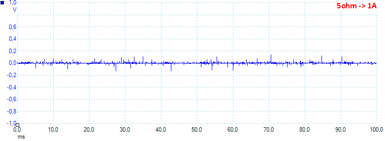
At 1A load the noise is 20mV rms and 882mVpp.
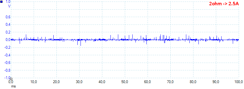
At 2.5A load the noise is 11mV rms and 375mVpp.
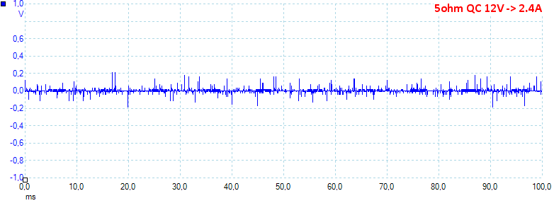
At 12V 2.4A load the noise is 16mV rms and 407mVpp.
More Measurements
These are measurement I usual do on a regular power supply. Blue is output, red is load.
- Power consumption from 16V DC is 150mA with 100% backlight and 130mA DC with display off.
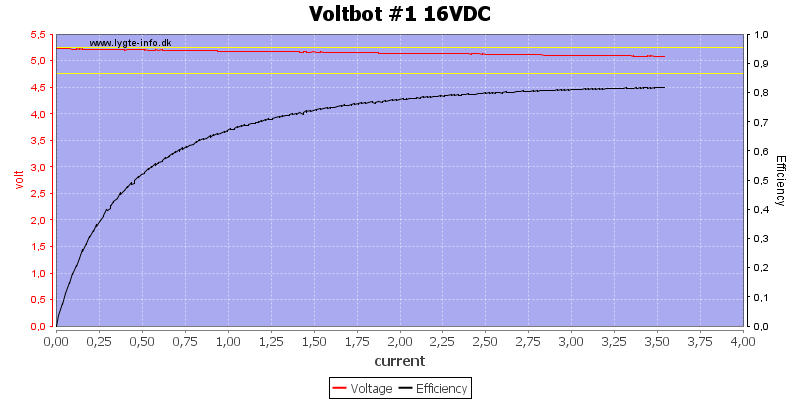
Using a DC supply will, not very surprisingly, improve the efficiency and not change anything else.
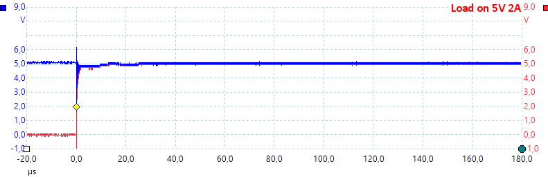
The output is stable when a load is connected.
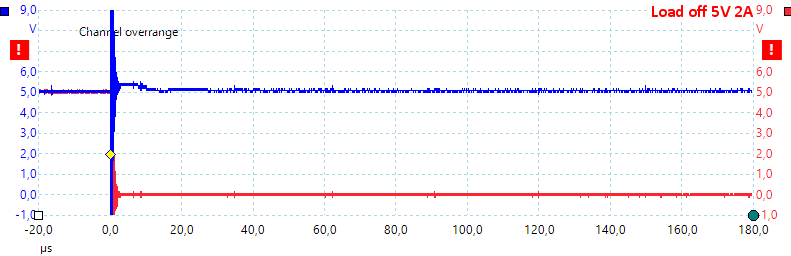
There is a small overshot when a load is removed (The thick vertical line is from wires and wire wound resistors).
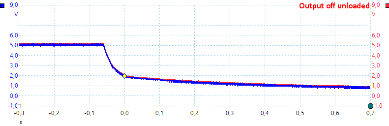
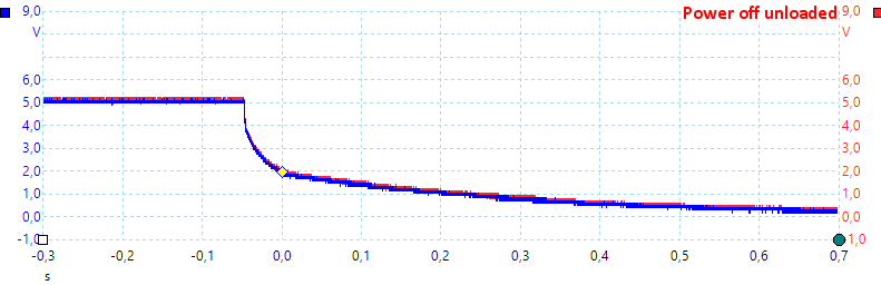
It takes a few fraction of a second to turn the output off, it is not very important if it is loaded or not.
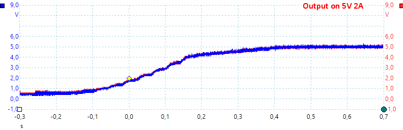
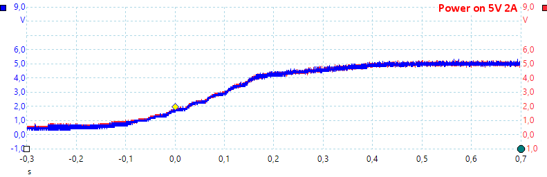
Turning on is also done slowly, a loaded or unloaded do not change this.
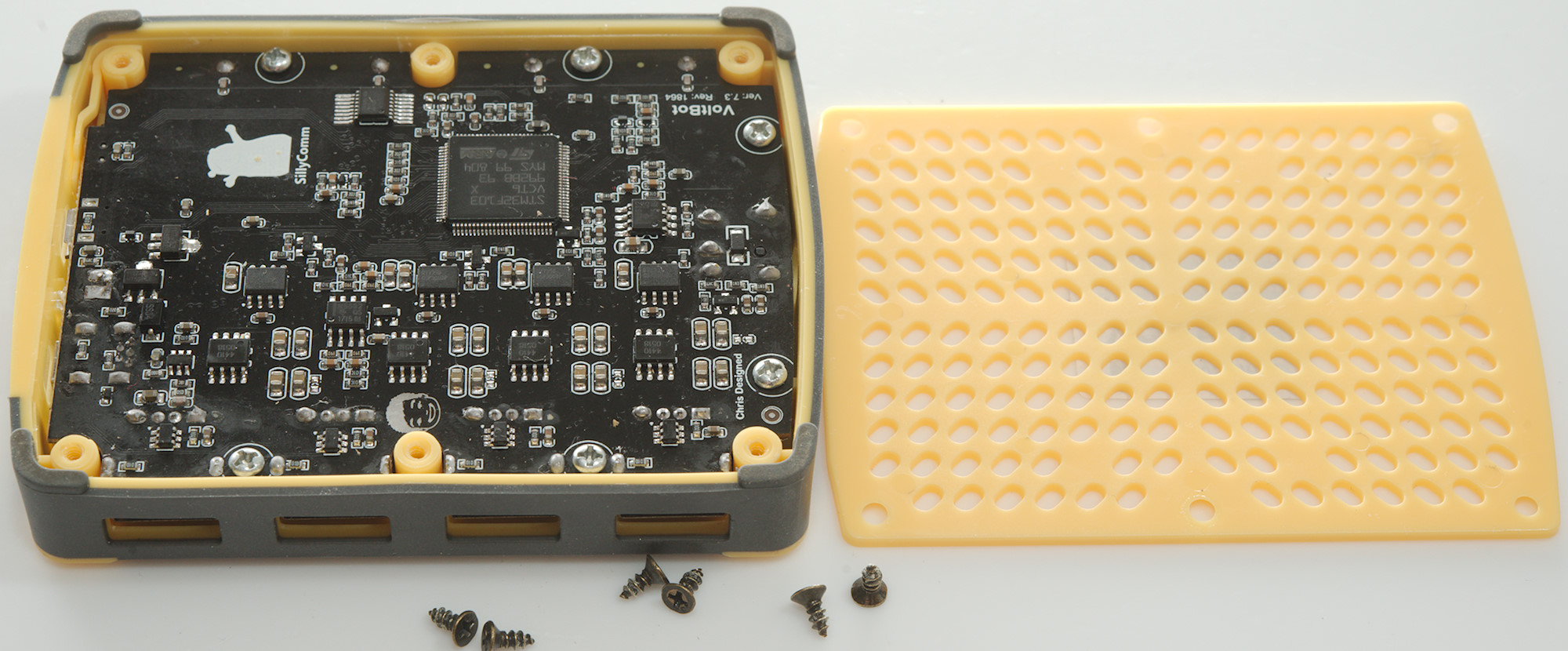
Tear down
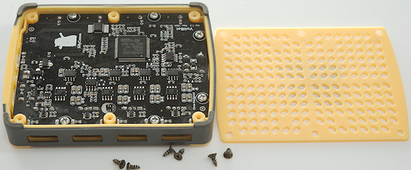
To remove the bottom I had to remove 6 screws.

There was 6 more screws to get the circuit board out.
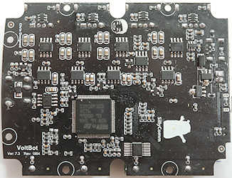
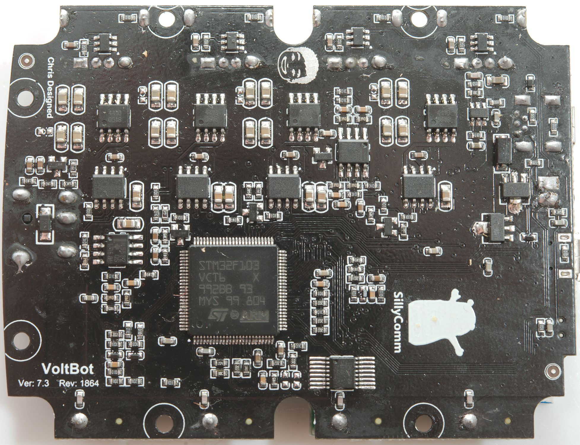
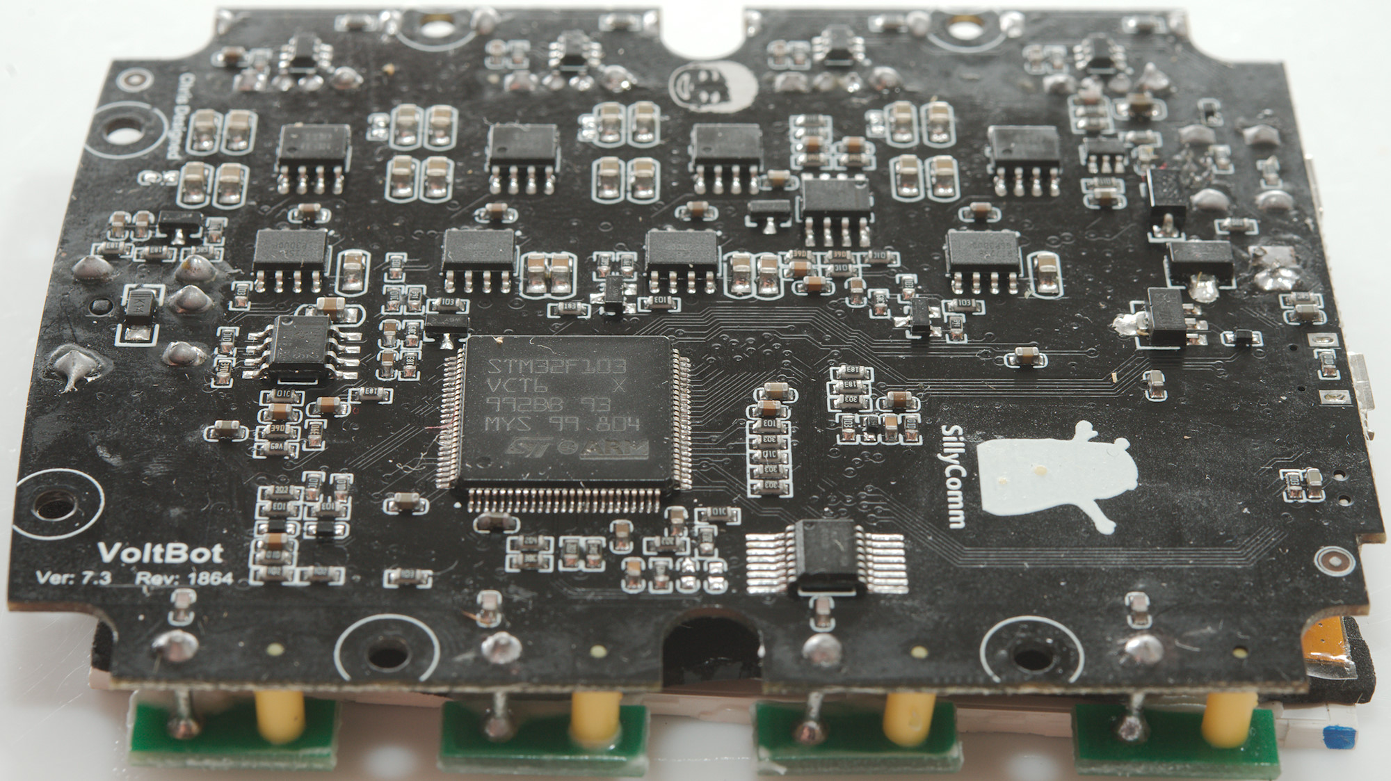
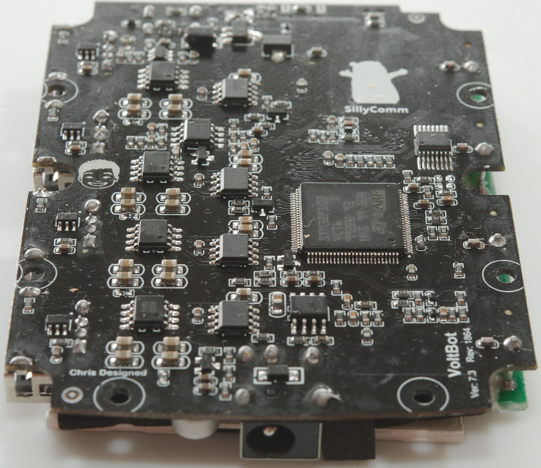
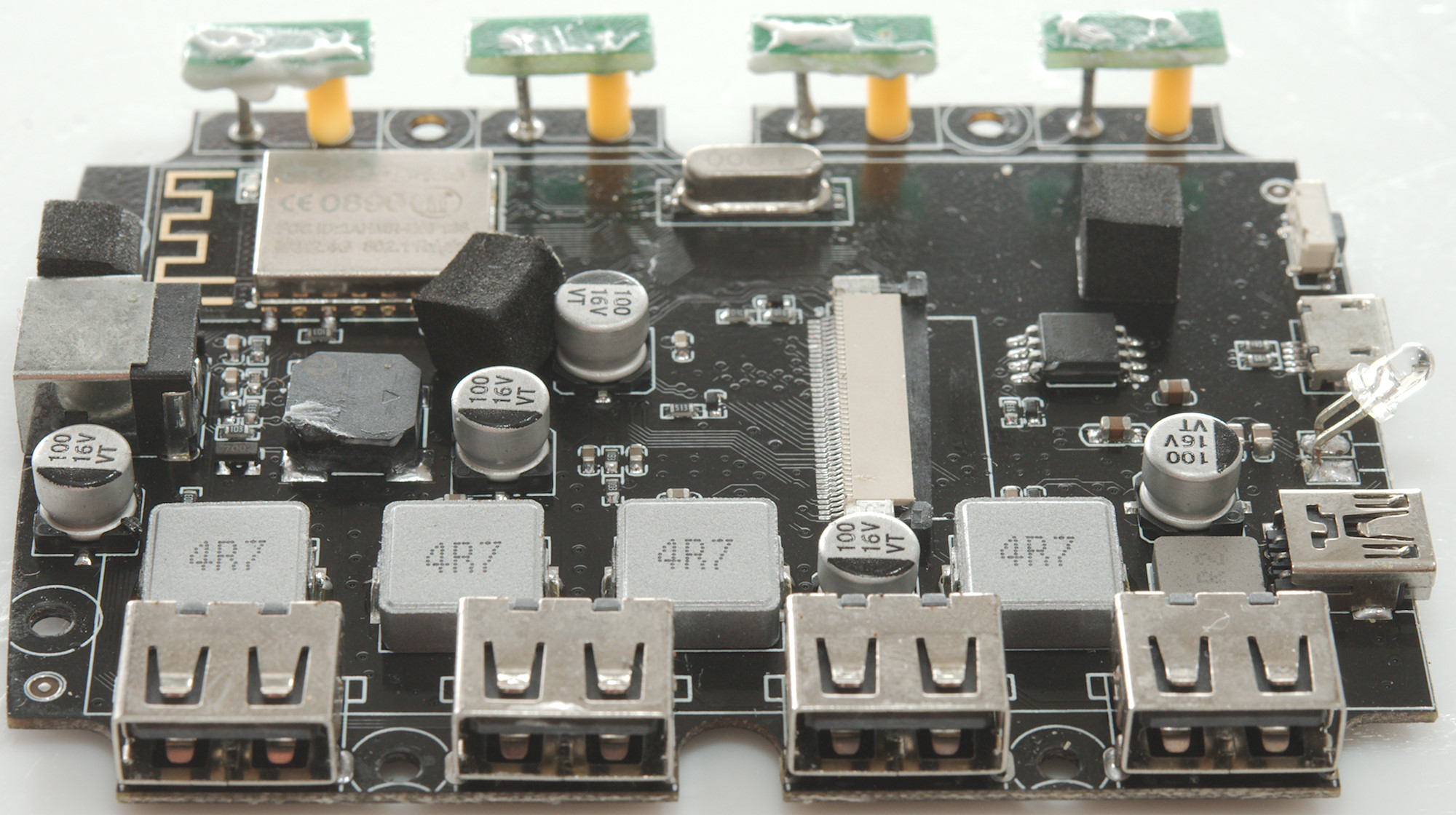
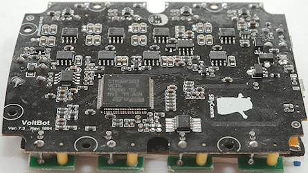
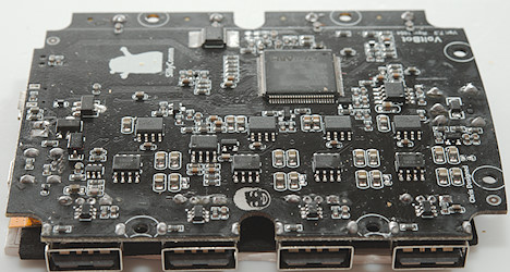
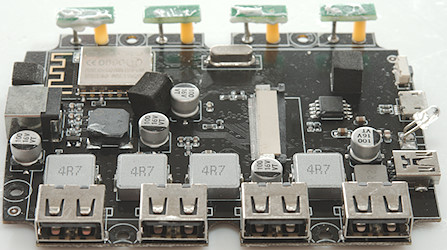
The big chip is the processor (STM32F103VCT6 Arm Cortex M3, 12 bit ADC/DAC). The synchronous output switchers (RT7258) uses a external transistor to turn the output on/off (SI4410DYTRPbf). Each output has a small chip for auto coding near the USB connector. There are two chip (N5532, probably NE5532 dual OpAmp), that may be used for amplifying current sense, but I am missing resistors for current sense, maybe they measure across the output transistors and that is the reason for the low precision?
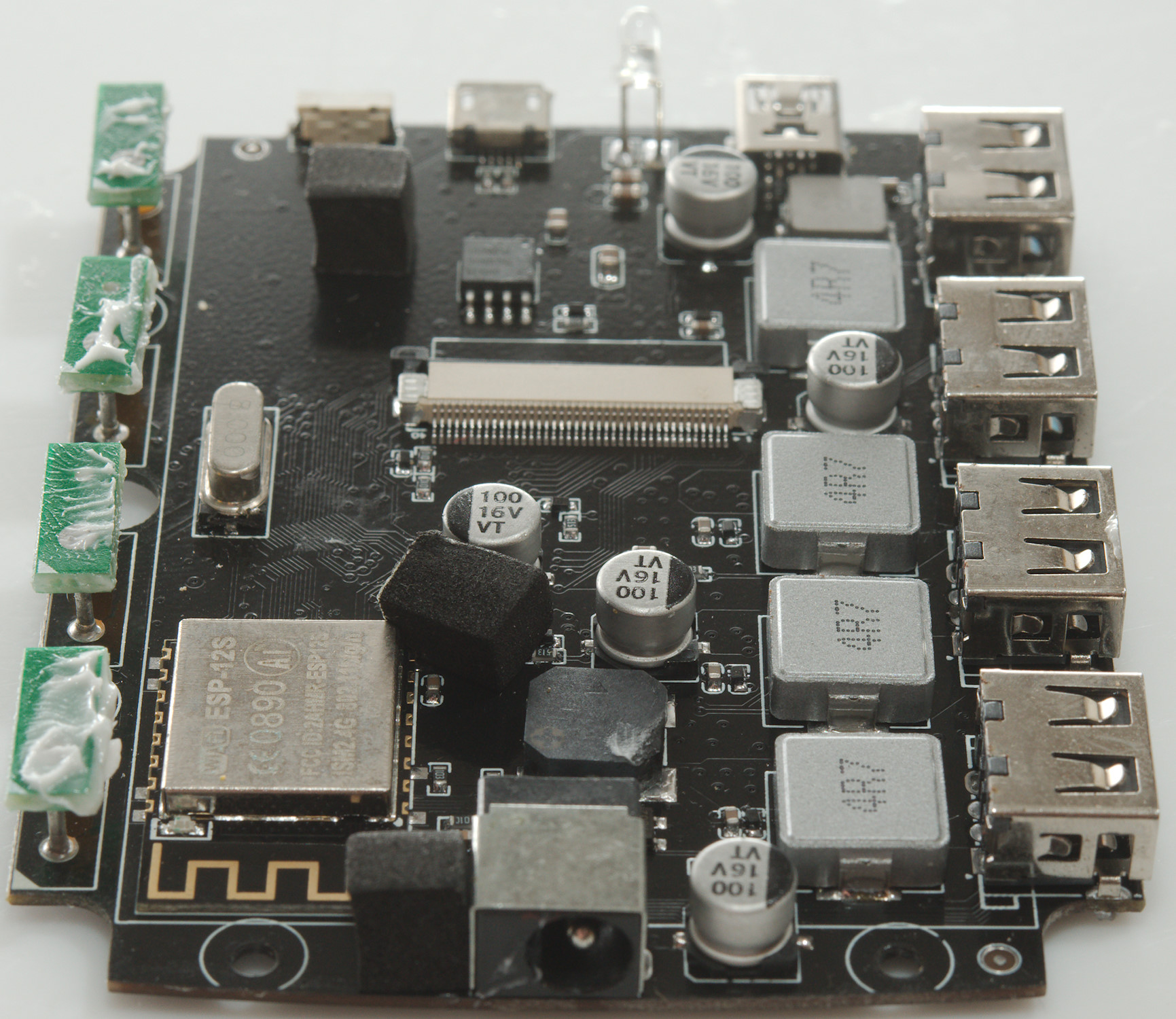
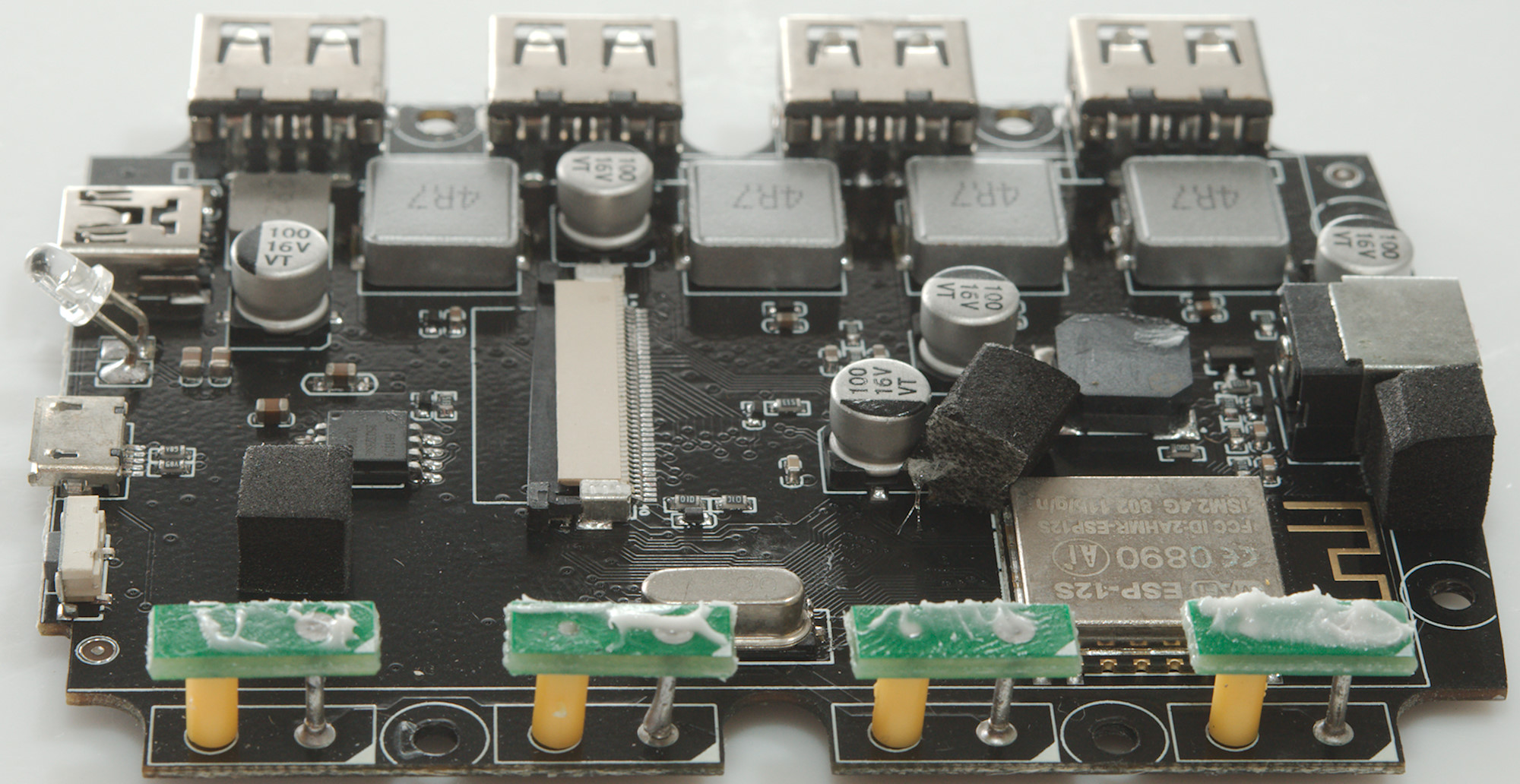
There are two 3.3V regulators (1117-3.3), the 6 pin chip near them is probably a switcher for pre-regulating internal supply (Diode nearby and inductor on the other side makes this plausible). I could not read the number on the 16 pin chip, but it is connected to the touch buttons, i.e. it must be a touch controller.
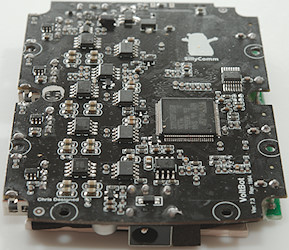
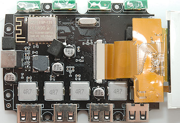
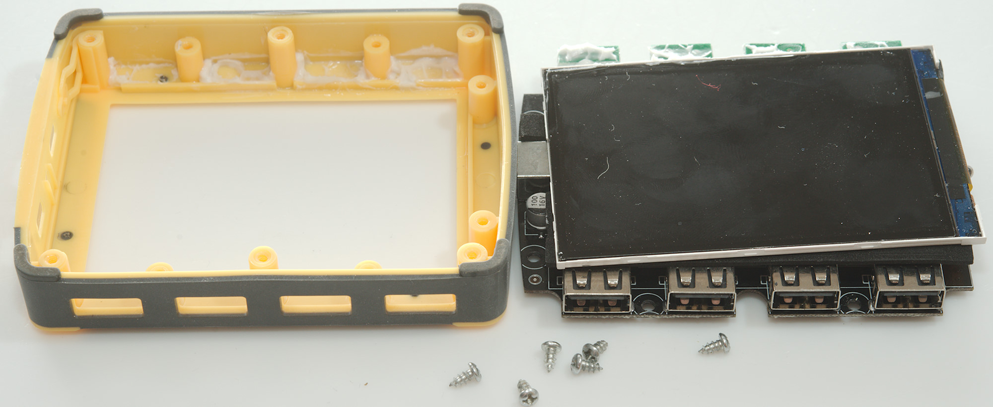
Om this side is all the larger parts and a cable to the display.
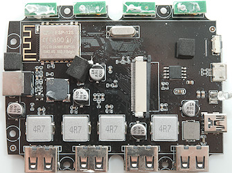
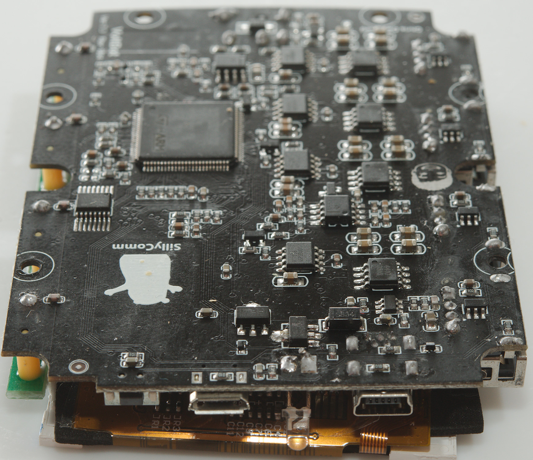
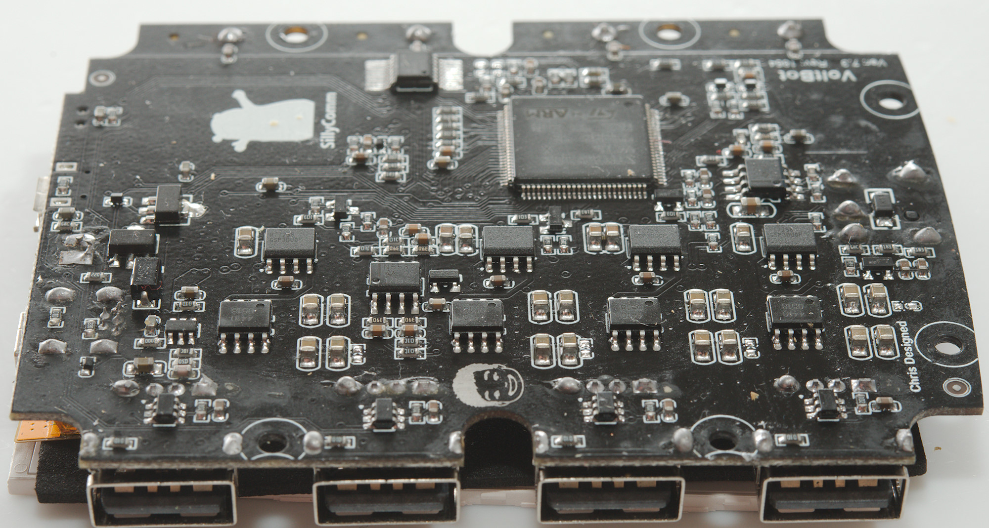
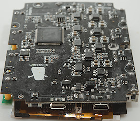
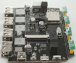
On this side is the four output inductors, a inductor for internal supply and probably a input filtering inductor. The crystal for the processor is also here and the WiFi module (ESP-12S).
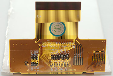
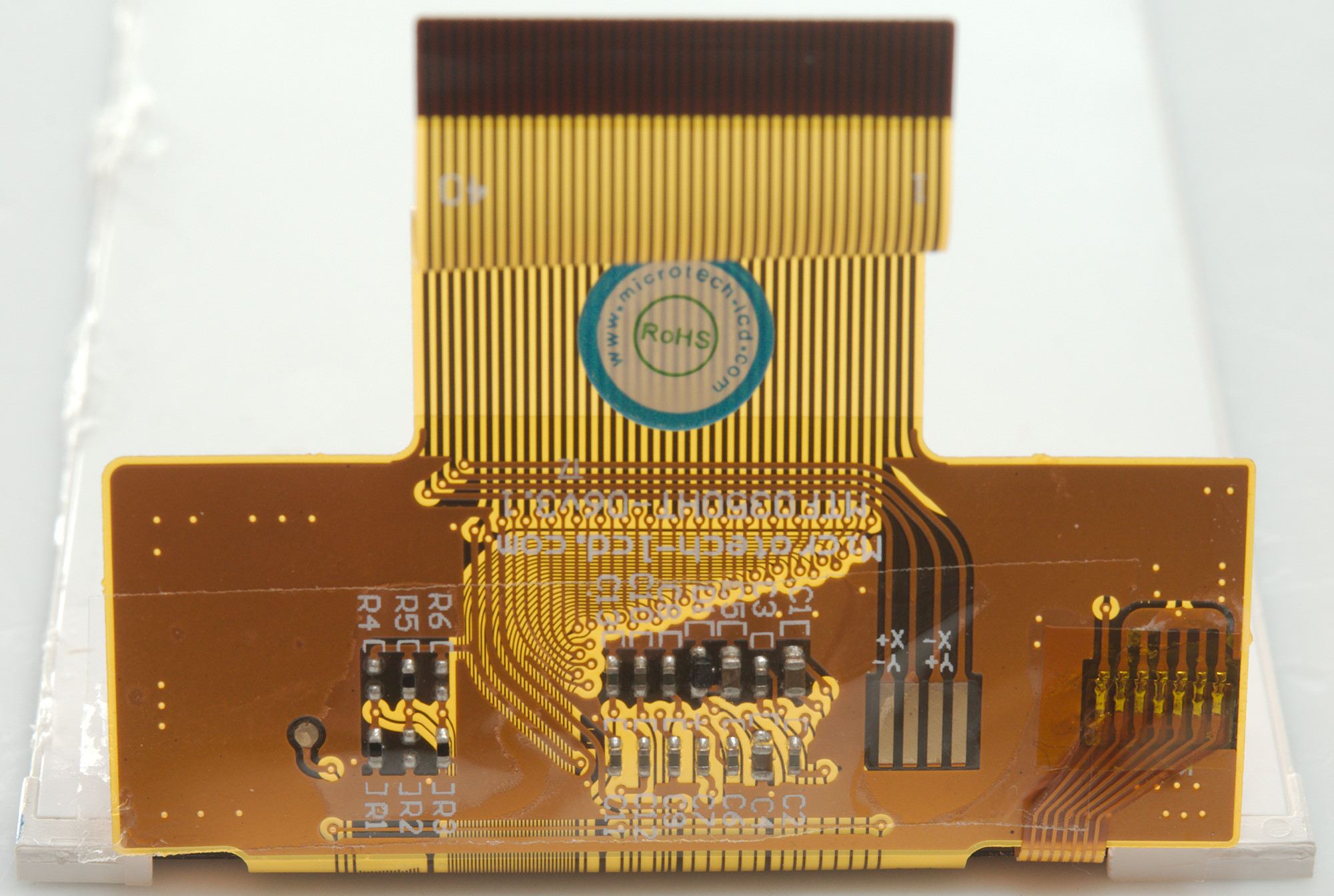
The display cable has some parts on it and there probably is a controller in the display. I wonder if the +X -X +Y -Y means it is a touchscreen.
The touch input is lifted up to the cover with some connections.


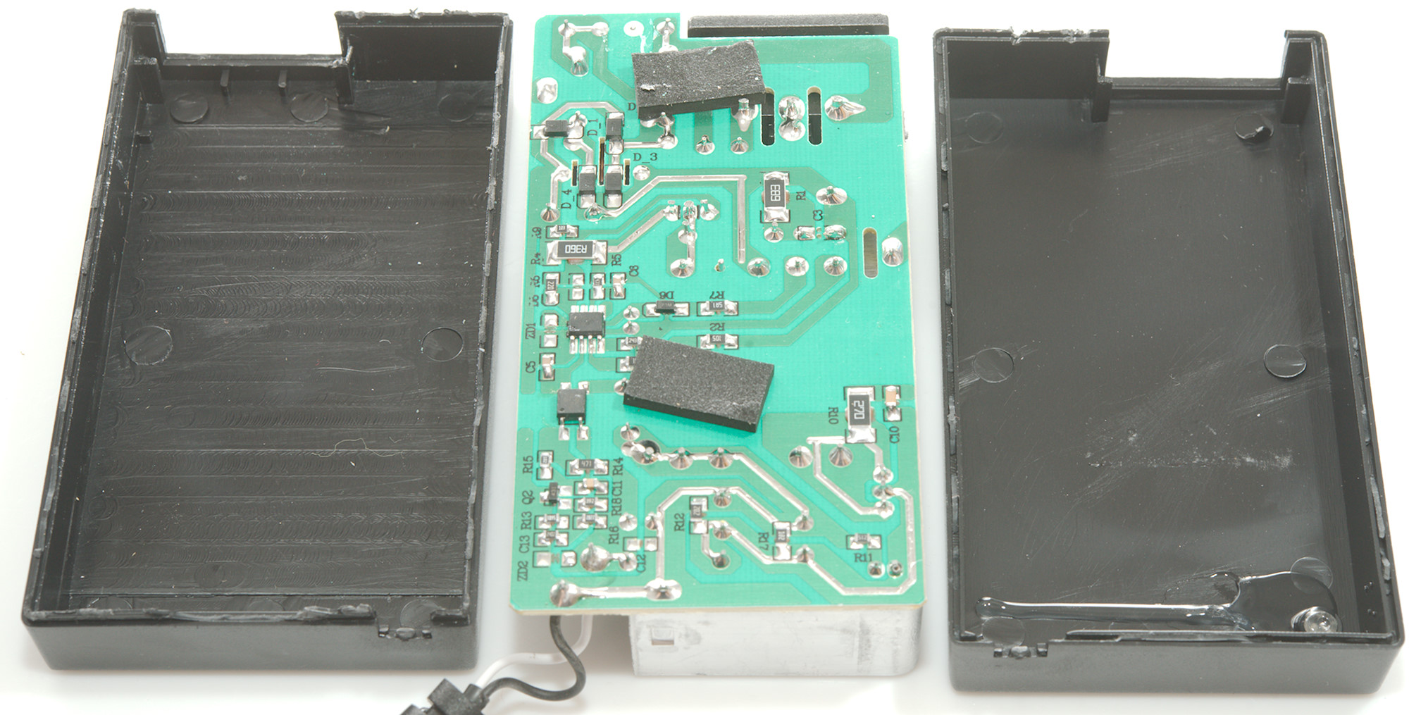
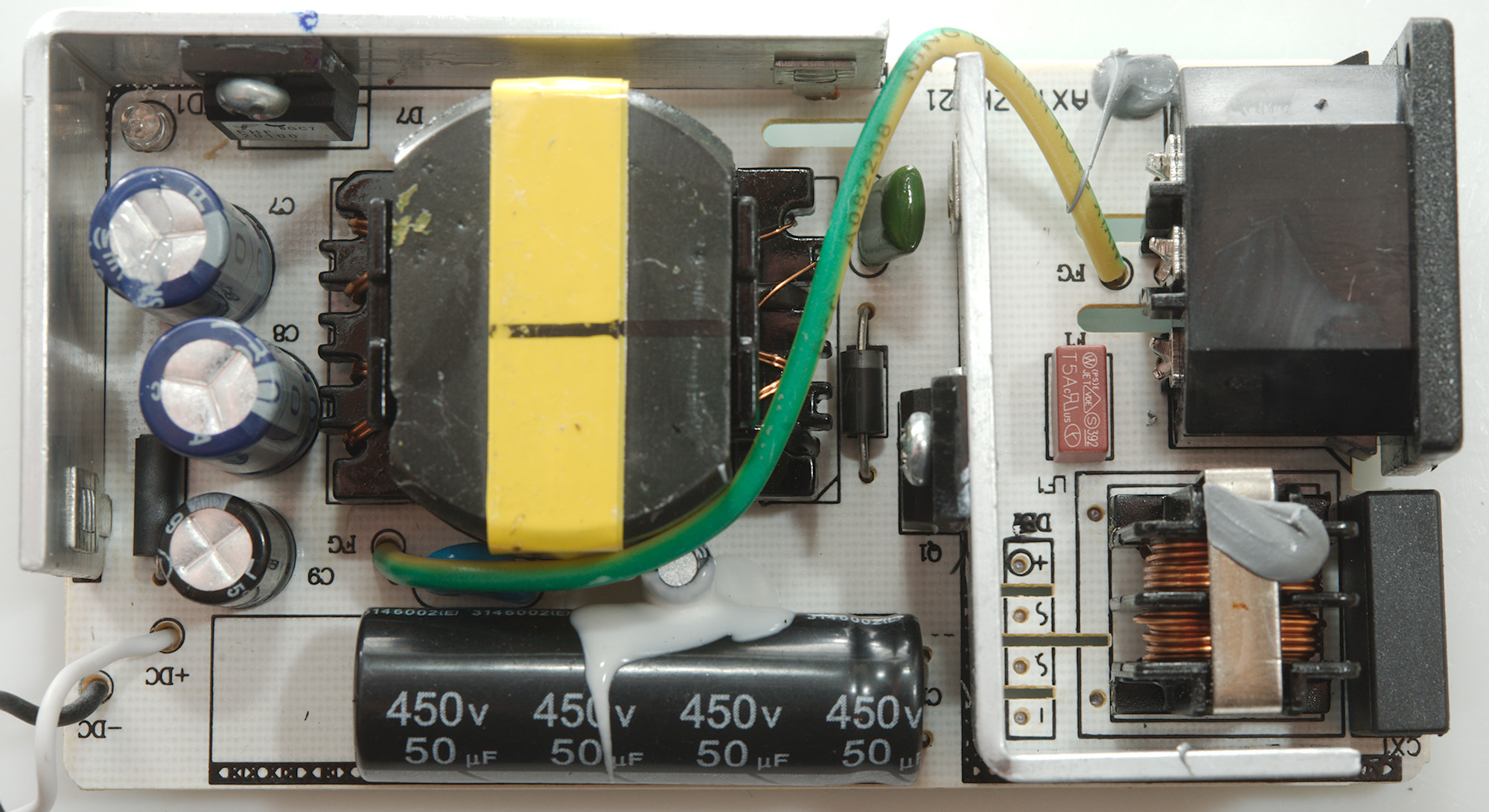
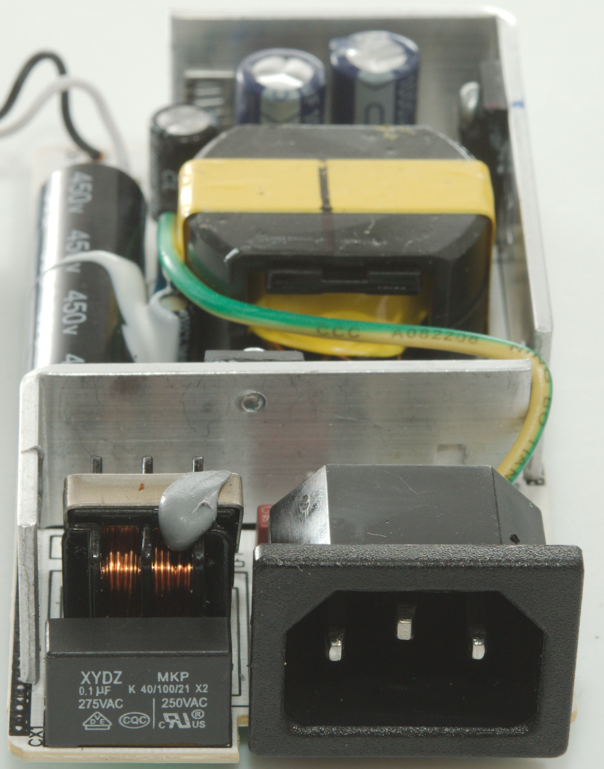
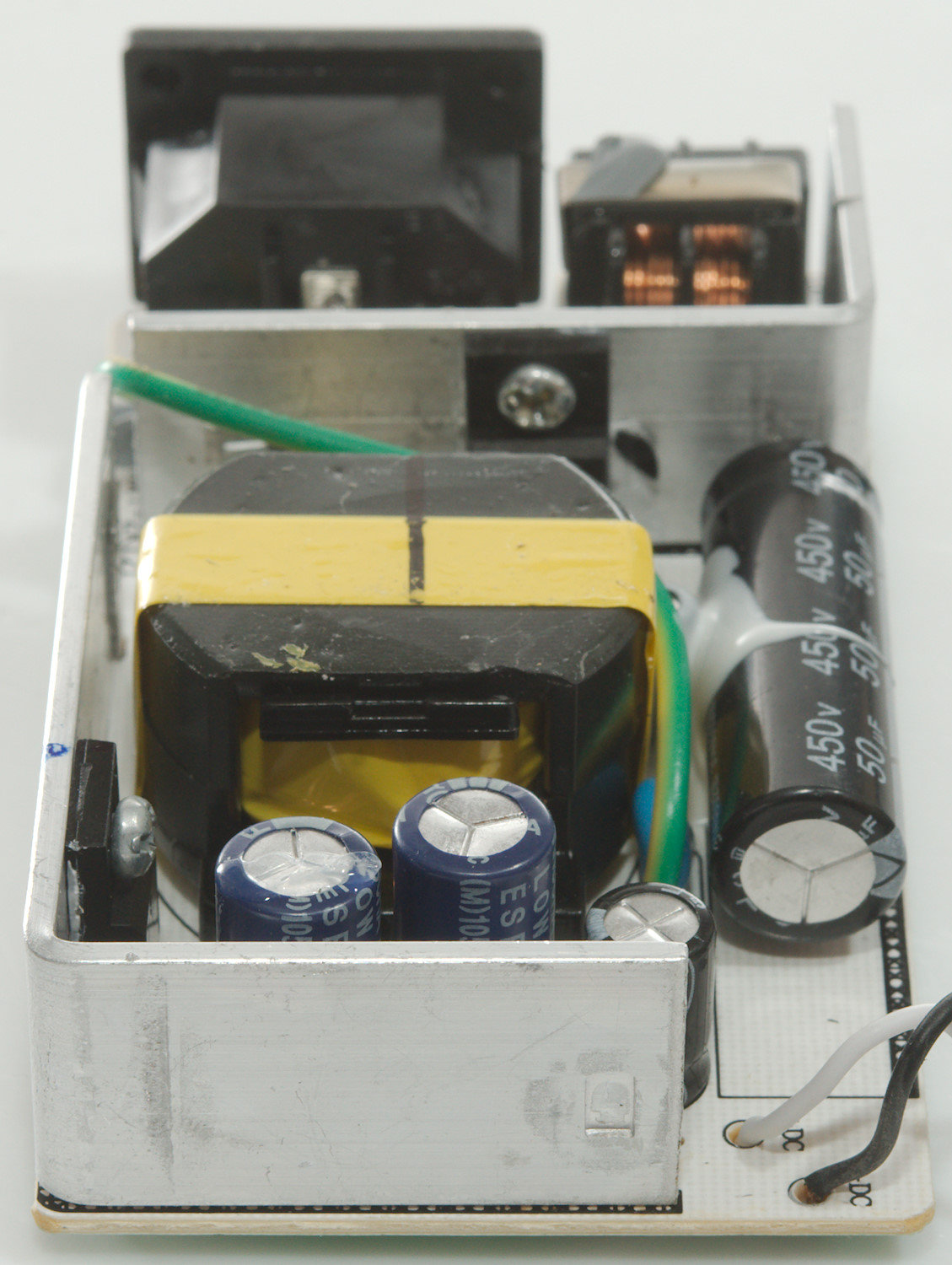
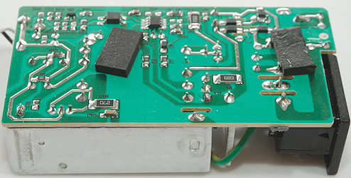
The power supply needed some pressure in my vice, then the seam cracked enough that I could break it apart.
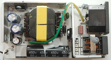
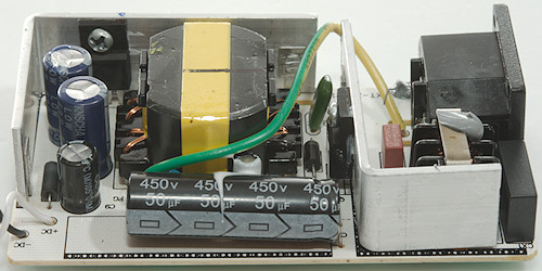
This side has a fuse, a common mode coil, the switcher transistor. Between mains and low volt side is the usual safety capacitor and on the low volt side is a rectifier diode, there is also a led next to the rectifier diode. The earth connection is routed from input to output with a yellow green wire, this means less strict safety requirements.
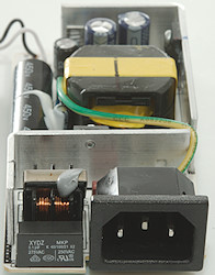
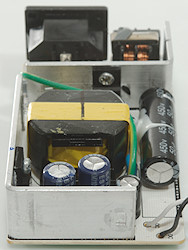
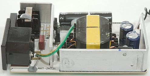
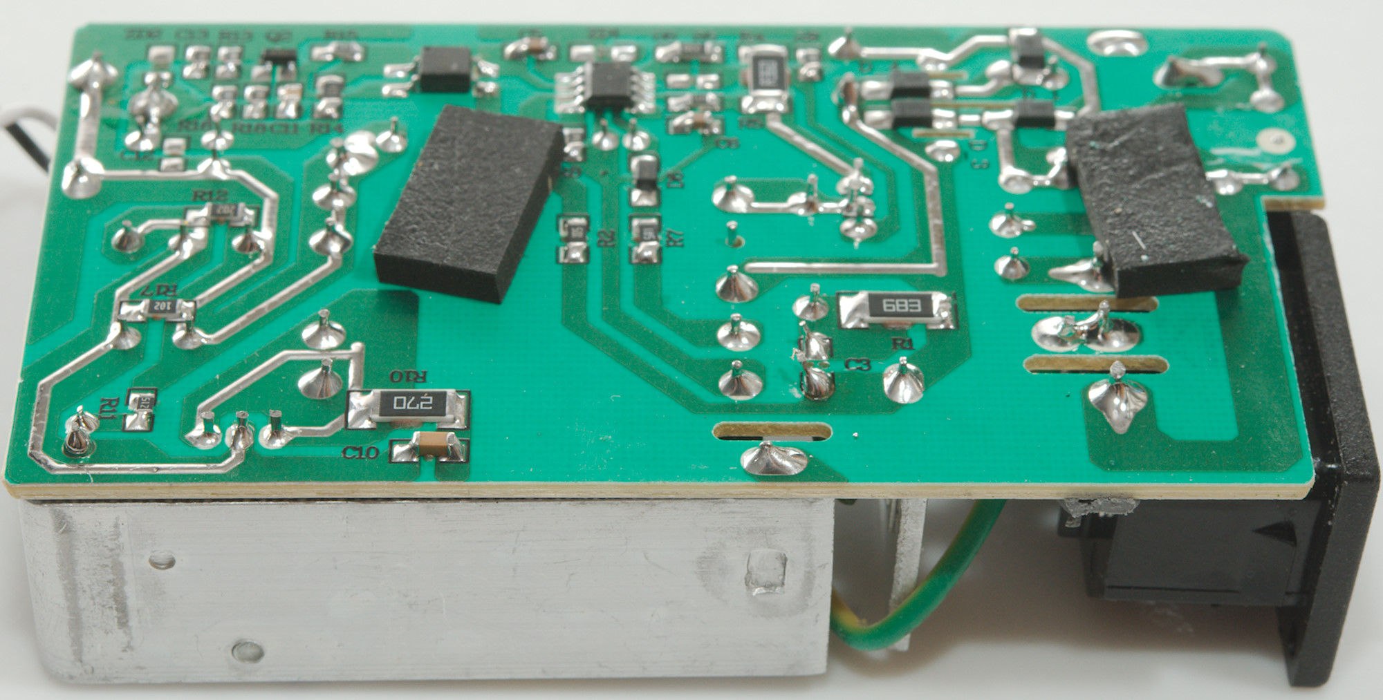
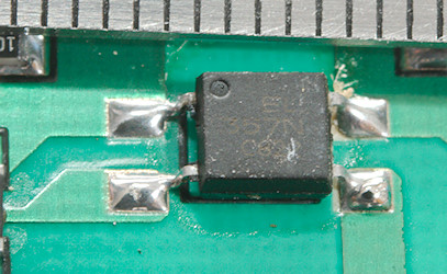
The mains is rectified with four diodes (D1..D4) in a bridge, the switcher controller OC2269AP) has opto feedback and a 431 on as reference on the low volt side.
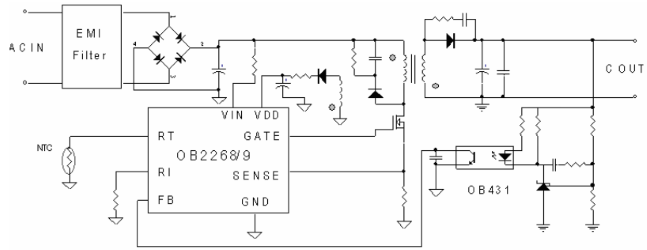
Here is the schematic from the datasheet, the supply is mostly following it.
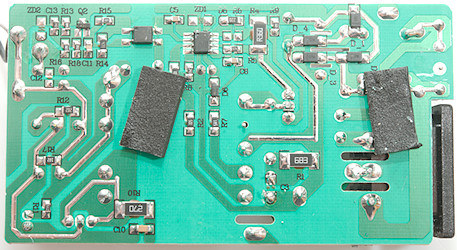
The distance between mains and low volt side is too short for class 2 equipment, but this is class 1 (With earth).
Testing with 2830 volt and 4242 volt between mains and low volt side, did not show any safety problems.
Conclusion
The Voltbot is a very powerful USB charger with four fast charge outputs and a screen that shows status. It can also be used as a power supply and it is possible to get a accessory kit for easier connections.
I am not very impressed with the user interface, the icons are hard to read and the buttons hard to use (They activate more than easily enough, but you always needs many keys in sequence). The Wifi access is easier to use, but again it may require too many touches to work and the connection is not very stable.
In the different access methods the options are not always called the same and there is also differences between what is possible.
As a lab power supply it is way to difficult to use and I would like independent channels.
As a charger it is good and to power a couple of devices it is also good, but I am missing some sort of safeguard, i.e. when a special purpose USB connector is removed it switches back to 5V output.
Notes
The charger was supplied by a reader for review.
Index of all tested USB power supplies/chargers
Read more about how I test USB power supplies/charger