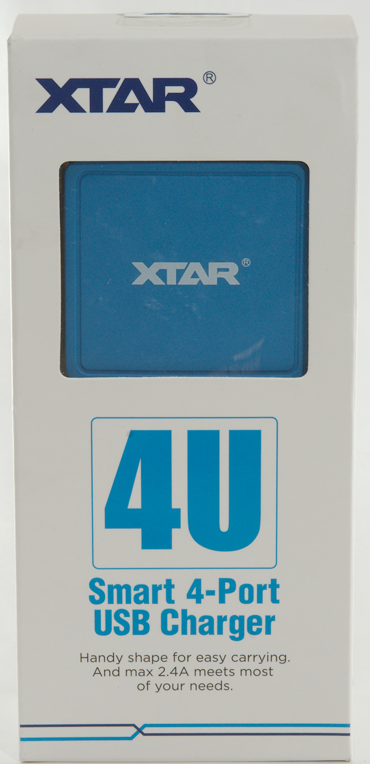
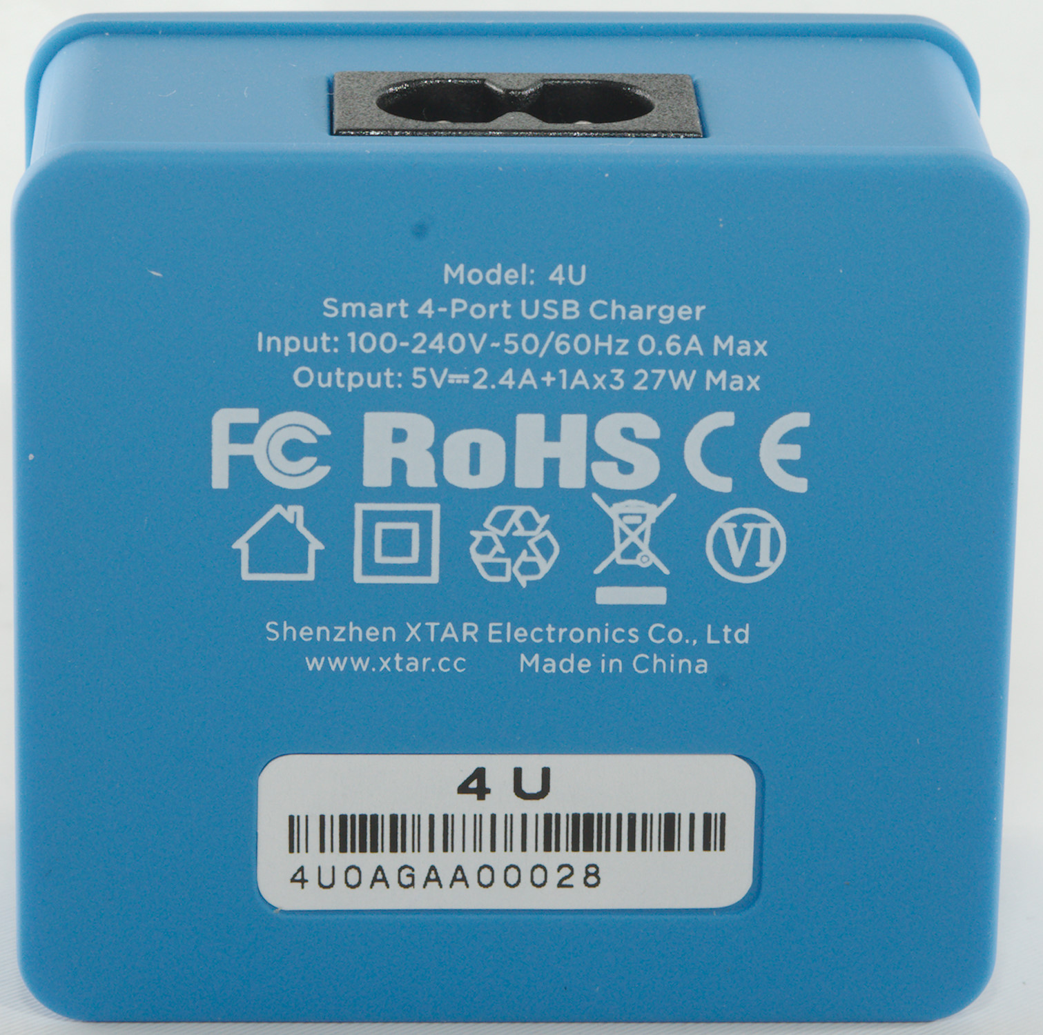
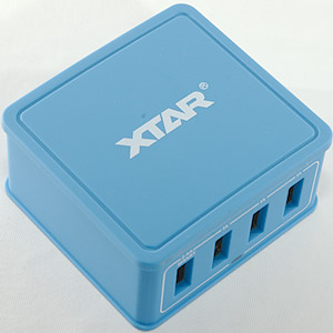
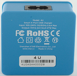
Xtar 4U Smart 4-Port USB charger
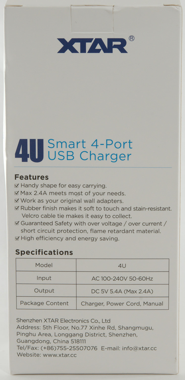
Official specifications:
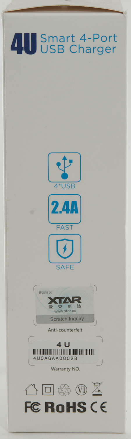
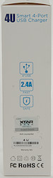
- Max 2.4A fast charging speed
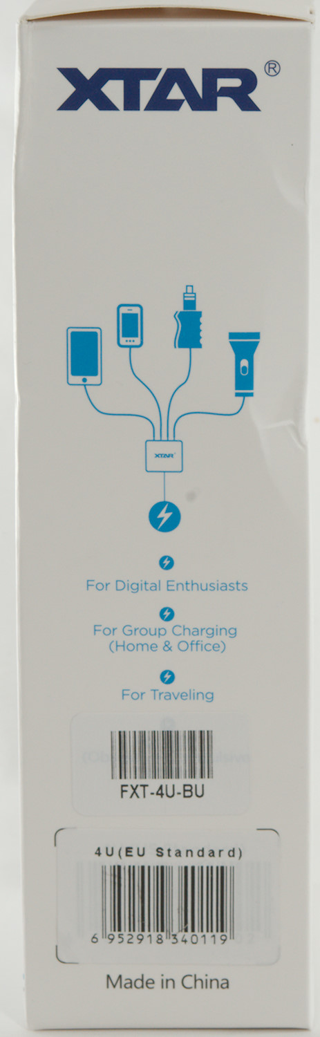
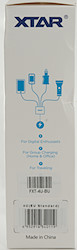
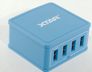
- Charge 4 USB devices, say goodbye to countless adapters
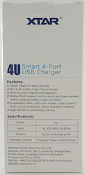
- High efficiency with US DOE VI standard
- Durable nickle-planted all-copper USB ports
- 100V-240V AC input, ideal for international travel
- Beautiful shape, delicate design, comes with different colors
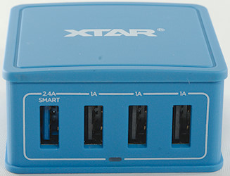
- Output voltage: 5 ~ 5.25V
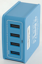
- Output current: 2.4A (USB1) / 1A (USB 2&3&4)
- Weight: 93g (3.28oz)
- Size: L62.5 x W55 X H28.3(mm)
I got it from a Ebay dealer: crodex.outdoor
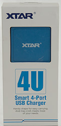
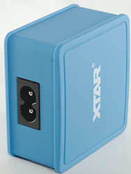
It arrived in a cardboard box with specifications on it.
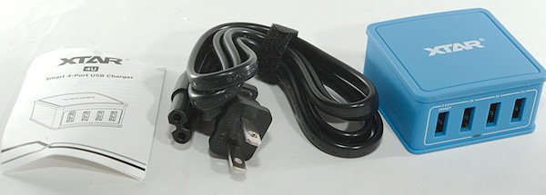
The contents was the charger, a mains cable and a instruction sheet.
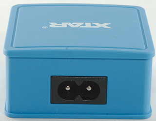
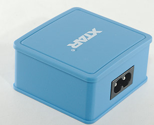
The window at the bottom is a blue led that will light up when power is connected.
Measurements
- Output 1 is auto code with DCP, Samsung and Apple2.4A
- Output 2-4 is usb charger (DCP)
- All outputs are in parallel
- Power consumption when idle is 0.15 watt
- Weight: 93.8g without accessories
- Size: 60 x 56 x 30.2mm
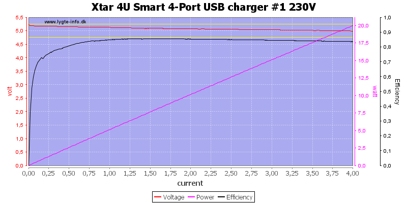
The first port could easily deliver 4A


All 4 ports could deliver over 4A, there is no individual overload protection on the ports.
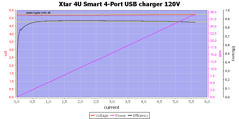
When run in parallel I could draw about 5.6A at 120VAC
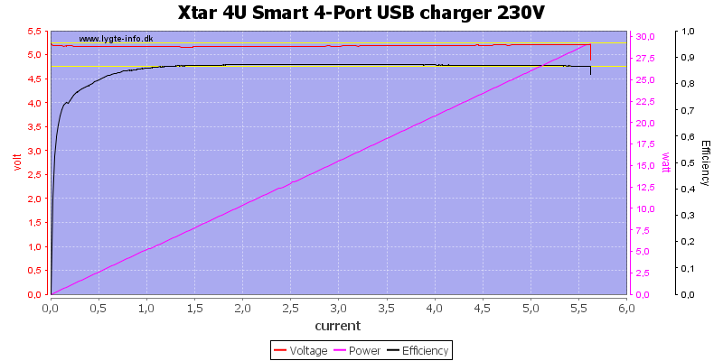
And the same at 230VAC
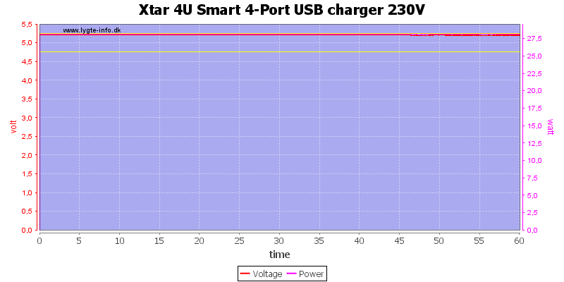
The charger could deliver 5.4A for one hour.
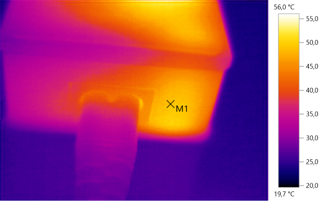
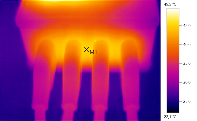
The temperature photos below are taken between 30 minutes and 60 minutes into the one hour test.
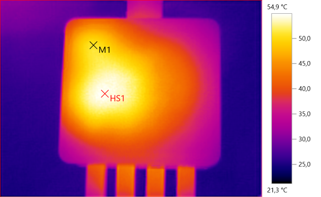
M1: 50.8°C, HS1: 54.9°C
HS1 is the transformer and M1 is the switcher transistor.
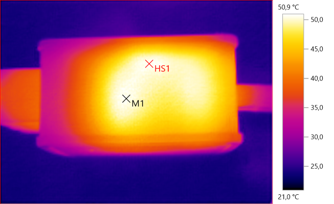
M1: 50.7°C, HS1: 50.9°C
M1 is the transformer.
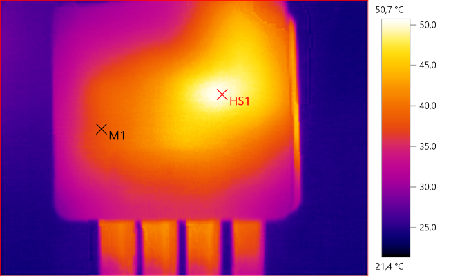
M1: 38.1°C, HS1: 50.7°C
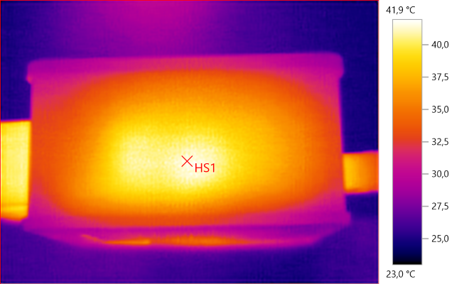
HS1: 41.9°C
M1: 48.6°C
M1: 44.9°C
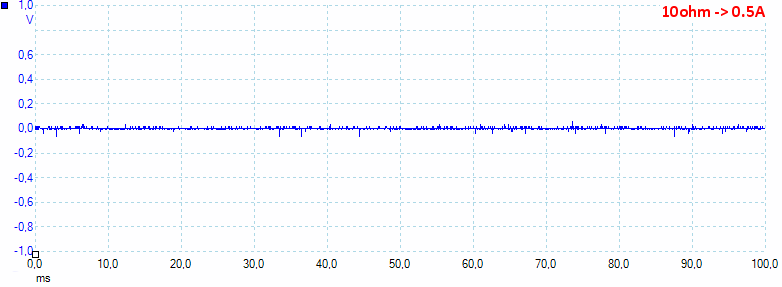
At 0.5A the noise is 6mV rms and 158mVpp
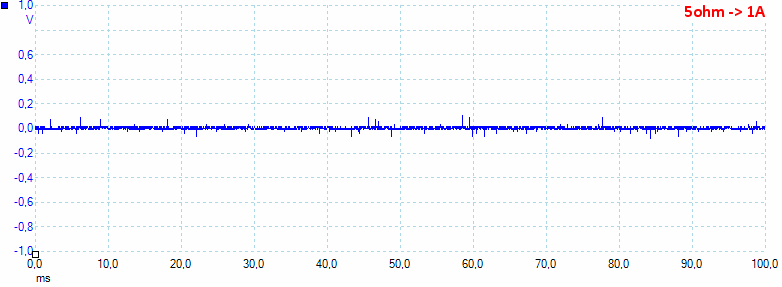
At 1A the noise is 15mV rms and 233mVpp
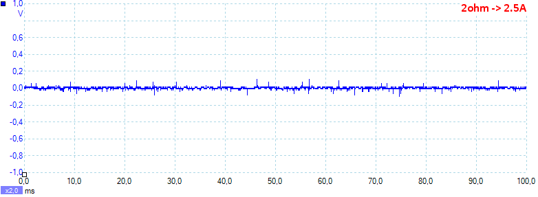
At 2.5A the noise is 18mV rms and 648mVpp.
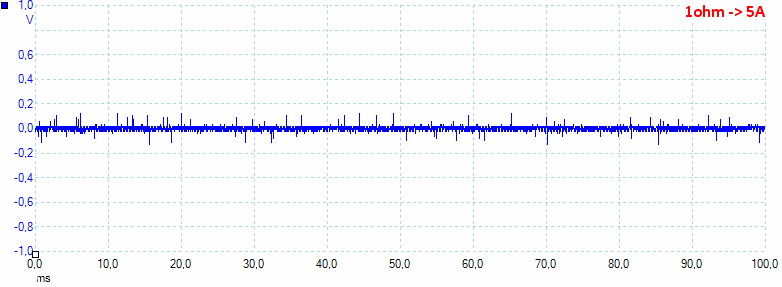
At 5A the noise is 34mV rms and 516mVpp.
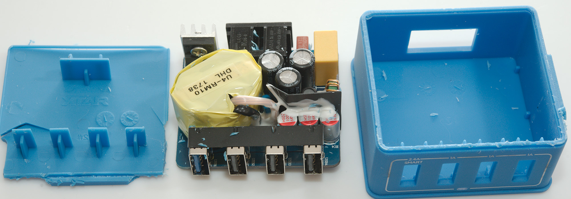
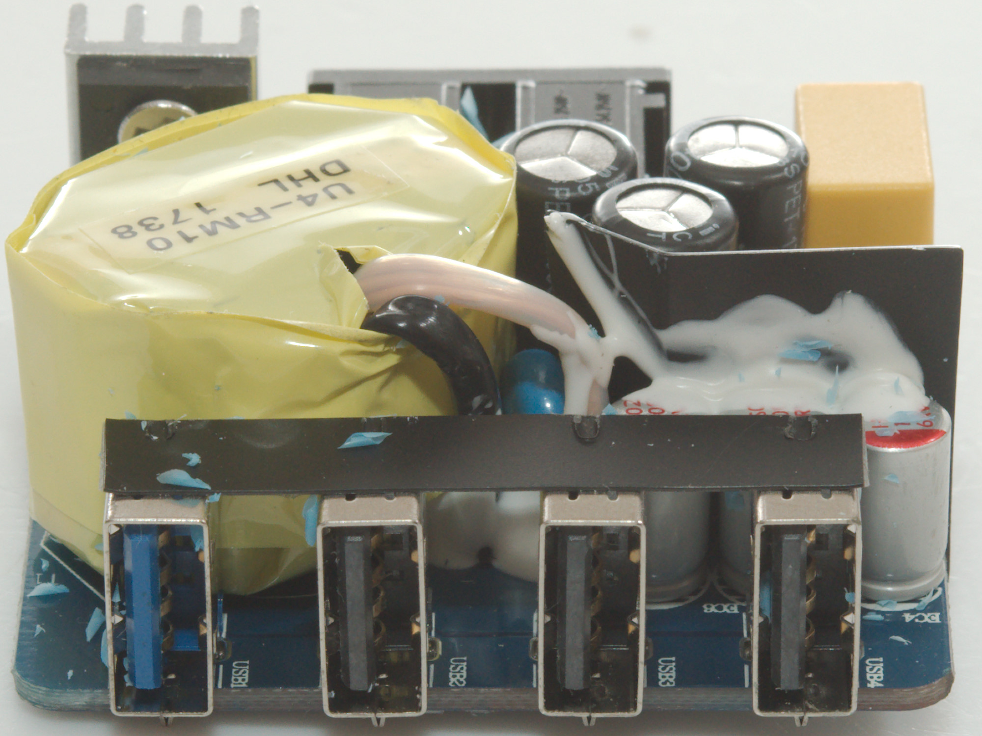
Tear down

I could not break this one open, the glue was fairly good and the plastic started cracking. Cutting worked fine.
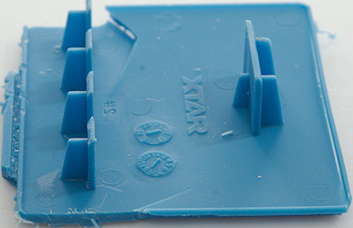
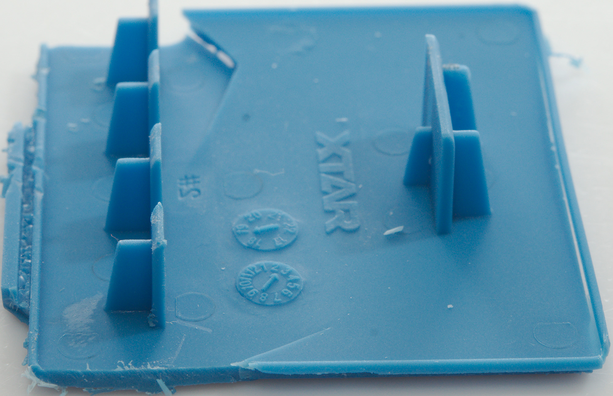
These pillars are used to keep the usb and mains connector in place, even if you are a bit hard on them when putting a plug in.

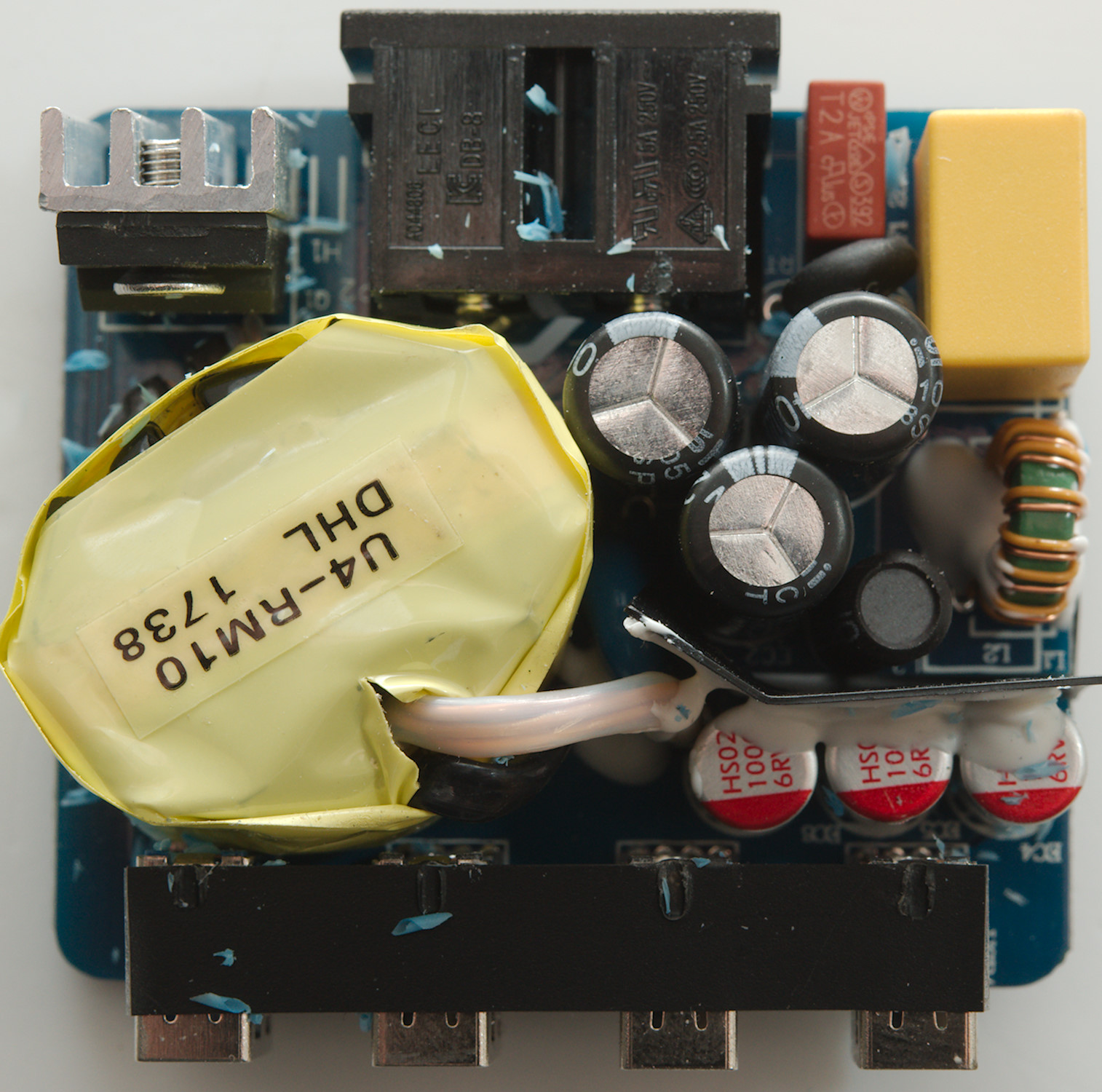
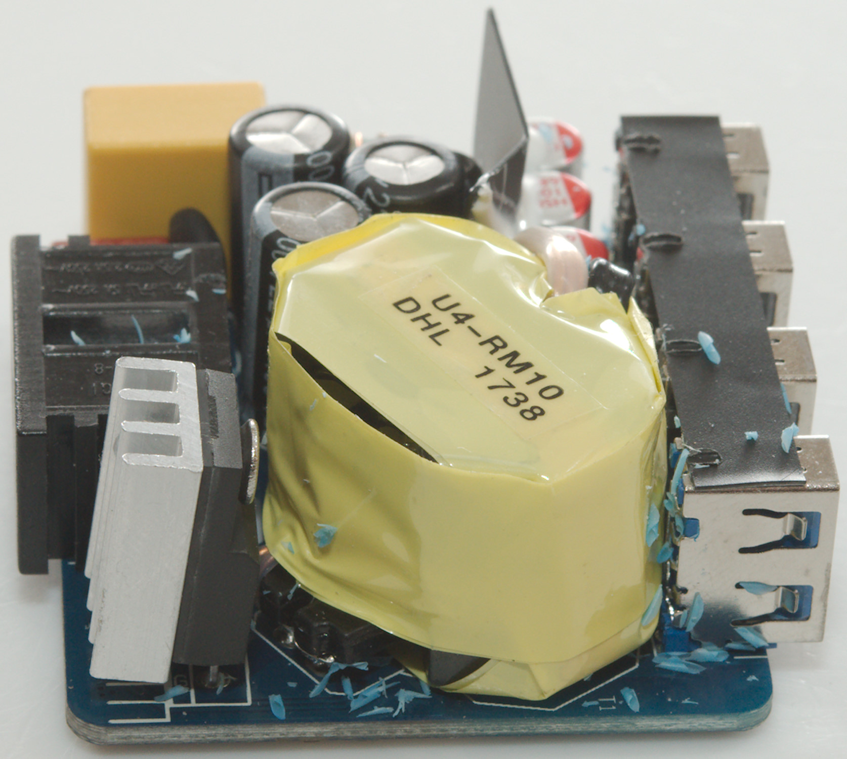
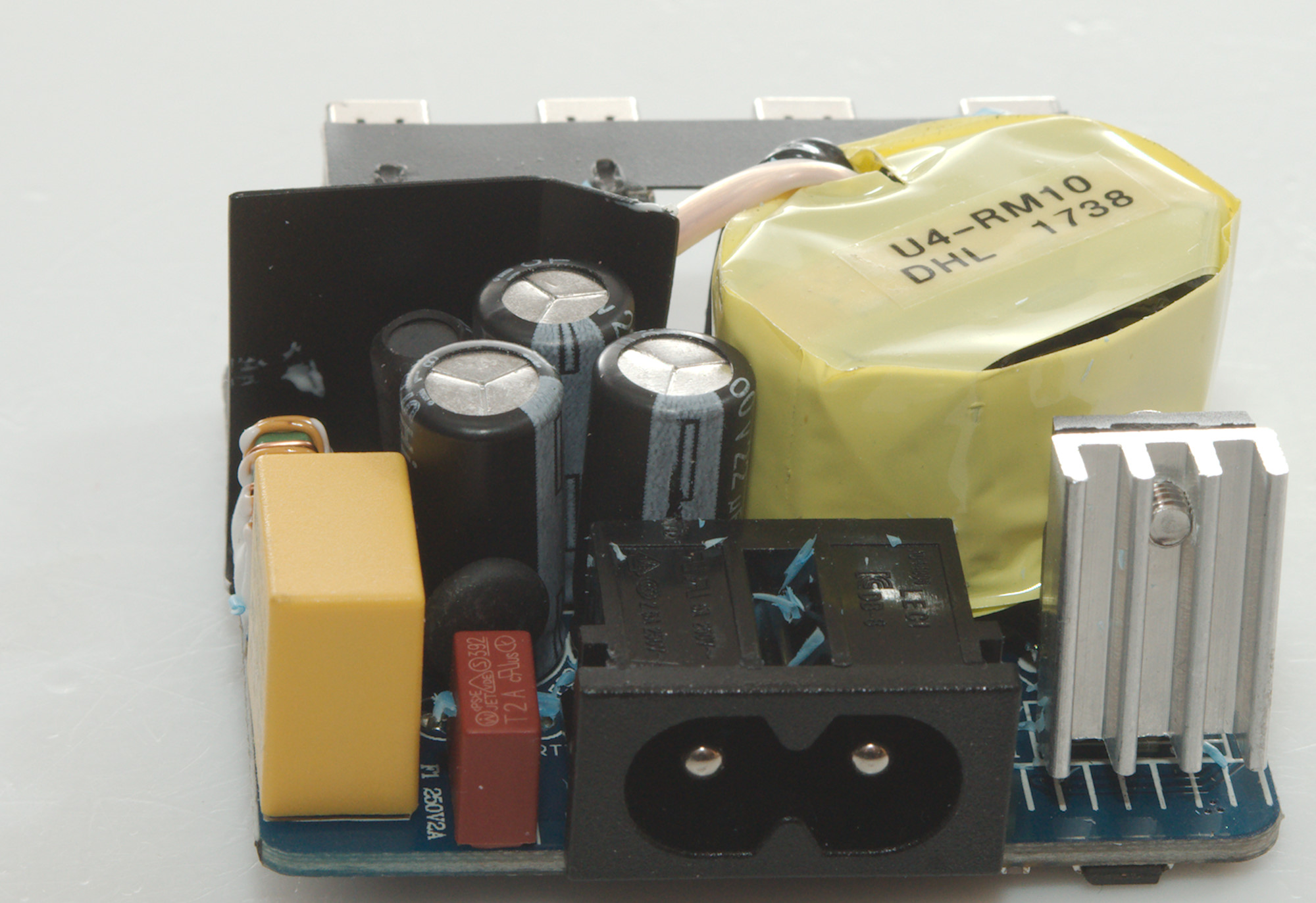
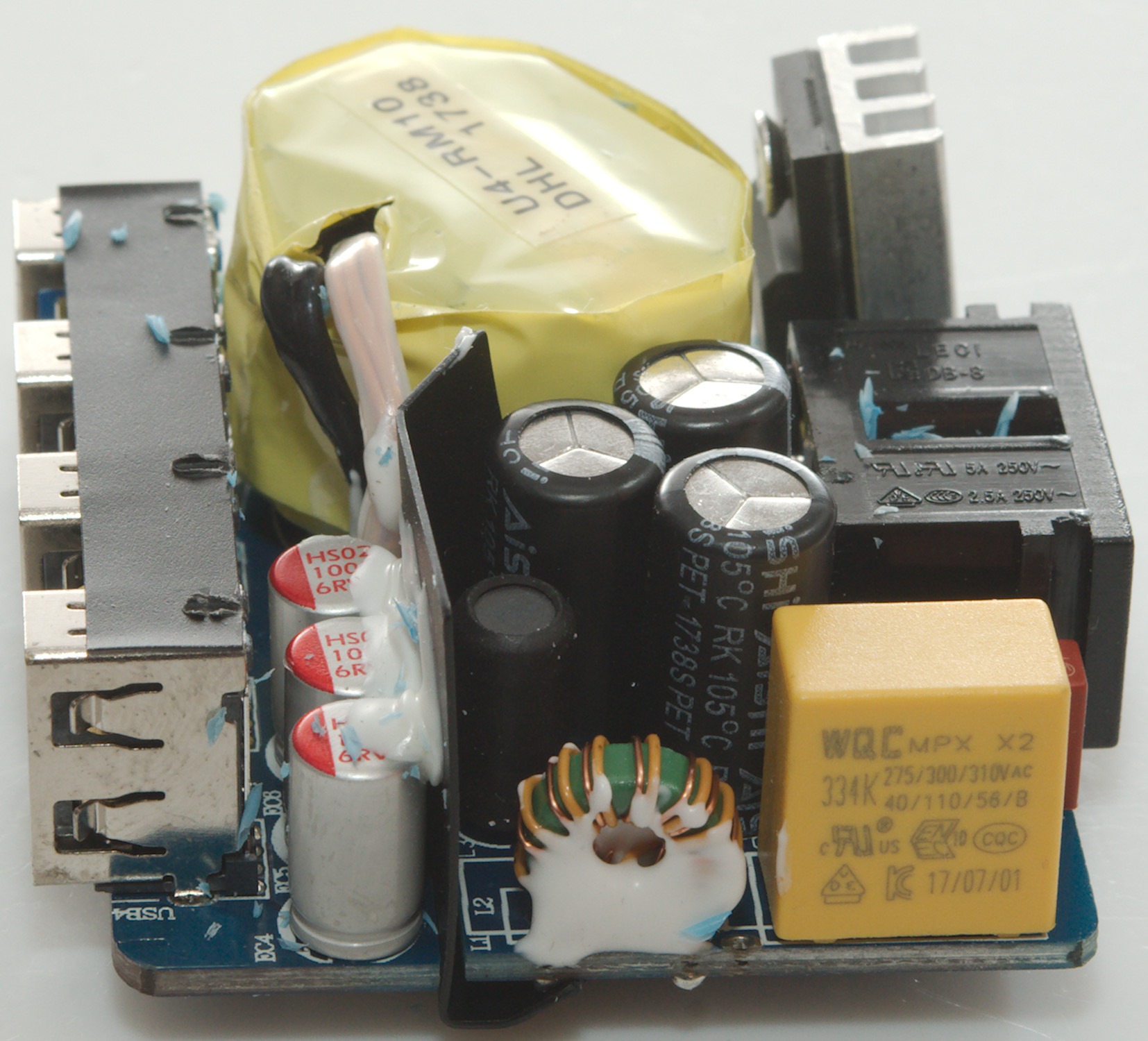
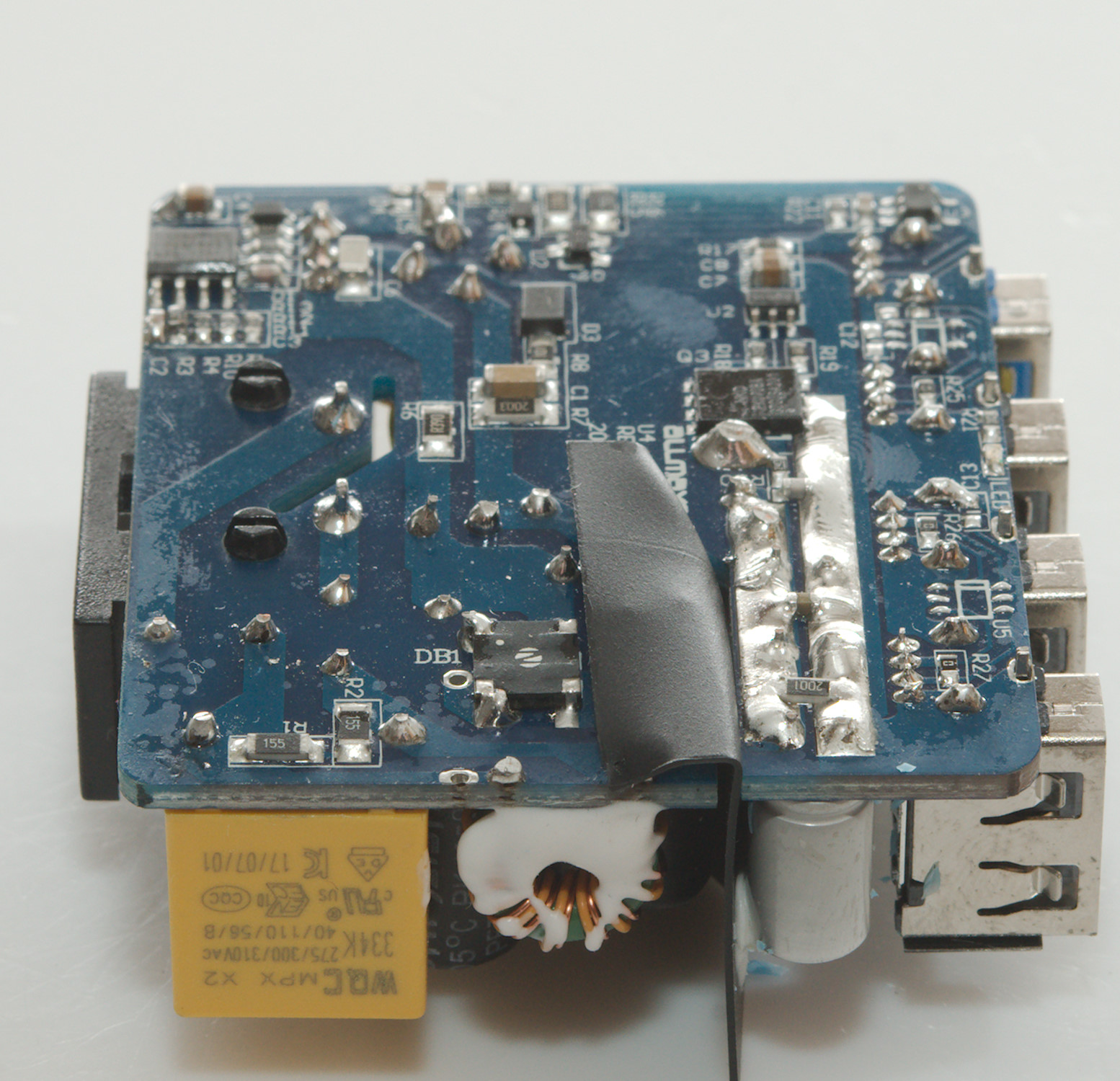
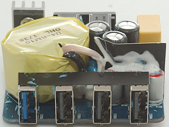
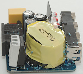
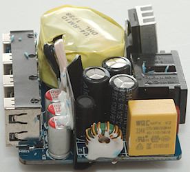
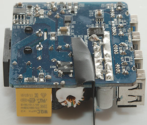
This is a very compact design, with a fuse (F1) and a inrush current limiter (RT: NTC) at the input, followed by a common mode coil (L1 & L2). There is also an inductor (L3) between some of the smoothing capacitors. On the other side of the mains connectors is the mains switcher transistor on a small heatsink. Beside the transformer, next to the black isolation is a safety capacitor.
The low volt side only has the capacitors and the usb connectors.
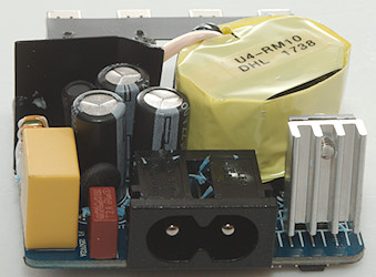
The mains switcher transistor on its heatsink.
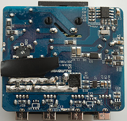
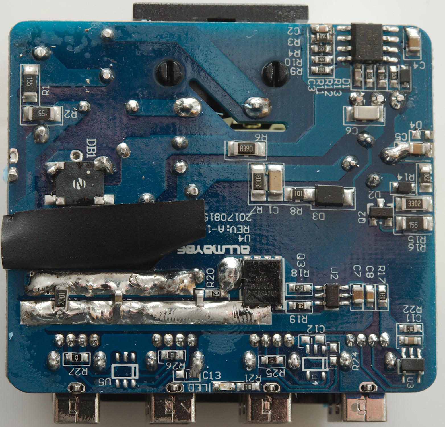
On this side are the chips and the bridge rectifier (DB1). The mains switcher is below the switcher transistor.
The low volt side has a power mos for rectification (Q3) controlled from a synchronous controller chip (U2). There is one auto coding chip (U3), but space for more (U4 & U5). The blue led (LED) is mounted on this side.
The black isolation sheet is very important to get enough isolation distance.

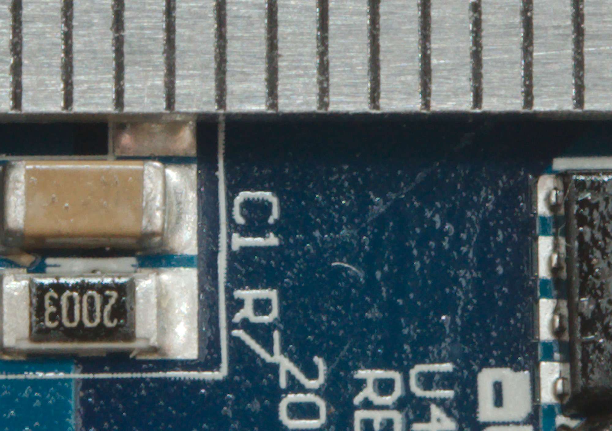
Safety distances looks fine.
Testing with 2830 volt and 4242 volt between mains and low volt side, did not show any safety problems.
Conclusion
This charger works fine and is safe. One auto coding port is a bit sparse, but then most devices knows standard usb coding and will charger at a decent speed on it. This means the charger is fine for one power hungry device and a couple of other devices (Usb powered battery chargers do usual not check coding and can be used on any port getting full power).
It is a good charger, but with some power limitations.
Notes
Index of all tested USB power supplies/chargers
Read more about how I test USB power supplies/charger
How does a usb charger work?