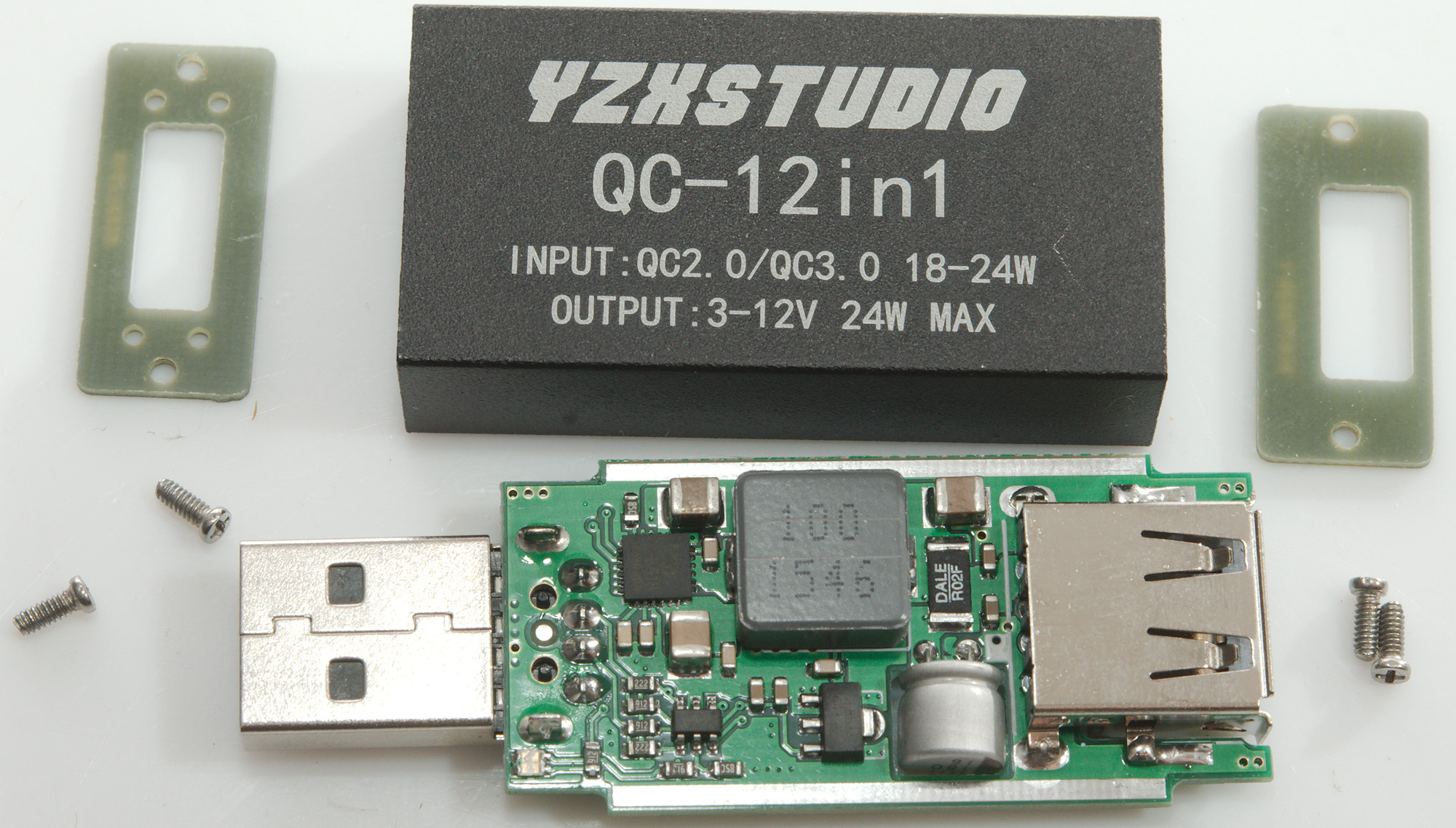
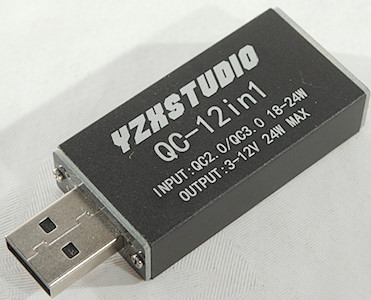
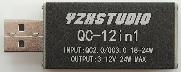
YZXStudio QC-12in1
Official specifications:
- Product Type: Flash Charger Adapters
- Brand: YZXstudio
- Depth: 11 mm
- Height: 45 mm
- Width: 24 mm
- Product Weight: 30 g
- Input: QC2.0/QC3.0 18-24W
- Output: 3-12V 24W Max
I got it from fasttech sku:9654019
The charger arrive in a envelope without any instructions or other accessories.
Measurements
- Use 12V input voltage, can be from a QC charger.
- Power consumption when idle is 2.4mA
- USB output is auto coding with: Apple 2.4A, Samsung, DCP, QC3, Samsung-AFC, Huawei-FCP, Huawei-SCP, PE1.1, PE2.0
- Minimum QC3 voltage is 3.63V
- Weight: 19.5g
- Size: 62.1 x 23.9 x 10.9mm
Test with Blitzwold BW-S9 usb charger
This charger can deliver slightly above 20W before the output voltage drops at 12V.
There is cable compensation.
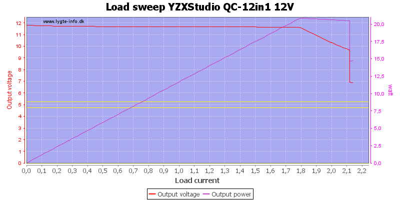
Comparing these curves to the ones below shows that the QC charger limits the power, not this device.
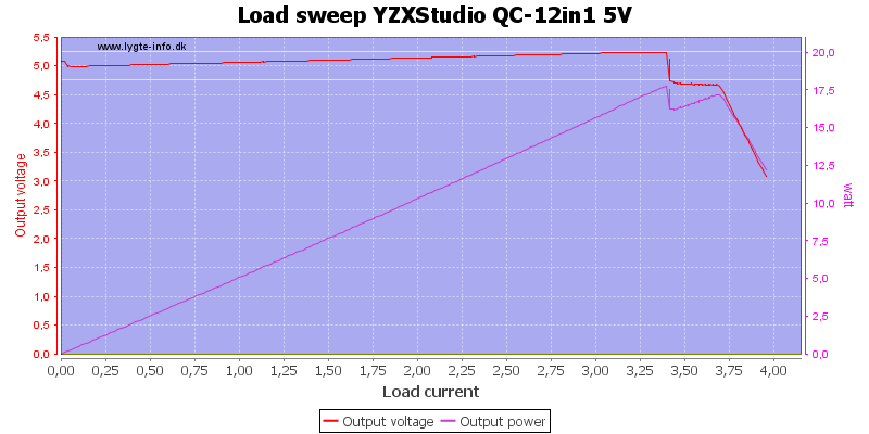
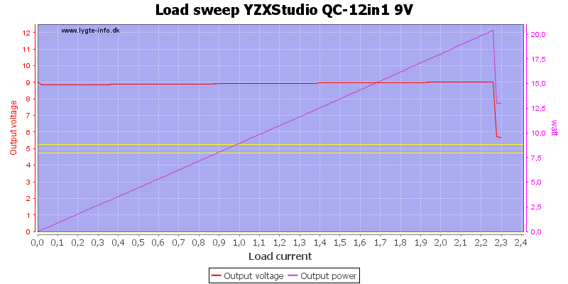
Test with power supply
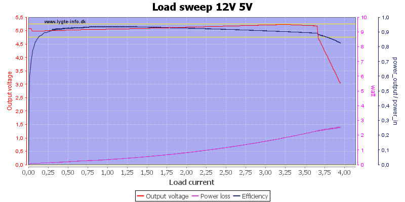
At 5V the output is limited to about 3.6A and there is some cable compensation. Efficiency is above 90% most of the time.
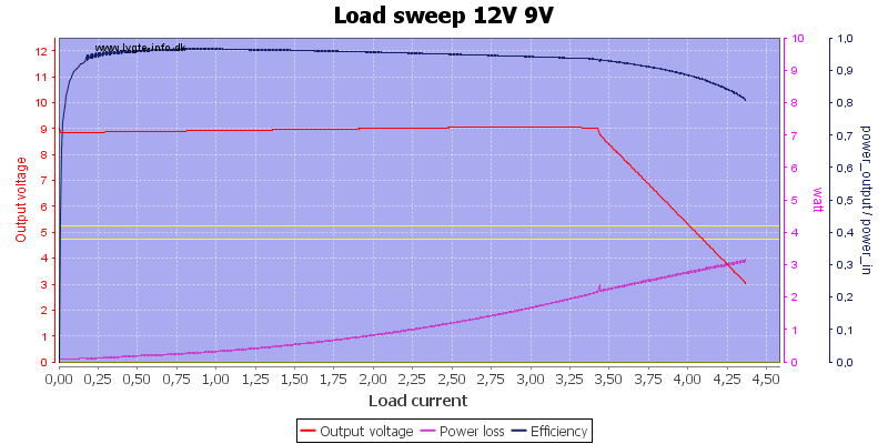
At 9V the maximum current is about 3.4A and there is also cable compensation here and even better efficiency.
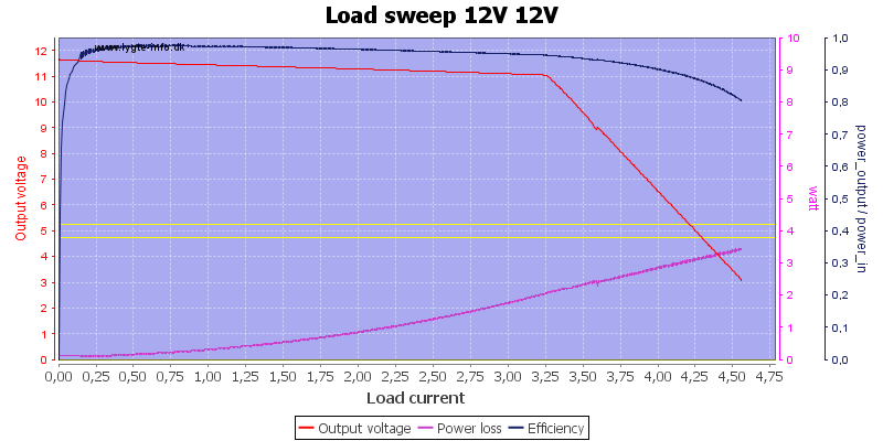
At 12V the current is limited to 3.2A and the cable compensation do not work, due to the limited input voltage.
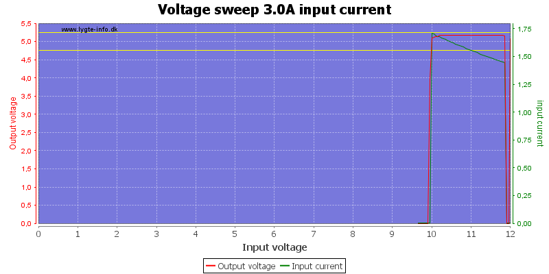
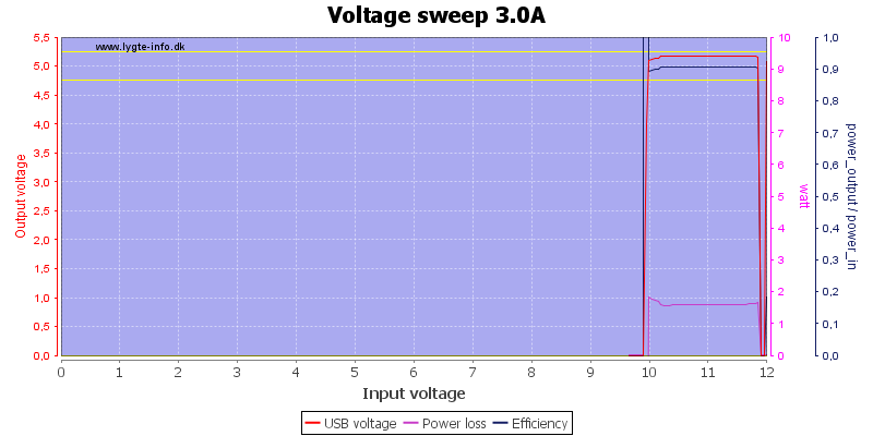
The device shuts down at around 10V input.
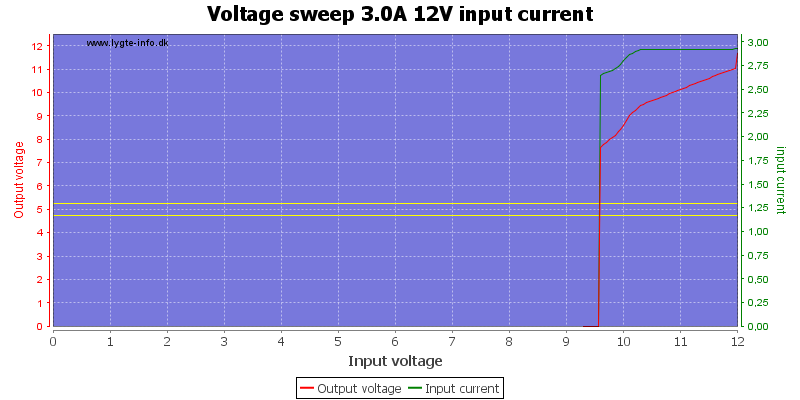
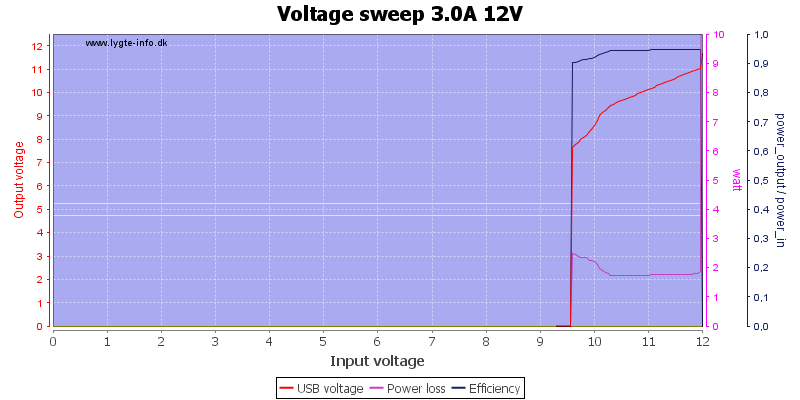
When 12V output is selected it will drop some before the device shuts down.
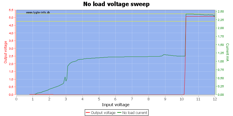
The input current is fairly constant until the device shuts down.
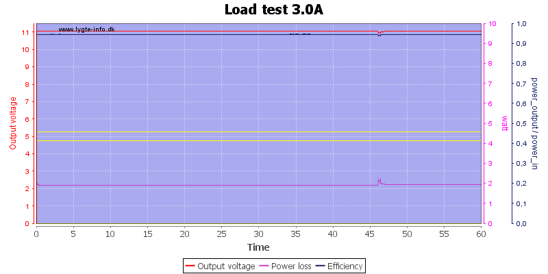
There was no problem running 1 hour with 3A load at 12V.
The temperature photos below are taken between 30 minutes and 60 minutes into the one hour test.
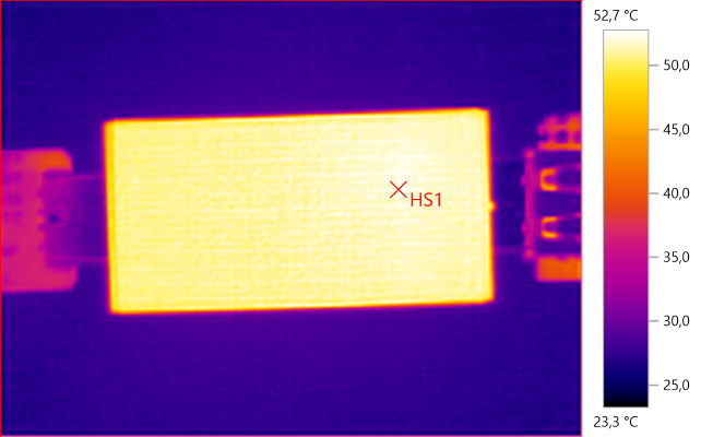
HS1: 52.7°C
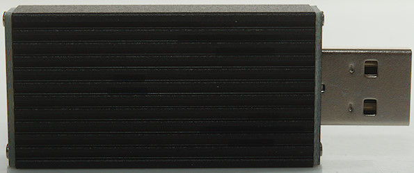
Being a aluminium enclosure the outside has nearly constant temperature all around.
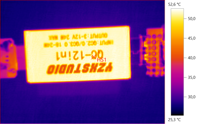
HS1: 52.6°C
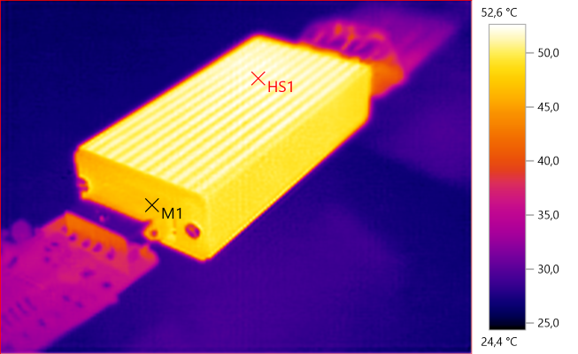
M1: 46.8°C, HS1: 52.6°C
The ends are made from circuit board and is considerable cooler.
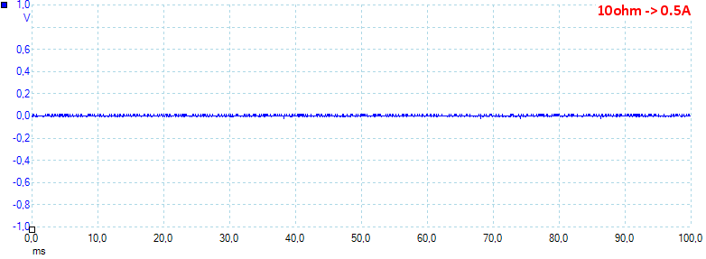
At 0.5A the noise is 10mV rms and 141mVpp.
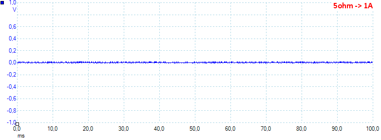
At 1A the noise is 5mV rms and 82mVpp.
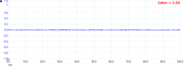
At 2.5A the noise is 6mV rms and 64mVpp.
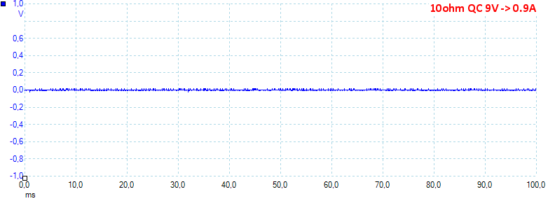
At 0.5A the noise is 5mV rms and 68mVpp.
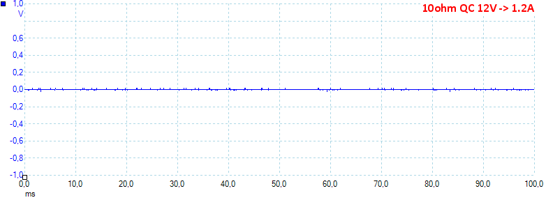
At 0.5A the noise is 5mV rms and 65mVpp, all very low noise values.
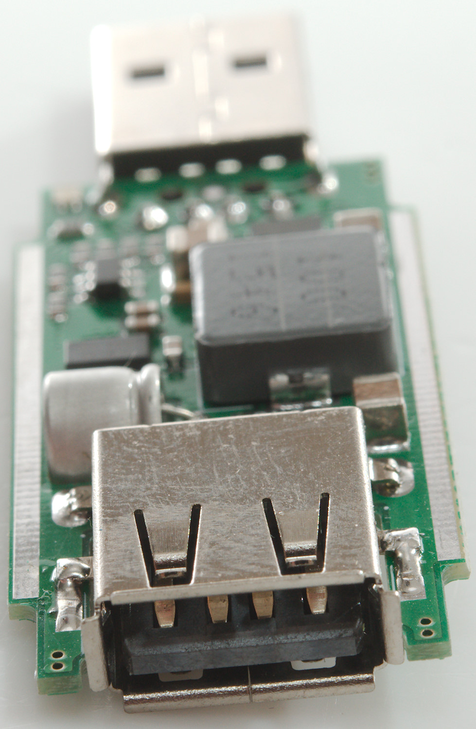
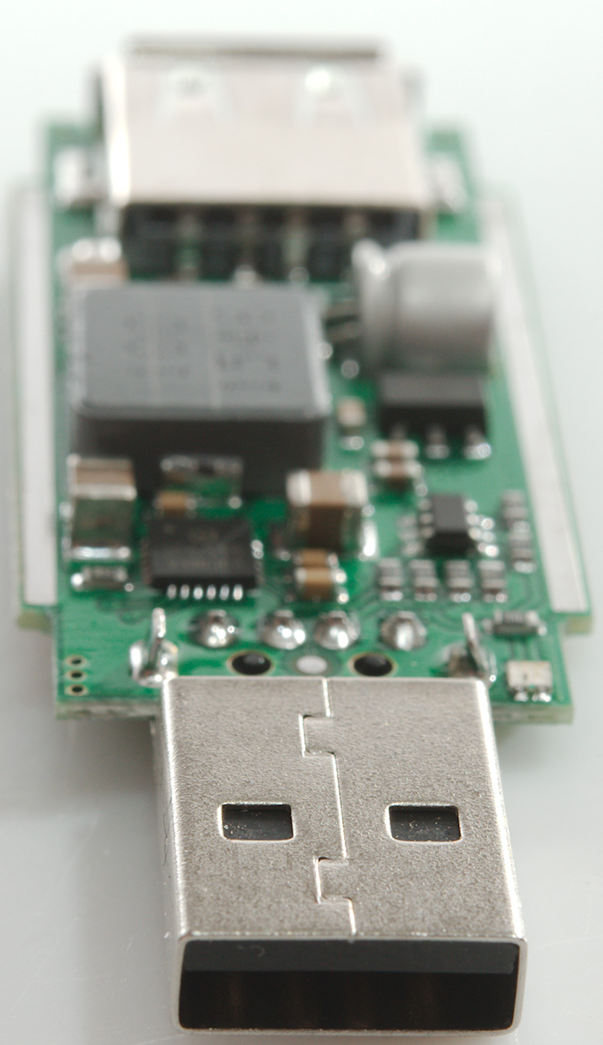
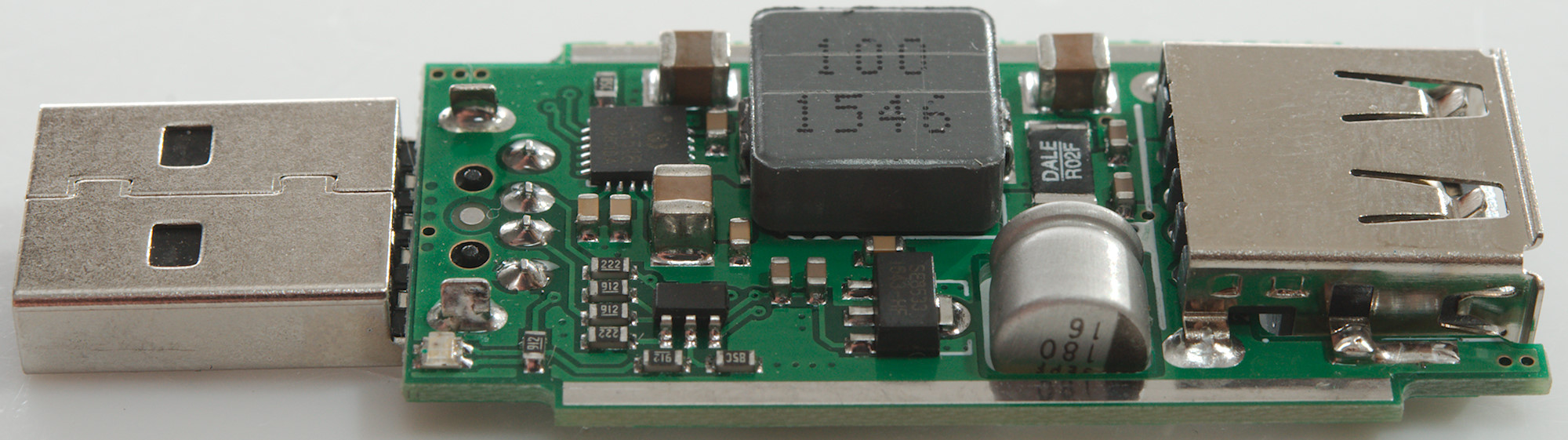
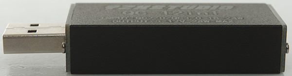
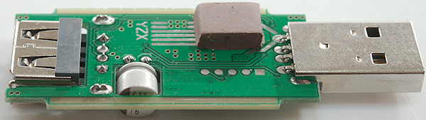
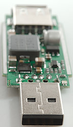
Tear down

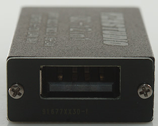
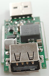
It was easy to open with four small screws. The small round holes at one end is for a led (One led, but the cover can be mounted either way around).
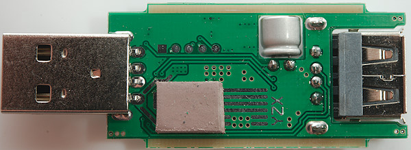
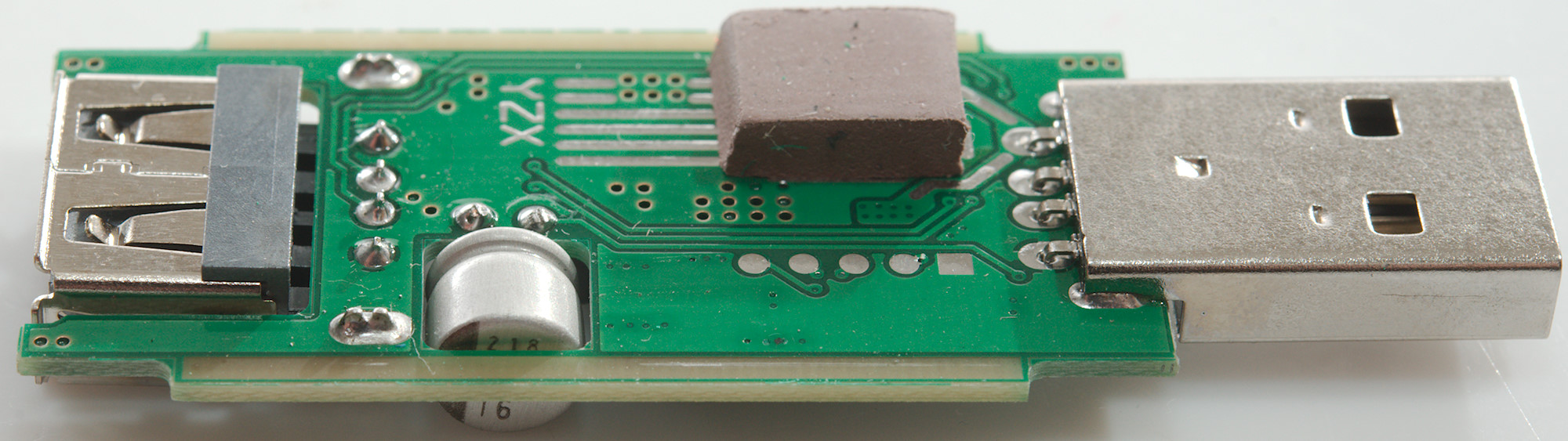
On this side is a capacitor and some heat transfer rubber. The capacitor is on the output side.
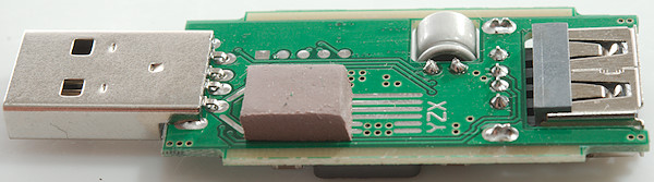
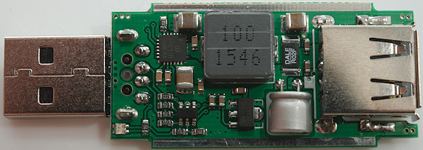
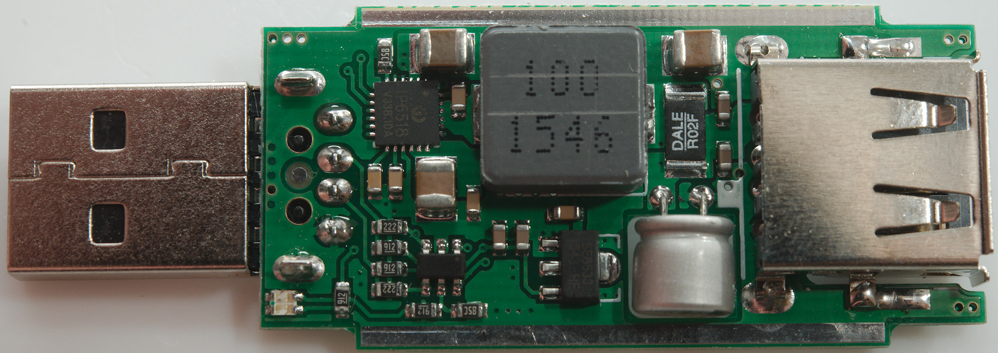
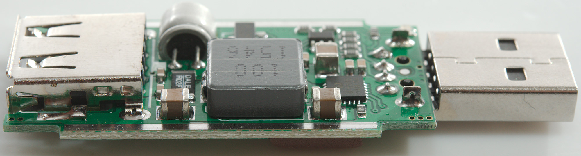
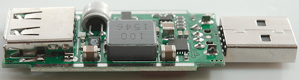
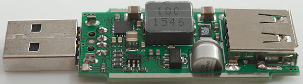
All parts are mounted on this side. There is a 6 pin chip, probably microprocessor, to trigger the 12V QC from the input connector and control at least part of the led. Next to it is a voltage regulator (SE8533: 3.3V). The output controller is a USB PD controller (IP6518), it supports: DCP/QC2.0/QC3.0/PE+1.1/PE2.0/FCP/AFC/SFCP/SCP/USB PD and is also the switching regulator. The PD function is obvious not used here.
Conclusion
This device can secure that any Quick Charger will support just about any fast charge protocol. I do not know how useful this is, normally I would prefer to get a charger with native support for the fast charge protocol that is needed.
The device works fine and with good efficiency.
Notes
Review of Blitzwold BW-S9 usb charger
Read more about how I test USB power supplies/charger
Compare car chargers and other DC supplied chargers