4 port multi charger
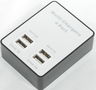
Official specifications:
- Form Color: White + Black
- Material: ABS
- Indicator Light: No
- Port Number: 4
- Spacing: 0.5A / 1A / 2A
- With Switch Control: No
- Interface: USB 2.0
- Transmission Rate: 480 Mbps (Data, from a charger?)
- Powered By: AC Charger (No, directly from mains)
- Other Features: Voltage: 110~250V; Output:5V
- Dimensions: 3.15 in x 2.44 in x 1.02 in (8.0 cm x 6.2 cm x 2.6 cm)
- Weight: 2.65 oz (75 g)
I got it from DX sku:844409927 (I do not believe they have it anymore).
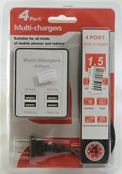
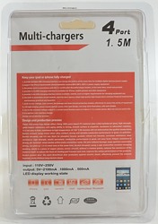
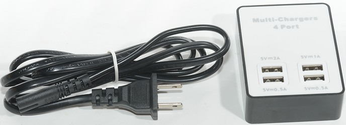
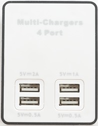
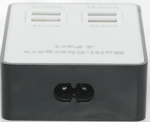
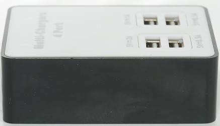
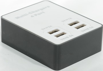
Measurements
- Power consumption when idle is 0.12 watt
- Has a blue led behind the usb connectors
- All Usb output is coded as Apple 2.1A
- All usb outputs are in parallel.
- Size: 80.3mm x 62.5mm x 26.2mm
- Weight (Without accessories or mains cable): 75.4g
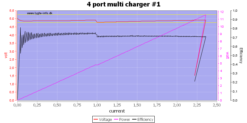
The 2A port can deliver about 2.3A, this looks fine enough.
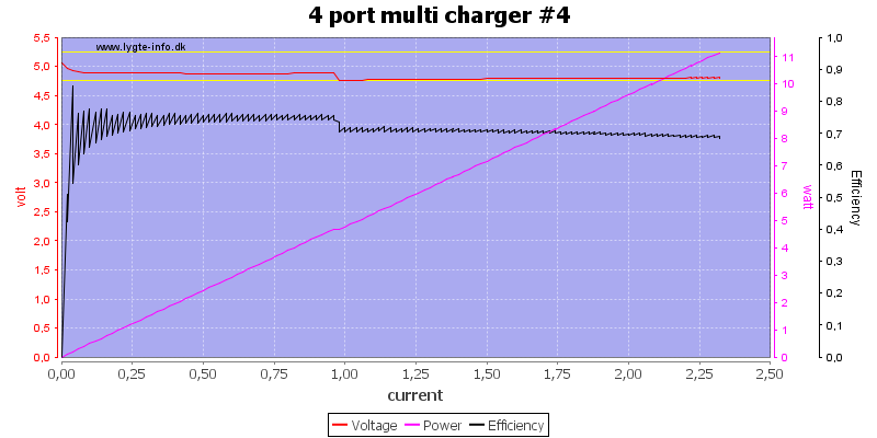
The 0.5A port can also deliver 2.3A?
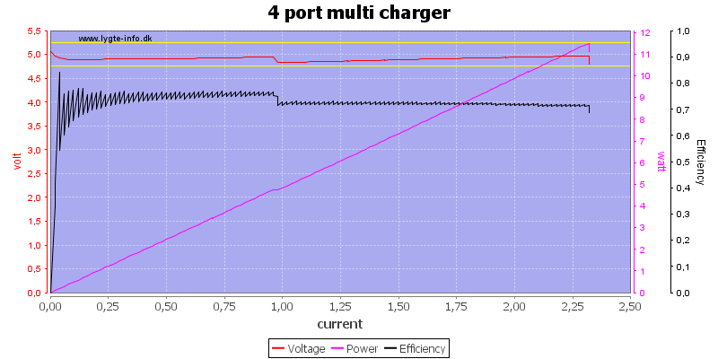
Running all port in parallel (Total marked current is 4A) can also deliver 2.3A, this is not very impressive.
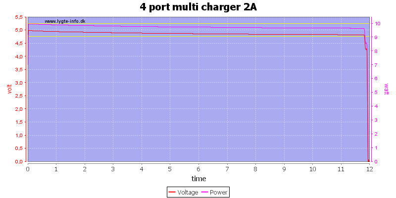
First try is a 2A load test, it could do that for 12 minutes, hardly enough time to charge a single pad.
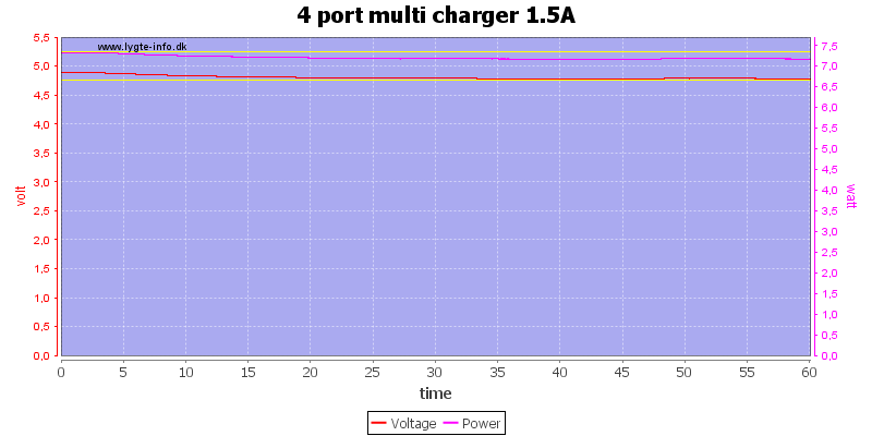
At 1.5A it works better, there I could run for one hour.
The temperature photos below are taken between 30 minutes and 60 minutes into the one hour test.
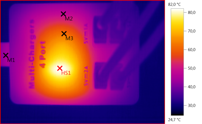
M1: 44,0°C, M2: 48,6°C, M3: 61,8°C, HS1: 82,0°C
HS1 is the transformer.
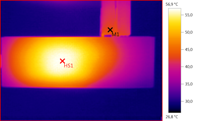
M1: 43,0°C, HS1: 56,9°C
HS1 is again the transformer, but probably with some help from the two rectifier diodes.
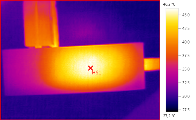
HS1: 46,2°C
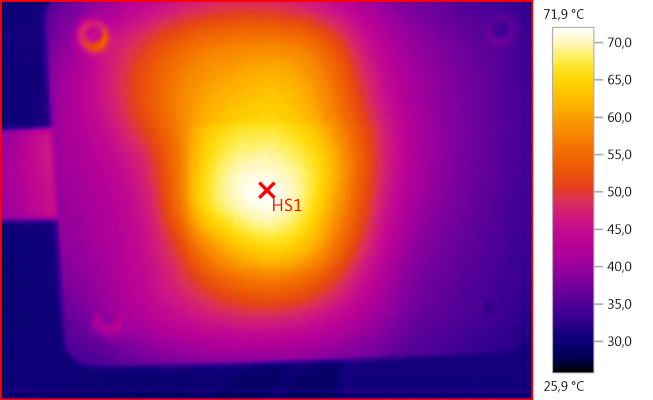
HS1: 71,9°C
HS1 is the transformer.
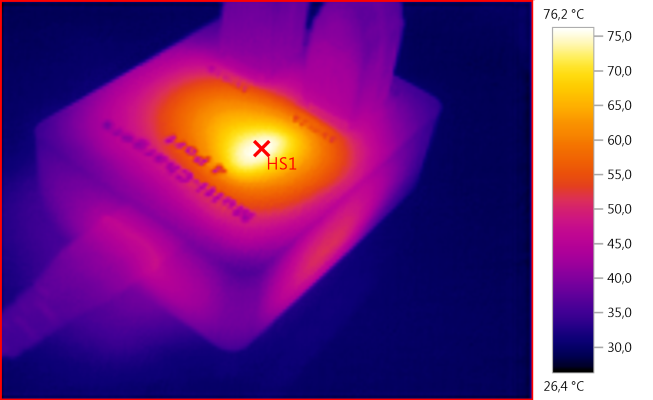
HS1: 76,2°C

There is a lot of noise at 0.5A: 84mV rms and 670mVpp.

It is about the same at 1A: 81mV rms and 600mVpp.
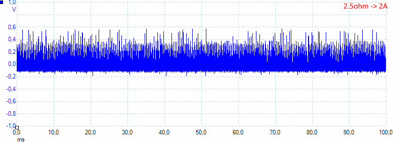
And gets worse at 2A: 155mV rms and 820mVpp.
Tear down
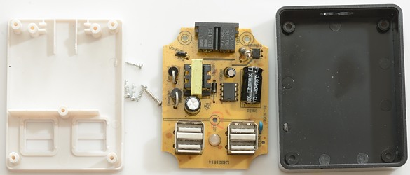
This was fairly easy to open, I had to remove four screws and then one to get the circuit board away from the lid.
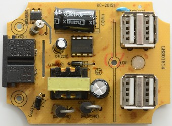
At the mains input there is a fuse and a bridge rectifier. The chip is a AP3970 12W switcher, this matches fairly well with 2A output.
Below the transformer there is two rectifier diodes in parallel. The blue safety capacitor is not a safety capacitor, but a 1kV standard capacitor (bad). Between the usb connectors is the blue led.
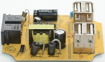
This side gives a better view to the two rectifier diodes.
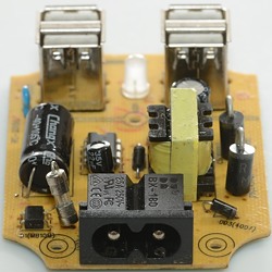
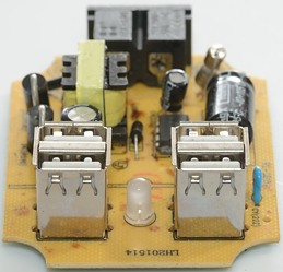
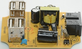
Here the "safety" capacitor can be seen.
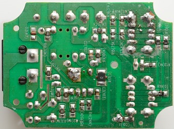
This side of the circuit board only has a few resistors. Notice all usb datapins are connected together, it is no accident they have the same coding.
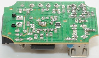
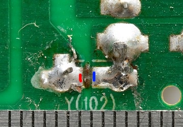
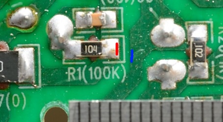
The first image is from under the "safety" capacitor, as usual there is supposed to be over 6mm, but there below 1mm. This will protect the capacitor from overvoltage, but not the user.
The charger passed the 2500 volt test, but failed the 5000 volt test
Conclusion
Very bad safety with the low creapage distance, not very much output power for a 4 port device, lots of noise and silly marking of the connectors.
I will not recommend using this charger.
Notes
Index of all tested USB power supplies/chargers
Read more about how I test USB power supplies/charger


