Disassembly of USB charged batteries
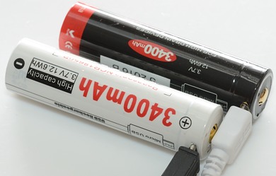
I have reviewed these two batteries and wanted to see how the electronic was made. I expected them to be about the same inside, except Lumitop must have two charge chips (There is a jump on the usb charge curve) and MecArmy must have one.
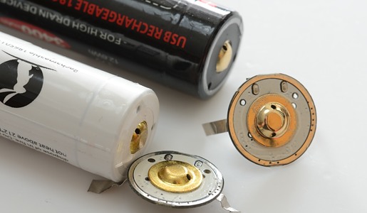
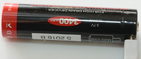
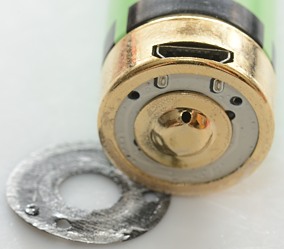
The usb charge circuit and protection is placed at the top of the battery.
Lumimtop
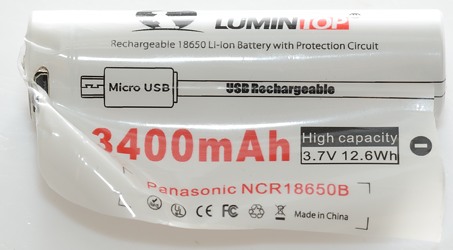
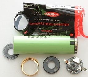
First step is to get rid of the wrapper.
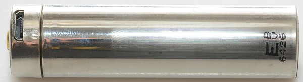
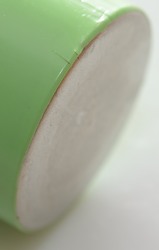
The cell inside is without any wrapper, this means the battery has slightly less diameter.
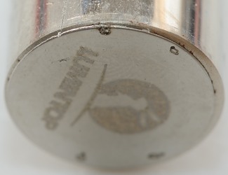
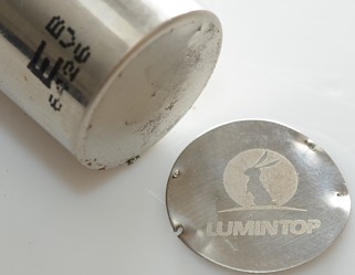
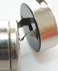
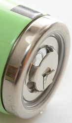
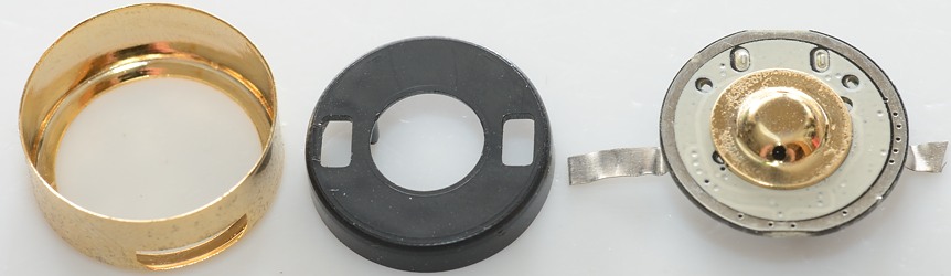
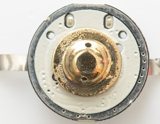
The backend of the battery has a extra metal plate, this makes the battery more robust for tail springs.
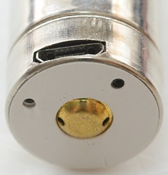
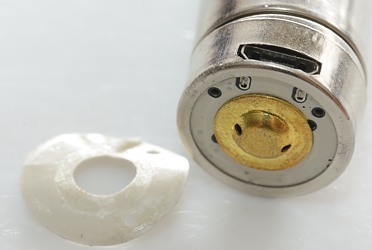
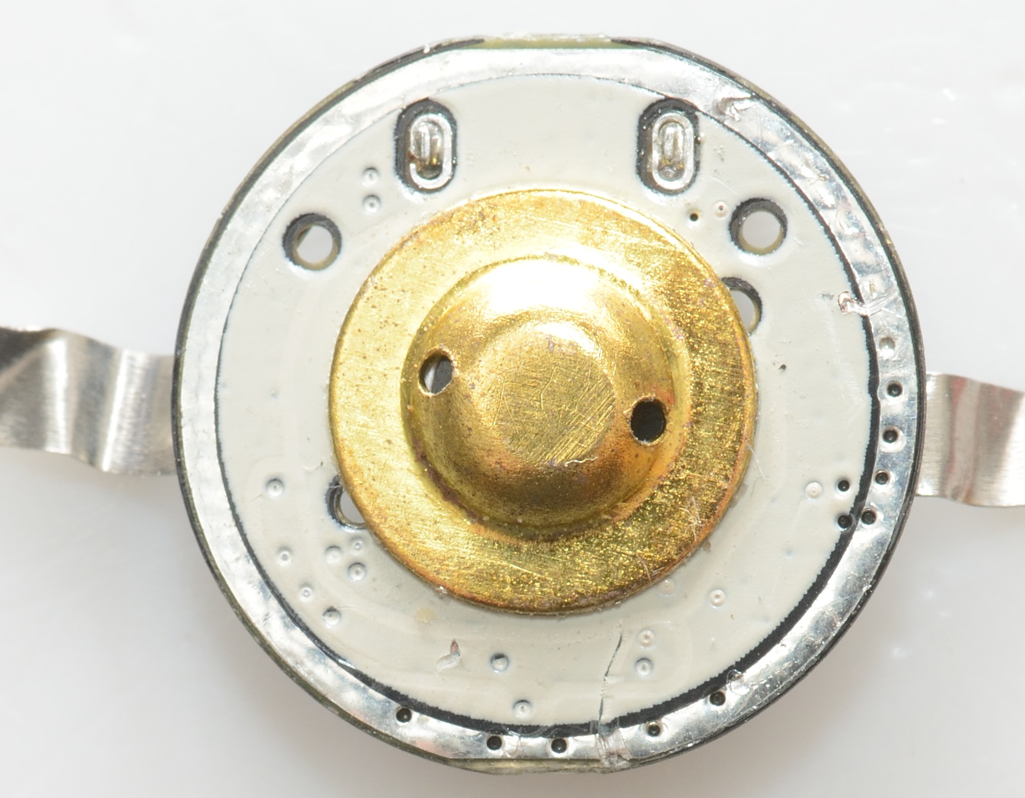
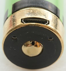
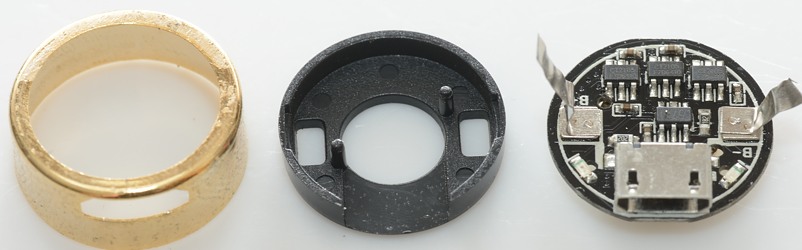
The front is an extra metal top with the electronic inside.
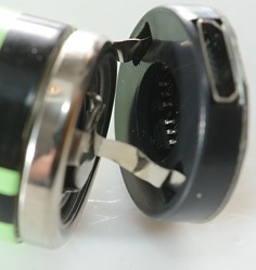
There is two connection with flat metal strips between the battery and the top (No surprise). The electronic can be pushed out of the metal top (More or less).
The shrink wrap helps with holding the top in place, when I had cut it the top was fairly easy to remove.
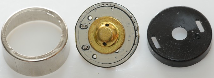
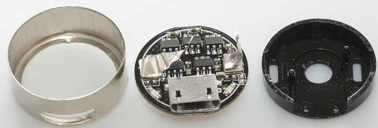
The top has the circuit board and a piece of plastic to keep the circuit board in place.
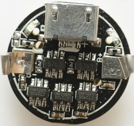
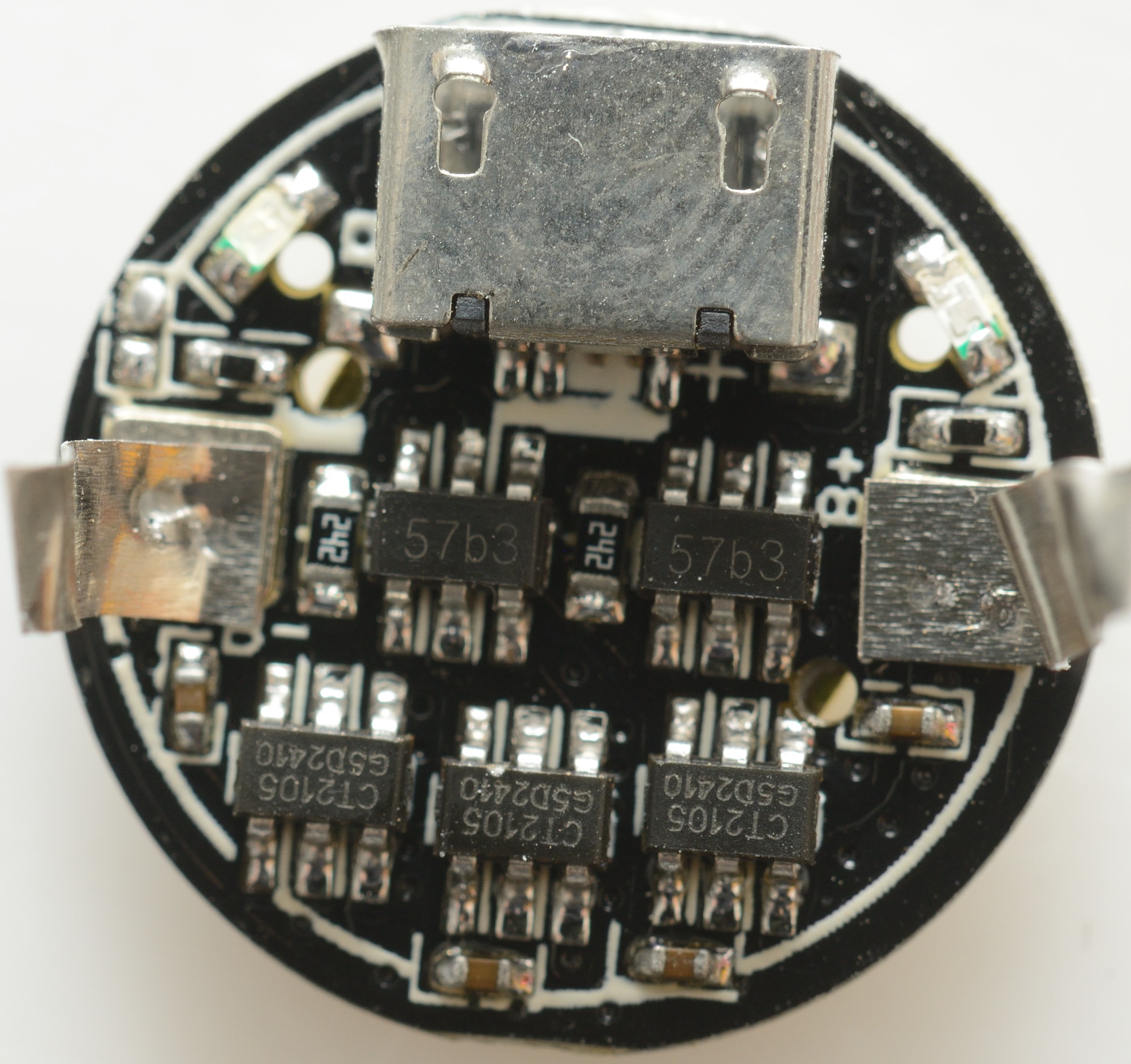
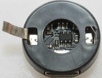
There is 5 chips on the circuit board. Two 57b3 (TP4057) charger chips and 3 CT2105 protection chips.
The charge chip has a 2400ohm resistor, this gives 0.41A charge current for each.
Each protection chip is rated for 3A at 25°C, it has an over temperature shutdown at 120° (Very nice).

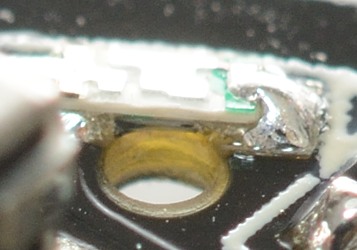
The led is not aimed out the hole, but up from the circuit board, i.e. the light seen in the hole is the reflection from the black plastic.
With the circuit free I did some measurement:
- Circuit battery discharge current at 4.2V is 5.7uA
- Circuit battery discharge current at 3.2V is 5.5uA
- Circuit battery discharge current at 2.8V is 5.5uA
- Circuit battery discharge current at 2.4V is below 0.01uA (Overdischarge protection tripped)
MecArmy
The MecArmy gets the same treadment.
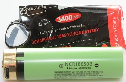
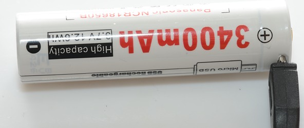
Here the original NCR18650B wrapper has not been removed, making the battery slightly thicker.
And there is no protection metal place at the bottom, making the battery slightly shorter.
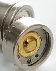
The top looks the same.
This time I could push the circuit board out.
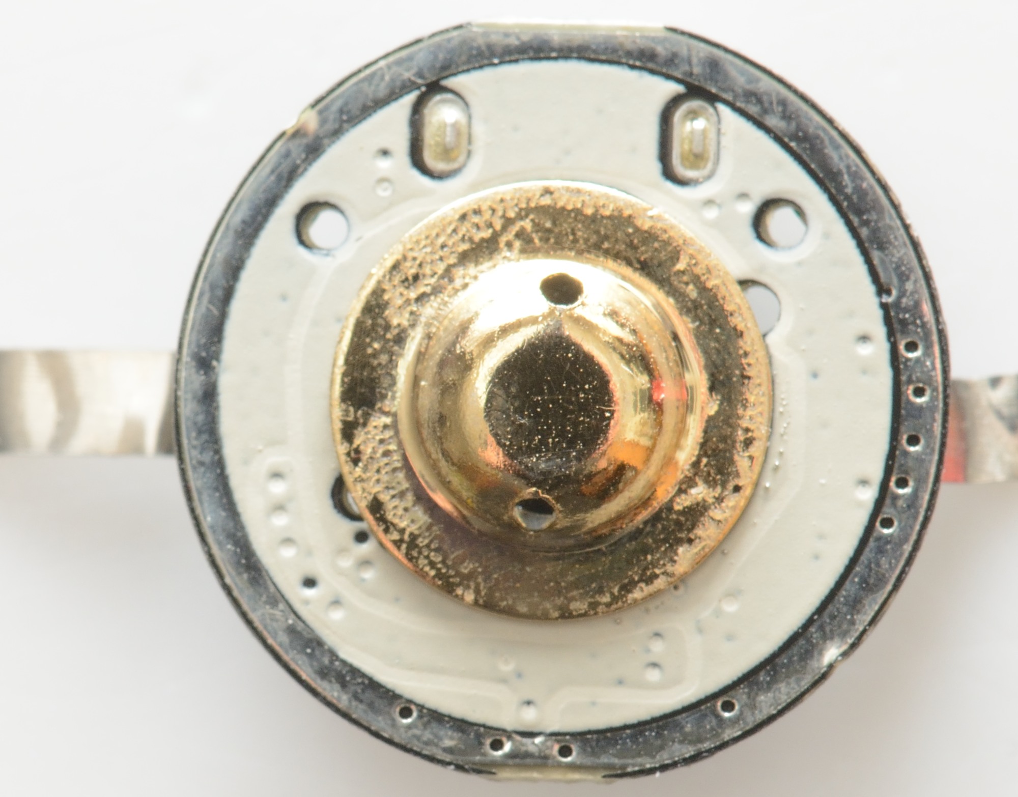
The top part of the original wrapper has been removed.
The outer ring is minus and the center is plus, any short between is very bad. When assembling these batteries they must be very careful with the plus metal strip.
The metal top and the plastic piece looks exactly the same as above.

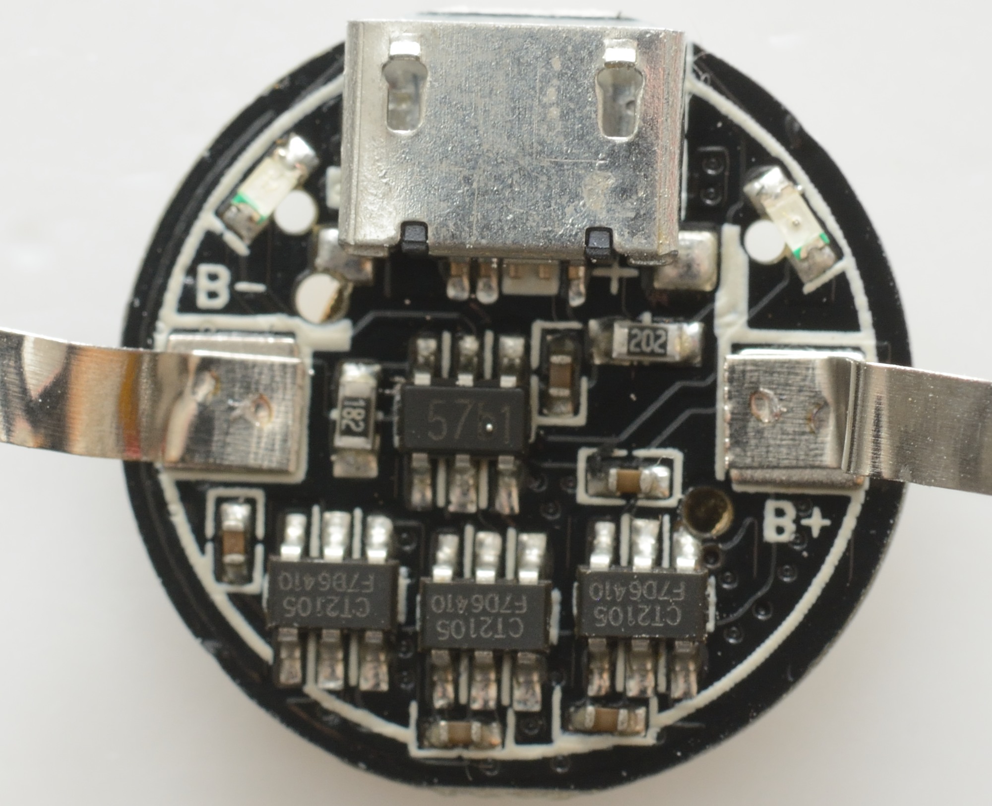
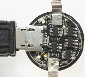
This circuit board only has one charge chip and 3 protection chips, both are same type as above.
The charger chip has a 1800ohms resistor, making the charge current 0.55A
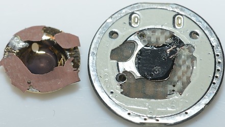
The top was rather difficult to remove, it looks like it was soldered to the circuit board.
With the circuit free I did some measurement:
- Circuit battery discharge current at 4.2V is 5.6uA
- Circuit battery discharge current at 3.2V is 5.3uA
- Circuit battery discharge current at 2.8V is 5.2uA
- Circuit battery discharge current at 2.4V is below 0.01uA (Overdischarge protection tripped)
Conclusion
The protection circuit is one chip, not a chip and one or more external dual mosfets, it makes the circuit slightly more compact. It would probably be better to use white plastic for the insert, instead of black, it would have made the leds brighter when looking into the two holes.
The Lumintop with the two charge chips charges faster and will also last better in light with a strong tail spring.
Both batteries looks well constructed and the low discharge current will not affect the lifetime.
Notes
Lumintop review MecArmy review
The calculated charge currents do not exactly match the measured values, this is due to tolerances in the chip and on the resistors.
A look inside some 18650 cells:
Disassembly of UltraFire 9900mAh 18650 battery
Disassembly of some UltraFire batteries
Disassembly of cheap 18650 battery
The protection with a protection chip and external mosfet transistor can be seen here:
The Anatomy of a bottom Protected LiIon Battery