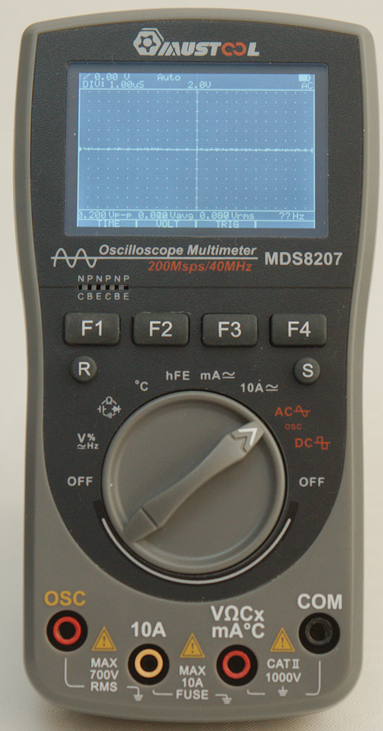
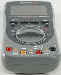
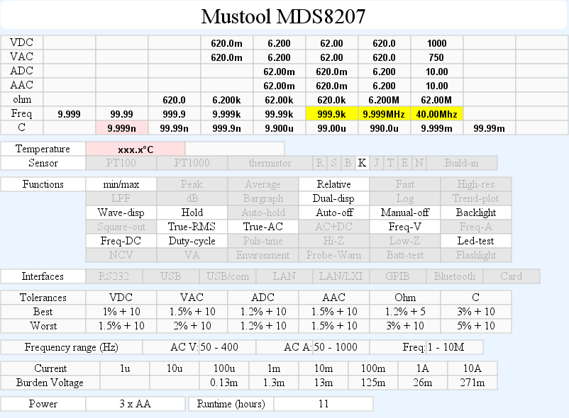
DMM Mustool MDS8207
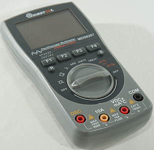
This is the latest incarnation (2019) of the Mustool DMM that can also show waveforms.
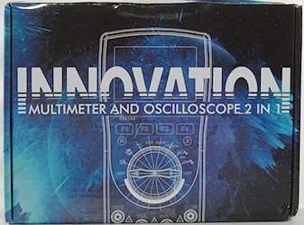
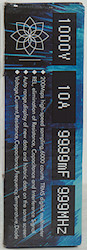
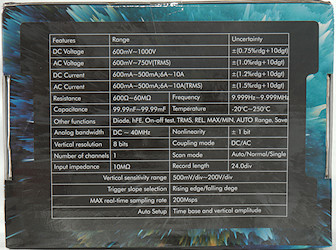
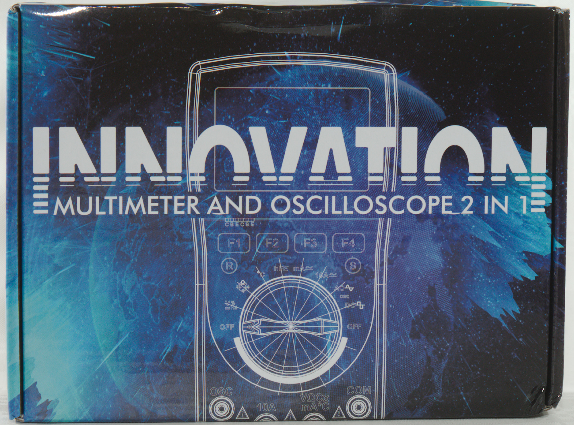
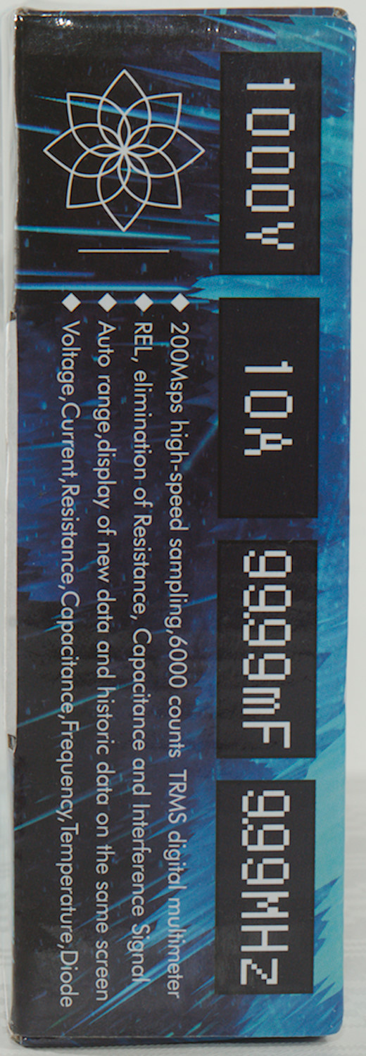
I got the meter in a cardboard box with specifications on it.
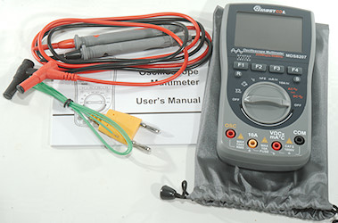
It included the DMM, a pair of probes, a thermocoupler, a bag and a manual.
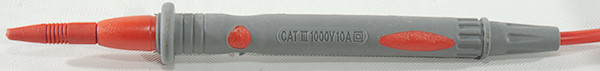
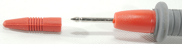
The probes include tip protectors, but they protect the full top and are not for CAT III rating.
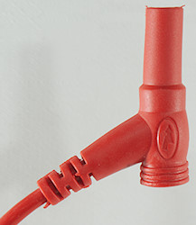
The plug is fully shrouded, but is slightly smaller than standard probe plug size.
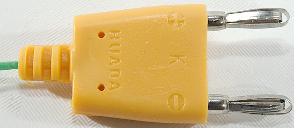

The thermocoupler is with a standard 19mm plug.
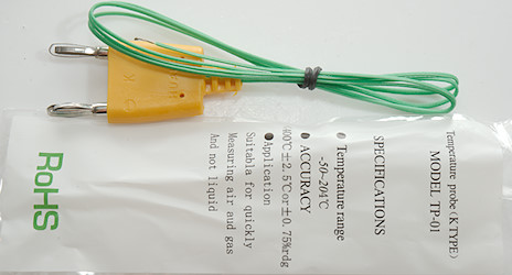
The bag with the thermocoupler did also include some specifications for it:
- Type: K
- Range: -50°C to 204°C
- Below 400°C it is +/2.5°C or 0/-0.75% How can accuracy be rated to 400°C when probe is rated for 204°C?
- Suitable for air or gas not liquid
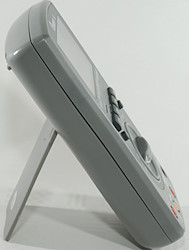
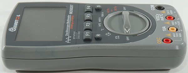
Both meter and tilting bale is smooth, this makes it difficult to use the meter one handed.
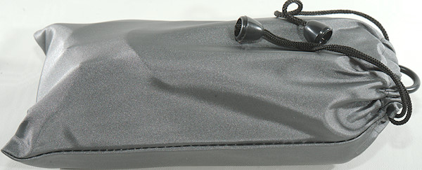
The bag can fit both meter and probes, but feels a bit tight when doing it (Meter fits easily in it).
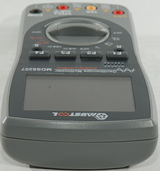
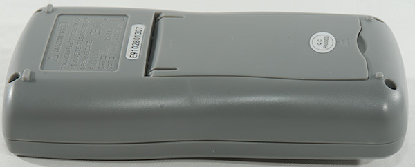
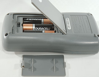
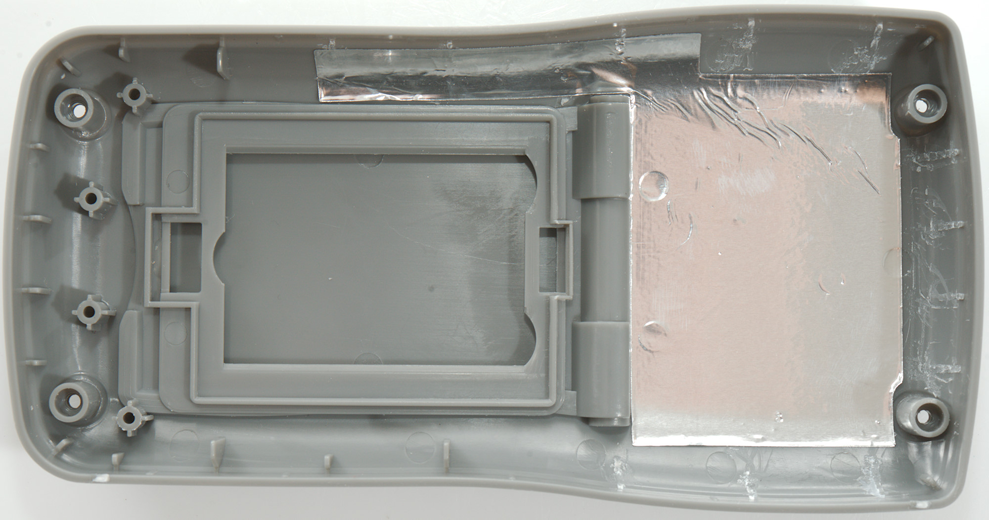
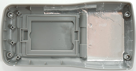
The battery lid do not use a screws.
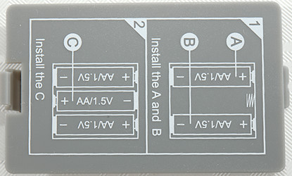
The graphic on the the battery lid specifies how to install the batteries.
Display
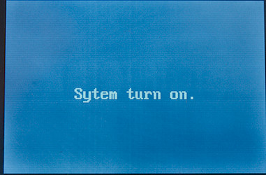
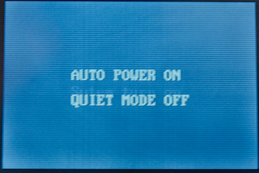
The power on screen shows the status for auto power on and sound, hold down F1 and/or F4 during power on to temporary change values.
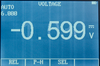
Typical display with range, unit and value. The bottom is the function of the soft keys (F1..F4)
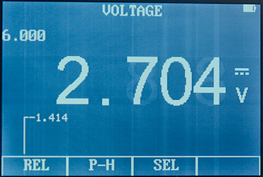
The REL is nice, it shows the reference value.
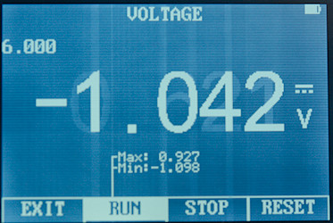
Min/max (P-H button) also shows the actual min/max below the actual value. Only issue can be reading the small numbers.
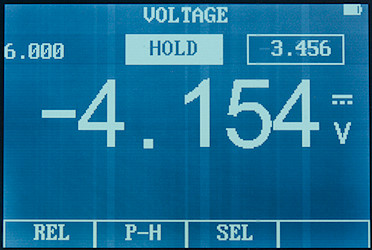
The hold button will freeze the big display, but the small value will continue to update.
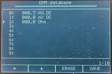
The database of saved values. This is activated by holding the S button down. To save the currently frozen value use arrow to select the desired slot, then press save (Default is always #0).
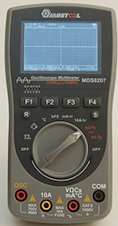
Functions
Buttons:
- F1..F4: Functions depends on actual mode.
- R: In DMM mode it is range select and in OSC mode it is auto setup.
- S: It is hold in both DMM and OSC mode. When reading is frozen hold it down to enter database.
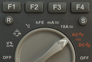
Rotary switch:
- Off: Meter is off.
- V: This is VDC/VAC/mVDC/mVAC/Hz/Duty-cycle, F3/SEL is used to select between DC/AC/Hz/Duty-cycle
 : ohm, diode, continuity and capacity, use F3/SEL to select.
- °C: Temperature with thermocoupler, use F1 & F2 to select between Celsius and Fahrenheit.
- mA: Milliampere range for AC and DC, use F3/SEL to select
- A: Ampere range for AC and DC, use F3/SEL to select
 : Oscilloscope mode with AC input
 : Oscilloscope mode with DC input
- Off: Meter is off.
Only difference between the two oscilloscope modes is a capacitor in series with the signal in AC mode.
Input
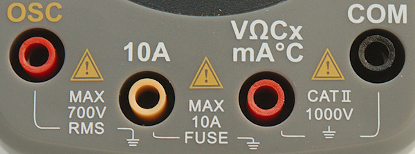
If you have multiple meters, be aware that this meter has placed the connection different than other meters.
- OSC: Oscilloscope mode
- 10A: High current (This can also be used a COM for OSC mode).
- xxx: All other ranges.
- COM: The common terminal for most ranges, large capacitor is excluded from this.
Waveform/Oscilloscope function
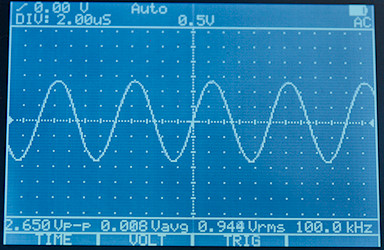
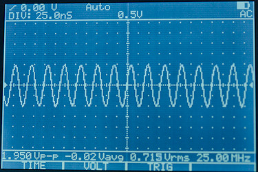
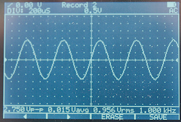
A 1Vrms sine wave curve at 100kHz and 25MHz (-3dB point).
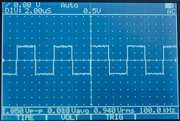
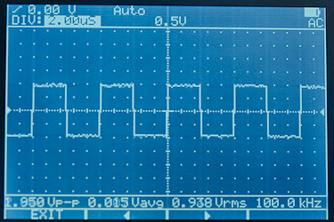
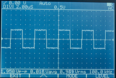
A 100kHz square wave.
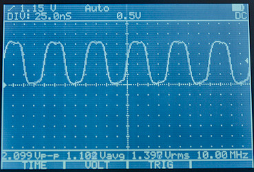
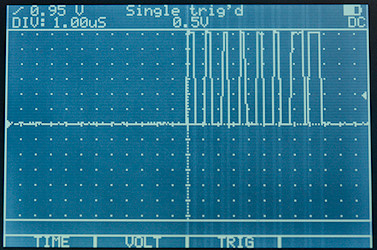
A 10MHz square wave in DC mode with trigger moved to a positive value (1.15V, see top of screen).
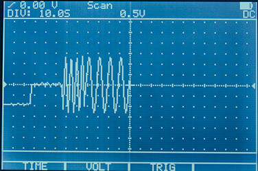
10s/DIV setting, AC mode cannot really be used here due to the slow signal. I do miss a restart button. At slow speed the single trig do not work.
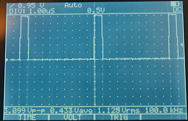
The DMM mode may not be good at fast PWM, but in OSC mode it is no problem to see a 3.3V 10% 100kHz PWM signal, but I must guess about the duty-cycle.
 z
z
Single pulse trigger can be used to capture communications, here it is the start of a NeoPixel message. I would have like to place the trigger at the screen edge to get more of the data, but that is not possible.
Pressing F1/TIME or F2/VOLT will enter range adjustment (it is units/DIV):
Time: 10s, 5s, 2s, 1s, 500ms, 200ms, 100ms, 50ms, 20ms, 10ms, 5ms, 2ms, 1ms, 500us, 200us, 100us, 50us, 20us, 10us, 5us, 2us, 1us, 500ns, 200ns, 100ns, 50ns, 25ns, 12.5ns
Volt: 0.5V, 1V, 2V, 5V, 10V, 20V, 50V, 100V, 200V
The lowest voltage settings is not very sensitive.
The trigger menu where it is possible to set raising/falling trig, single, normal, auto mode and move the level.
The manual also says something about cursors, I did not see them while use the oscilloscope mode.
It is possible to save waveforms. First press the S/HOLD button to freeze the waveform, the hold down the S/HOLD button to enter the database, finally press F4/SAVE to save the waveform. These saved waveforms are remembered when power is off and there is space for 50 of them.
Measurements
- Volt and frequency (DMM mode)
- At 1Vrms frequency input range is from 10Hz to 30kHz
- At 7Vrms frequency input range is from 0.8Hz to 150kHz
- Frequency counter requires a zero crossing.
- Duty cycle works from 20% to 80% at 10kHz with 4Vpp, precision is within 13
- Duty cycle works from 5% to 95% at 1kHz with 4Vpp, precision is within 1
- 1 VAC is 5% down at 2.1kHz
- Min/max needs about 0.5s to capture a value, but it may requires many pulses (0.7s is much better).
- Input impedance is 10-11Mohm on DC, AC.
- Maximum voltage is 1000VDC and 750VAC
- Oscilloscope mode
- Input impedance is around 10Mohm
- AC mode has a capacitor in series with the input.
- -3dB is around 25mHz
- Current
- mA protected by 0.5A/250V probably a PTC
- A is protected a 10A/250V SMD fuse
- Ohm, Continuity, diode and capacitance
- Ohm needs about 3s to measure 100ohm
- Ohm is 1.0 open and -0.5mA shorted
- Continuity is 1.0V open and 0.5mA shorted
- Continuity is very fast (Less than 5ms).
- Continuity beeps when resistance is below 50ohm.
- Diode range uses 3.2V, max. display is 3.000V at 0.18mA, max. current is 2.2mA shorted
- 10uF takes about 4 seconds to measure.
- 70000uF takes about 8 seconds to measure.
- Ohm and capacity input is rated for 250VDC/AC overload.
- Miscellaneous
- Current consumption of meter is 145mA (OSC at 5V/DIV or above is 175mA).
- Meter works down to 3.5V where it will turn off, battery symbol shows empty at 3.5V
- Display backlight fades slightly with falling battery voltage.
- Meter reading is stable with falling battery voltage.
- The meter often needs a couple of updates to show correct value.
- Viewing angle is good
- Display updates slightly below 2 times/sec
- Will automatic turn power off in about 14 minutes.
- Standard probes cannot be fully seated
- Weight is 281g without accessories, but with batteries.
- Size is 160 x 82.5 x 37mm.
- Probes
- Probe resistance 95mOhm for one.
- Probe wire is soft and 82cm long.
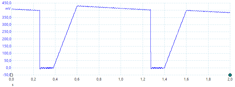
A look at the capacitance measurement waveform for a 1uF capacitor.
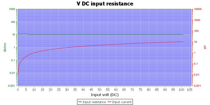
Input impedance in volt and frequency mode
AT 10A the reading will slowly increase and after some time (about 30s) be out of specified tolerance. Specifications says range must not be used more than 30s at a time.
The lowest capacity range shows about 5% high at 1nF, but zero is correct.
Temperature has a 10°C offset.
Frequency only works up to 150kHz on V input, higher frequencies can be measure in oscilloscope mode.
NiMH will give slightly longer runtime, lithium will double runtime.
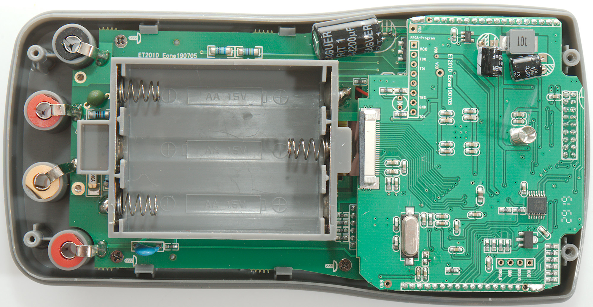
Tear down
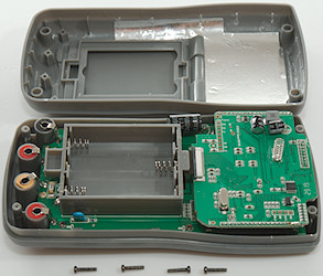
To open the meter I had to remove four screws.
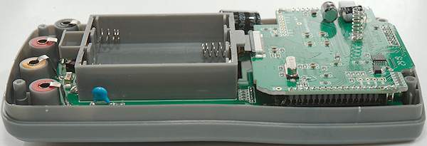
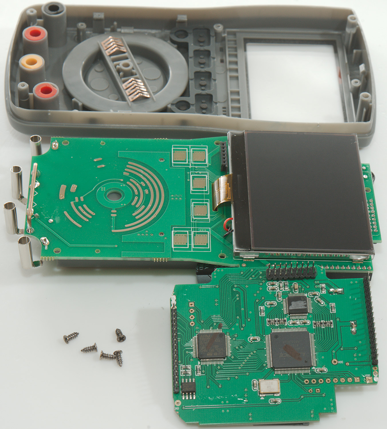
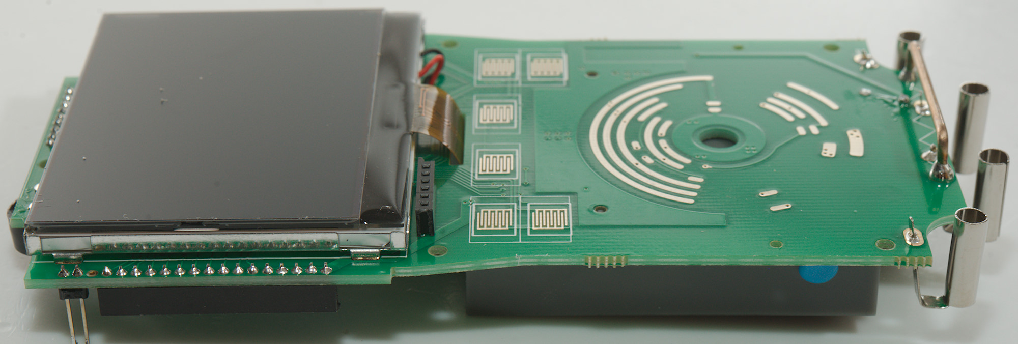
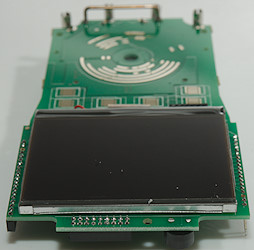
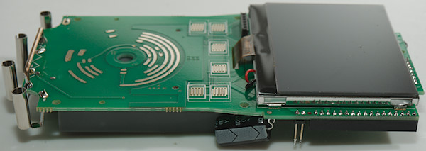
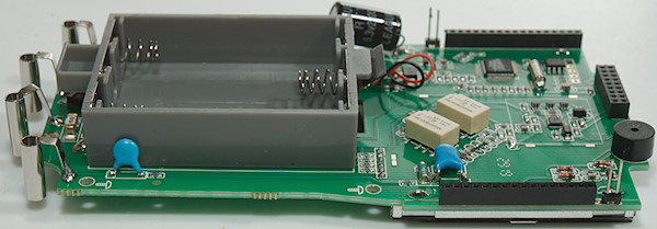
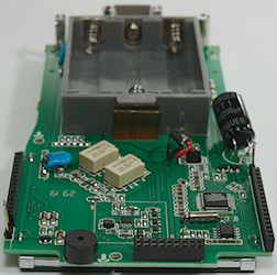
The meter uses two circuit board and they are soldered together with a screw below the top board.
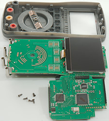
I had to unsoldering the boards from each other and removing the 5 screws that holds the bottom board in to get them out.

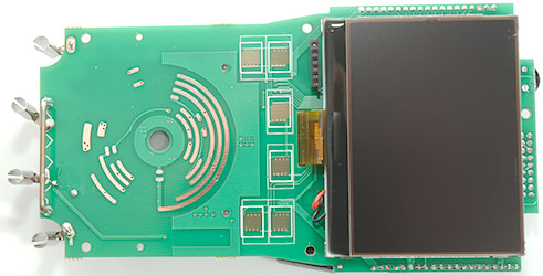
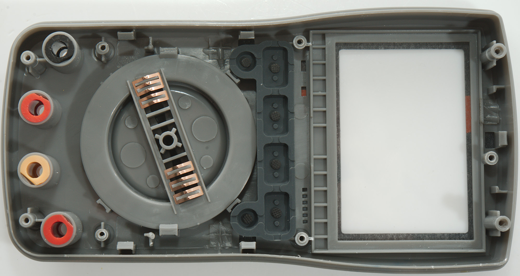
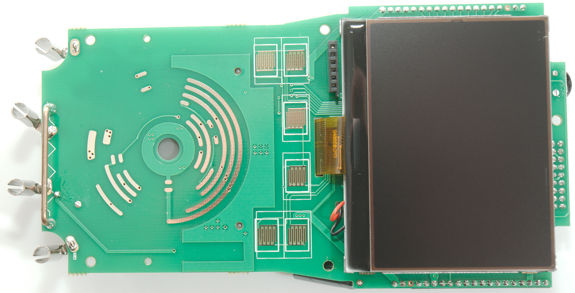
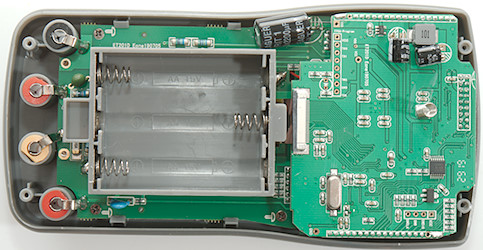
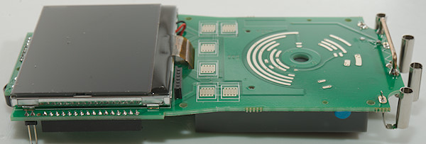
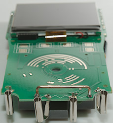
The display (backlight) is also soldered to the circuit board and there is nothing below it. This means this side of the circuit board is pads for the buttons and the rotary switch, inputs for the transistor tester and the current shunt.
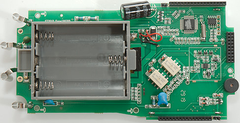
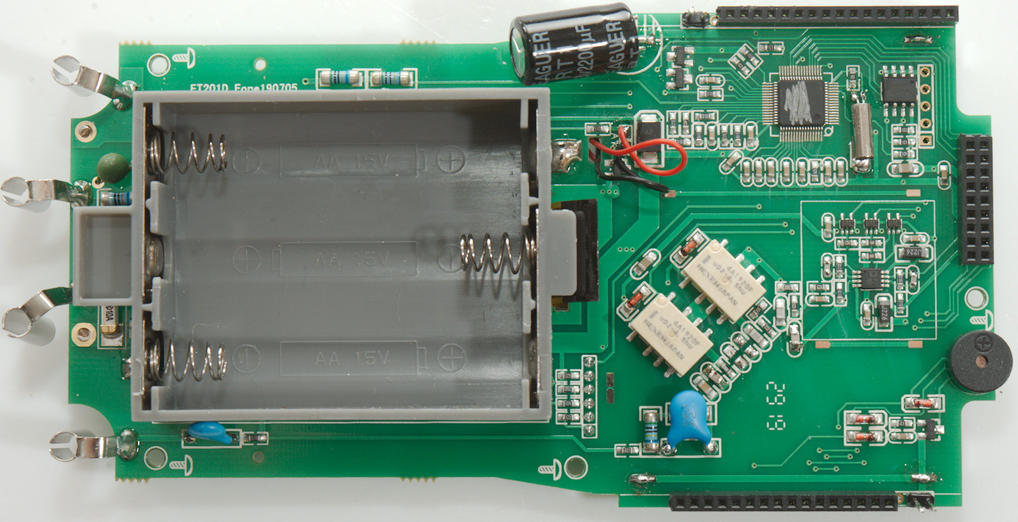
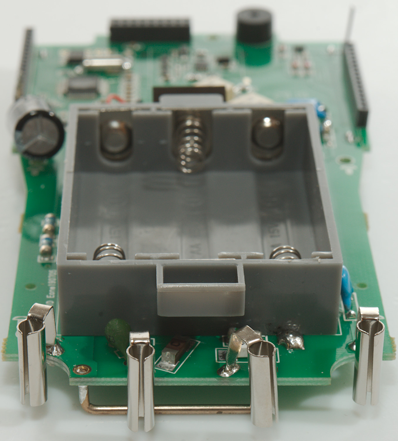
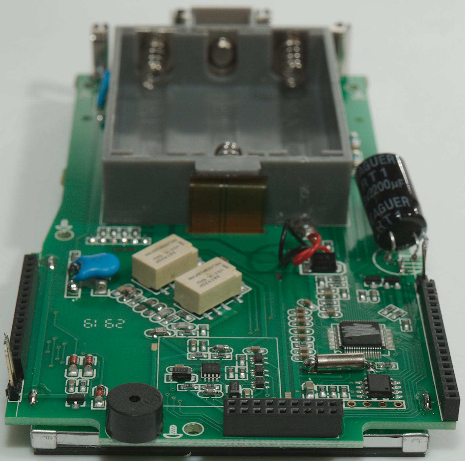
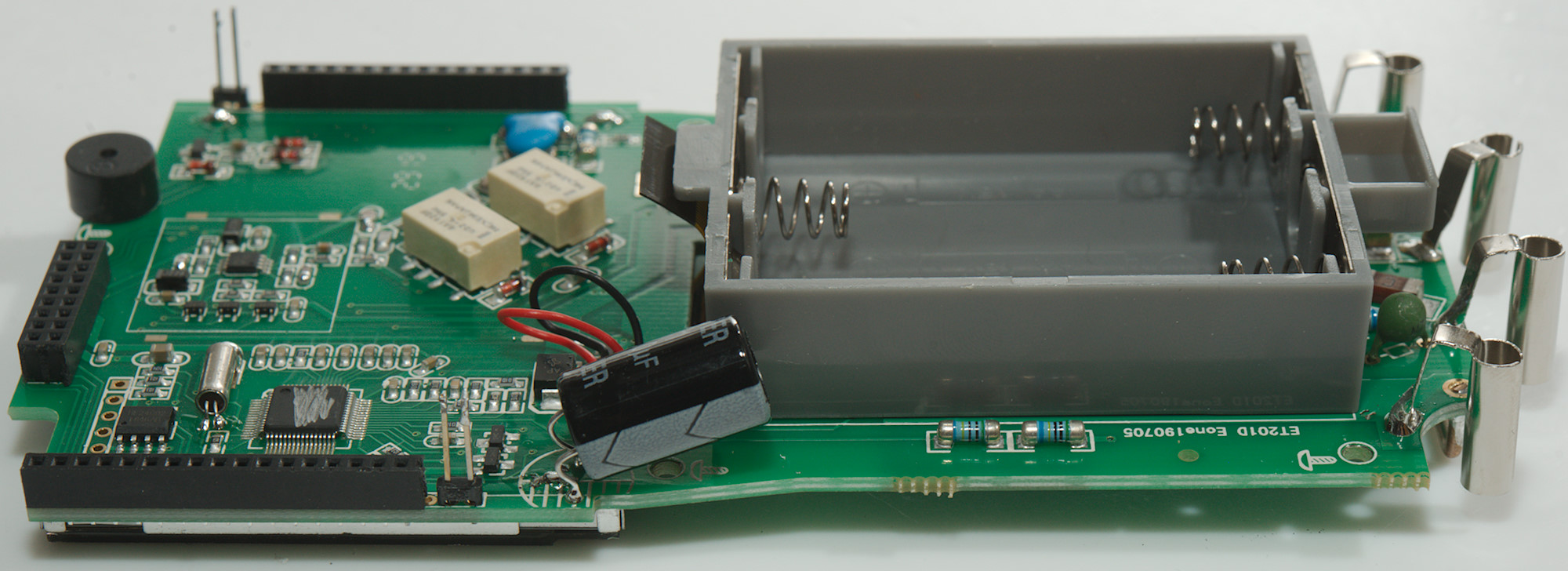
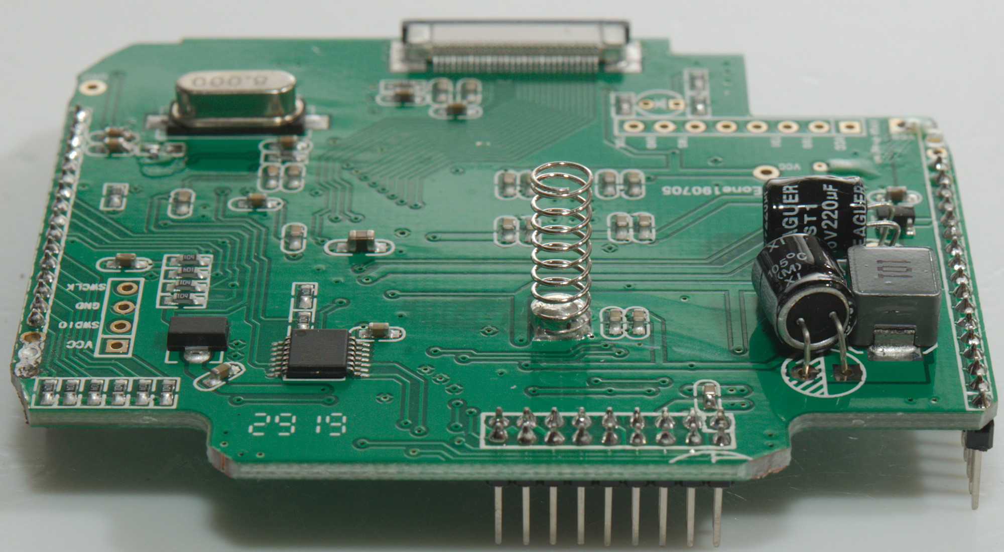
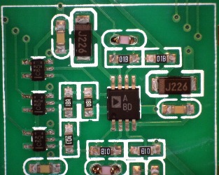
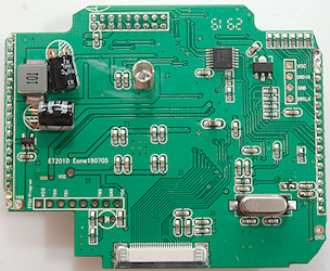
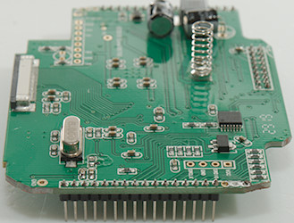
On this side is the input circuit. The 10A current uses a SMD 10A fuse and probably a PTC for the mA input, there is also the usual PTC and resistor (900kOhm) for ohm input . The volt input uses two resistors (2x5Mohm) directly connected to the multimeter chip. The typenumber is removed from the multimeter chip, but it has a EEPROM (24C02) connected.
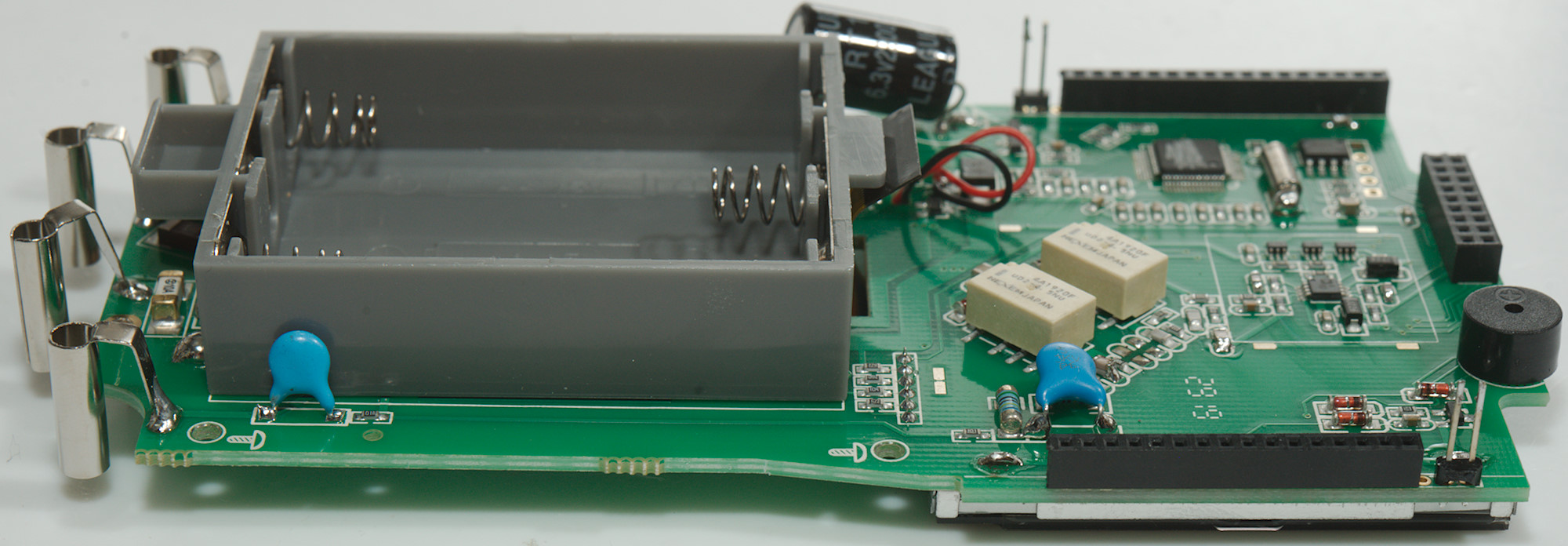
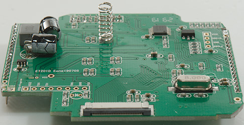
The OSC input has a optional capacitor (4.7nF 2kV) beside the battery box. Next is two input resistors (2x5Mohm) and a blue capacitor across the resistors. There is two relays and probably some analog switches to handle range selection
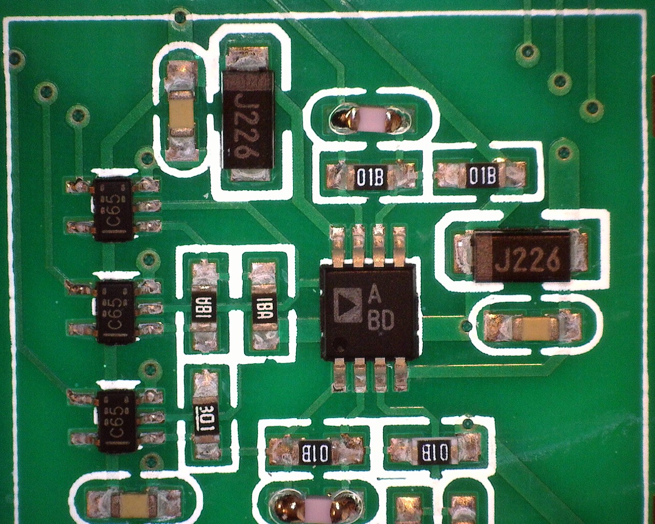
ADC circuit. The C65 may be a SN74LVC1G66 analog switch.


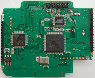
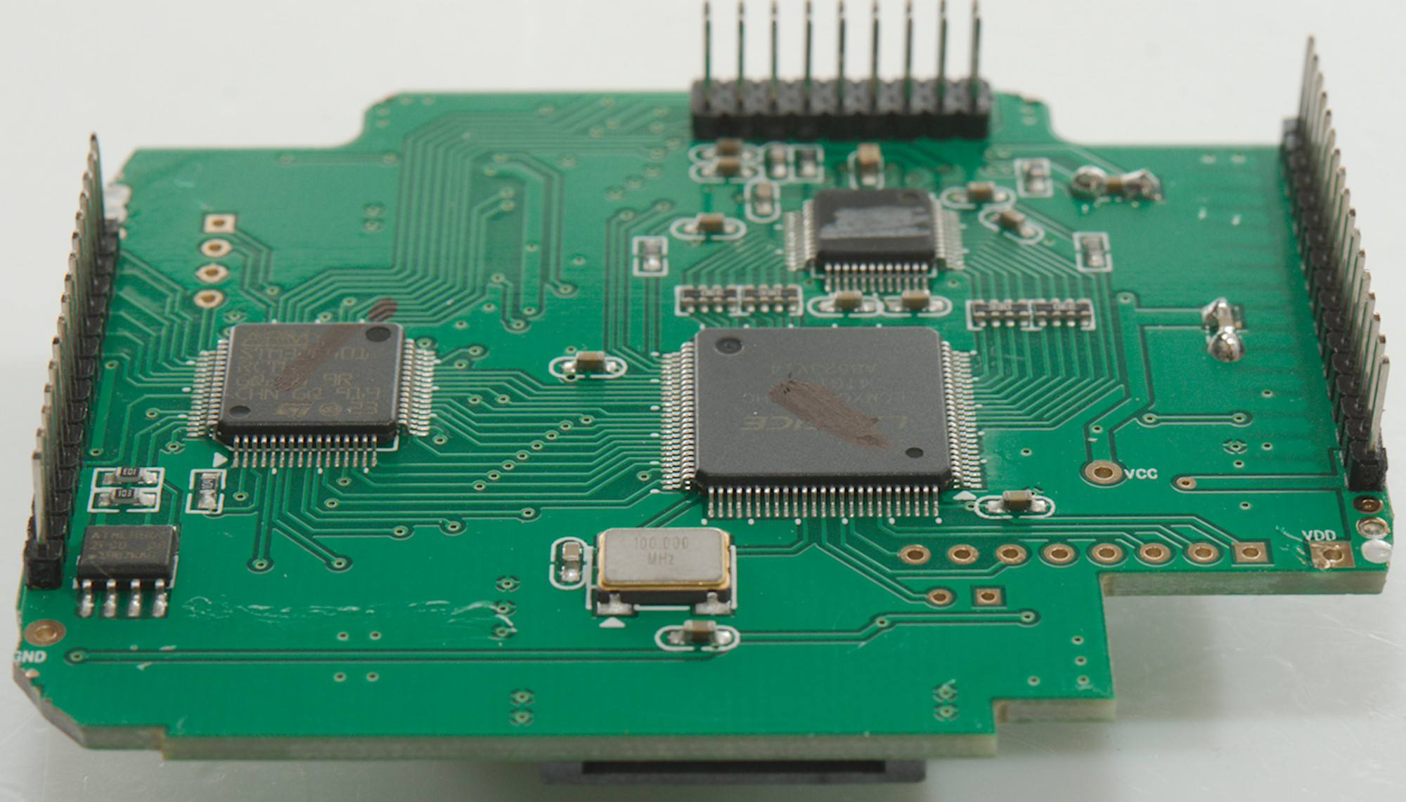
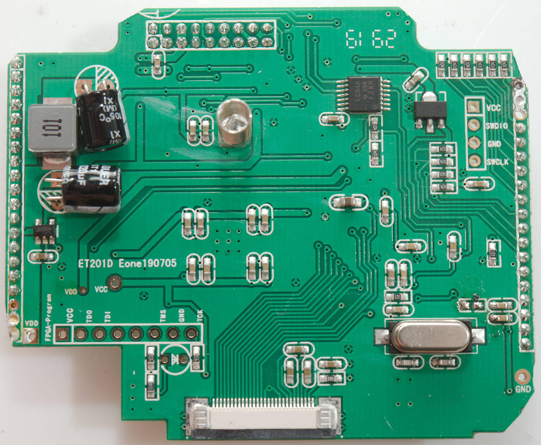
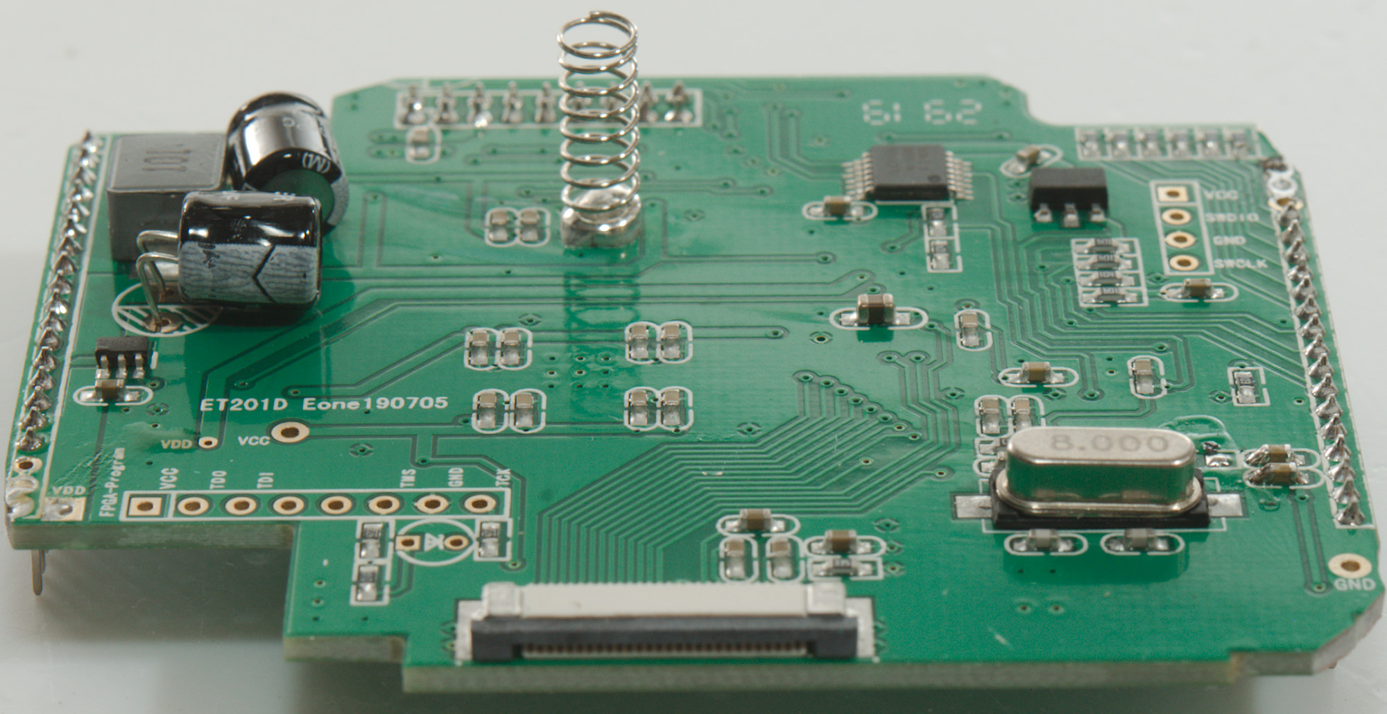
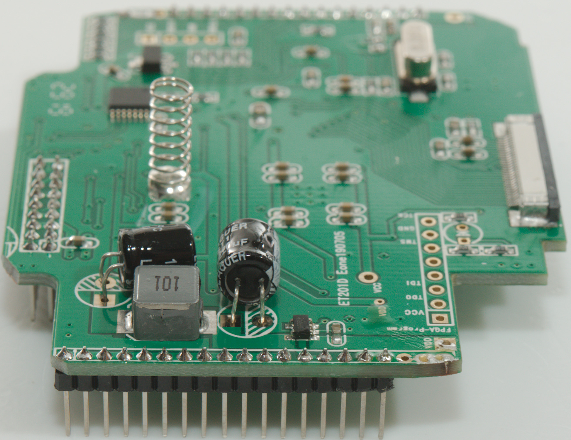
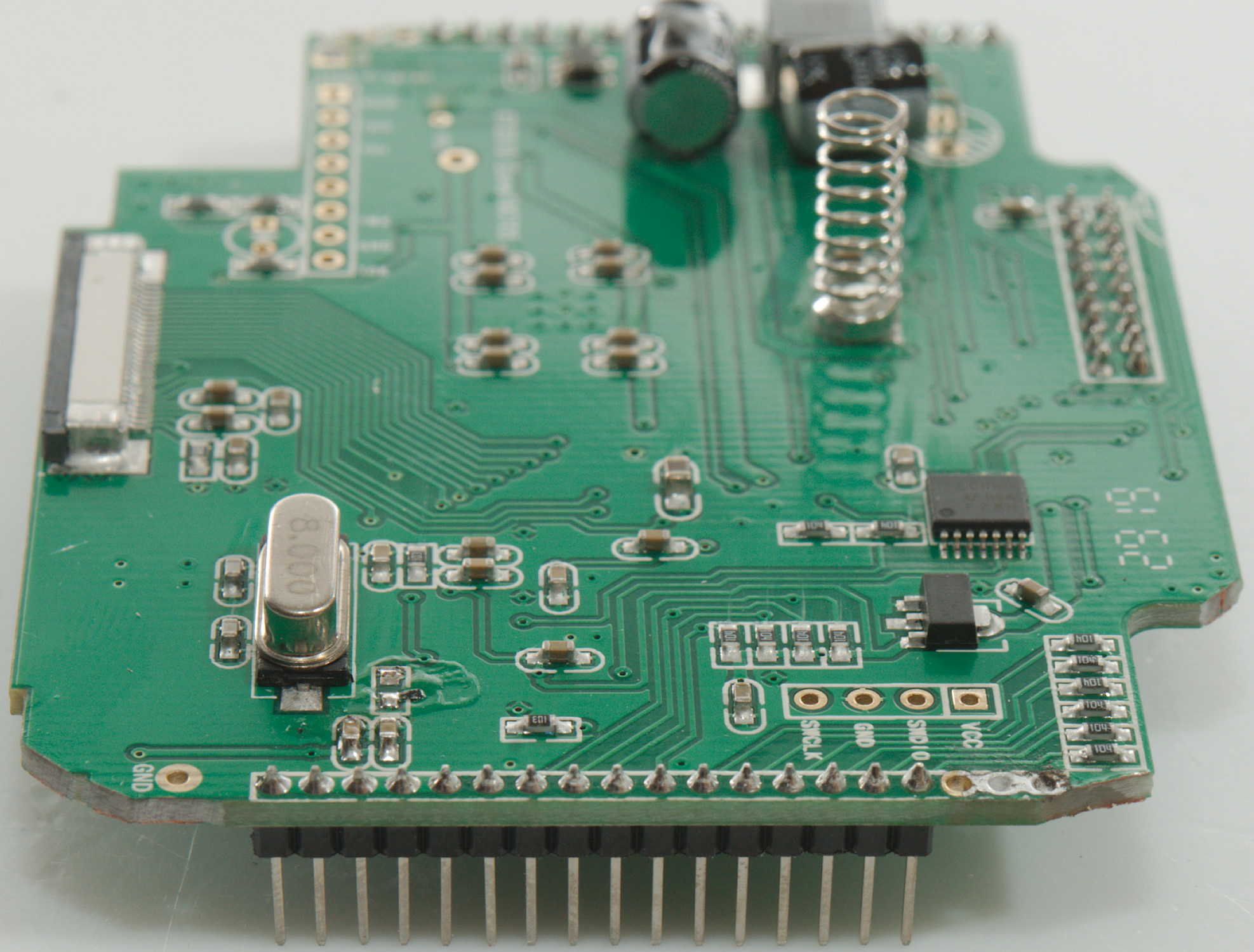
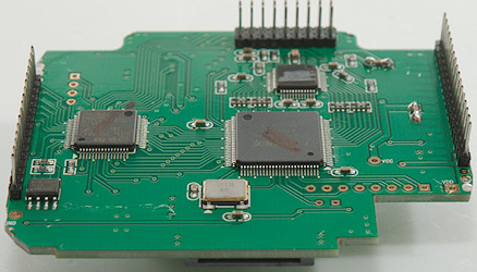
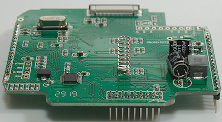
The other circuit board has all the digital logic controlled by a microprocessor (STM32F401RCT), a FPGA (LCMX02-640HC) to do all the fast stuff and a chip with markings removed. There is also a 8 pin chip (ATNLH9072), maybe a EEPROM.
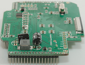
On this side is a voltage regulator (7133-1) and some logic inverters (LC04A). The inductor (Marked 101->100uH) is some power filtering.
Conclusion
As usual I doubt the CAT, a small SMD fuse cannot handle high voltage and current and the transistor tester makes it way to easy to touch high voltages.
This meter is much better than the two previous models, the multimeter is very similar to many other multimeters, but the graphic displays is used to improve some functions. The oscilloscope mode works this time, it has a good bandwidth, AC/DC works as expected, but there are still a lot of rough edges.
The battery life is bad for a multimeter, it is best to use recharge batteries.
Notes
The multimeter was supplied by banggood.com for review (I believe that Mustool is a Banggood brand).
How do I review a DMM
More DMM reviews