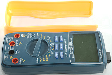
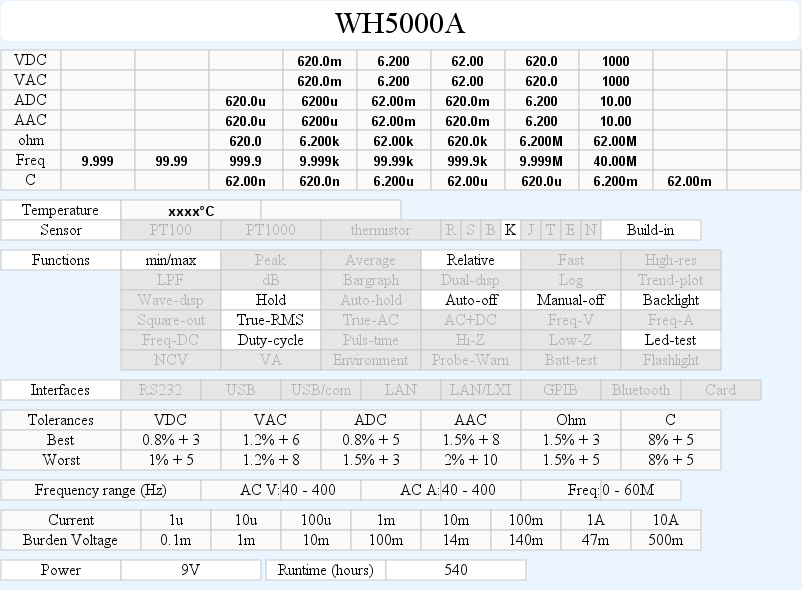
DMM WH5000A
This meter do not have a brand, but has lot of ranges and functions.
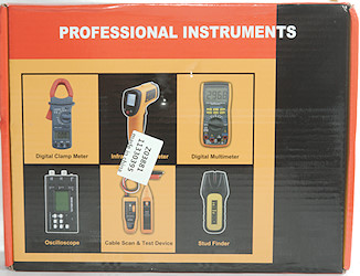
The meter arrived in a cardboard box without any information on.
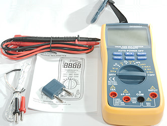
The box contained the meter, probes, thermocoupler, magnet, strap, transistor tester adapter and a manual.
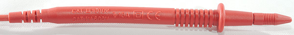

Probes are not branded and are specified for CAT III and CAT IV, this cannot be true with that much tip exposed.
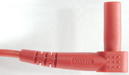
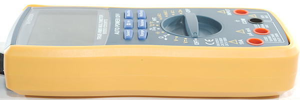
The plug is fully shrouded but a bit short.
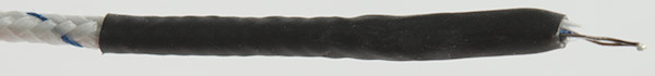
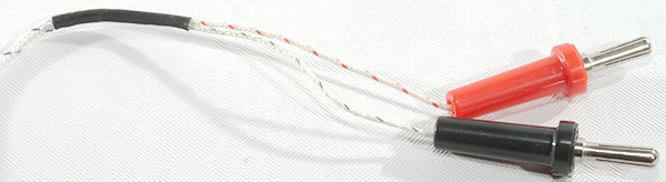
A standard cheap thermocoupler with a two banana plugs.
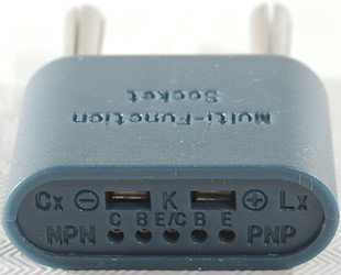
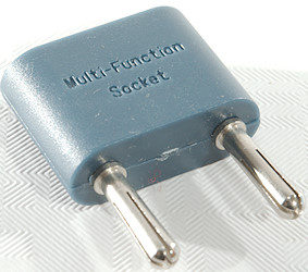
The transistor tester, thermocoupler, capacitance tester socket.
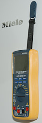
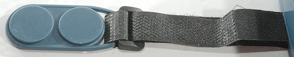
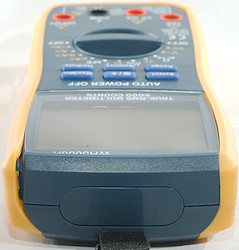
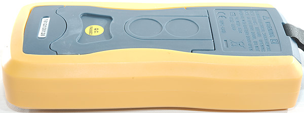
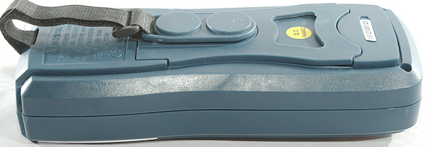
The meter includes a strap with a magnet.
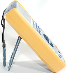

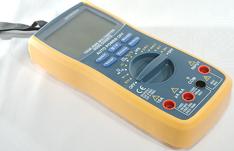
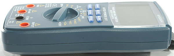
The rotary switch and button can be used single handed when using the tilting bale.
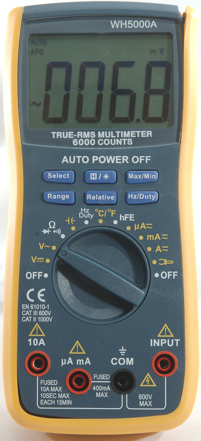
Display
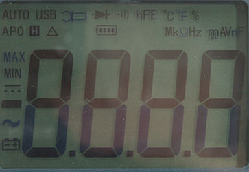
The above picture shows all the segments on the display, a few of them are not used.
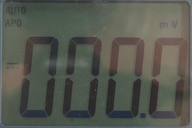
Usually the meter shows the selected range and the value.
Functions
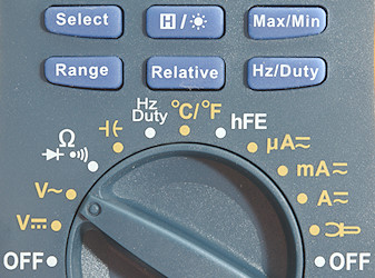
Buttons (Range selection and a few other are remembered):
- Select: Select AC/DC in current, ohm/continuity/diode and Celsius/Fahrenheit
- H: Freeze the display, press again to release. Hold down to turn backlight on.
- Max/min: Capture maximum and minimum values, the sequence is max/min/normal, during normal max/min is cleared.
- Range: Switch to manual range and select range, hold down to activate automatic ranging again.
- Relative: Remember current value and show further values relative to this, press again to disable.
- Hz/Duty: Select frequency in AAC modes, will also change between frequency and duty cycle in Hz mode.
REL and max/min will disable auto ranging.
Rotary switch:
- Off: Meter is turned off.
- VDC: Voltage DC including mVDC
- VAC: Voltage AC including mVAC
 : Resistance, continuity and diode
 : Capacitance
- Hz Duty: Frequency and duty cycle.
- °C/°F: Measure temperature with a thermocoupler, will display meter temperature when no thermocoupler is connected.
- hFE: Transistor tested, requires supplied adapter.
- uA: The uA range.
- mA: The mA range.
- A: The A range.
 : Current clamp input, 1mVAC is shows as 1AAC
- Off: Meter is turned off.
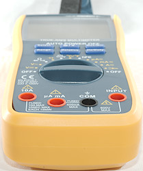
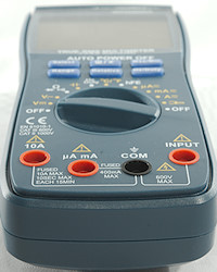
Input
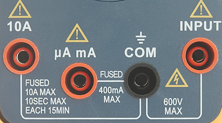
- A: High current, maximum current is 10A
- uAmA: Low current, maximum current is 600mA
- CON: The common terminal for all ranges.
- xxx: All other ranges.
Measurements
- Volt and frequency
- At 0.1Vrms logical frequency input (Hz) range is from 1Hz to 4MHz
- At 1Vrms logical frequency input (Hz) range is from 1Hz to 40MHz
- Logical frequency input (Hz) requires a zero crossing.
- Duty cycle works from 2% to 99% at 100kHz with 1Vpp, precision is within 0.4
- 1 VAC is 5% down at 2.0kHz (RMS will not work at the frequency).
- Max/min needs about 370ms to capture a voltage
- Input impedance is 10-11Mohm on mVDC/mVAC/DC/AC
- Frequency input has above 1Mohm up to about 2V then drops to about 2kOhm
- Rated overload protection on VDC ranges is 600VDC or VAC, but it is rated for 1000V DC
- Rated overload protection on VAC ranges is 600VAC, but it is rated for 750V AC
- Current
- Overload protection in uA and mA: 0.4A/600V 6x30mm fuse
- Overload protection in A: 10A/600V 6x30mm fuse
- The mA fuse cannot handle the full 0.6A for long, because it is only 0.4A
- Clamp input is AC and 1mV/A and a maximum of 620mV/620A
- Ohm, continuity, diode and capacitance
- Ohm needs about 3s to measure 100ohm
- Ohm is 1.0V open and 0.34mA shorted
- Continuity is fast (15ms).
- Continuity beeps when resistance is below 50ohm
- Continuity is 1.0V open and 0.34mA shorted
- Diode range uses 3.3V, max. display is 3.000V at 0.14mA, max. current is 1.5mA shorted
- 10uF takes about 4.5 seconds to measure.
- 11000uF takes about 9 seconds to measure.
- Rated overload protection on ohm ranges is 250 VDC or VAC
- No rated overload on capacity ranges, but a reference to the uAmA fuse as protection.
- Miscellaneous
- Current consumption of meter is 1.0mA-2.0mA (9mA with backlight on)
- Meter works down to 2.2V, where it turns off, battery symbol show at 6.7V.
- The meter reading is stable until the meter turns off.
- Backlight is stable down to 4V then it start to fade and is just about off at 2.6V
- The meter may need a few display updates before it shows the correct value.
- Viewing angle is good
- Display updates around 4 times/sec
- Backlight is blue and will turn automatic off after 15 seconds.
- Will automatic turn power off in about 15 minutes
- Standard probes cannot be pushed fully down.
- Weight is 355g with magnetic hanger and batteries
- Size is 190 x 86 x 46mm, thickness includes magnetic hanger.
- Probes
- Probe resistance about 25mOhm for one.
- Probe wire 90cm long.
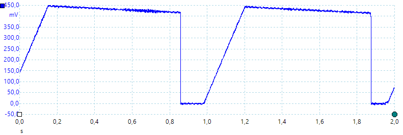
A look at the capacitance measurement waveform when measuring 1uF
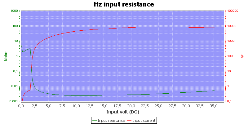
Frequency input resistance, the impedance is a bit above 1Mohm up to around 2V where it drops to 2kOhm
Large DC values may prevent the meter from showing AC values and may even reset it.
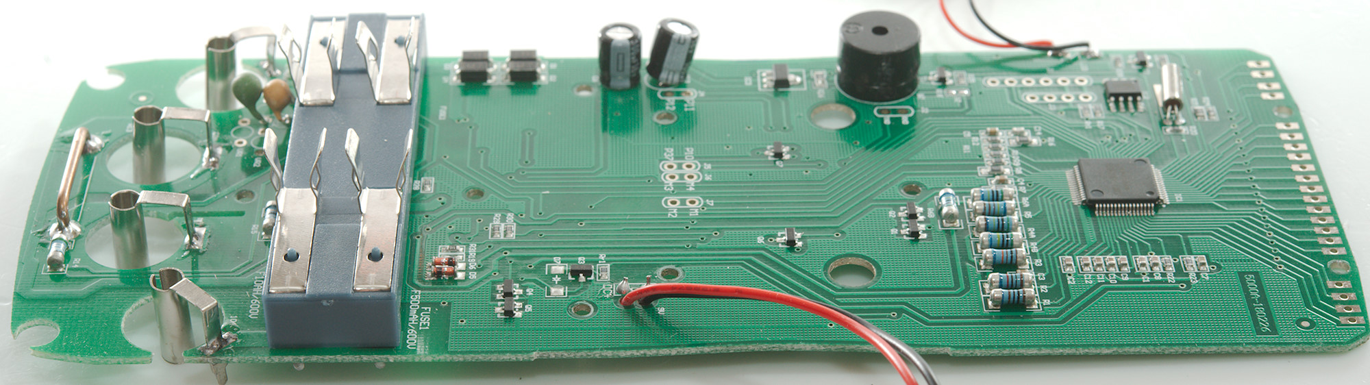
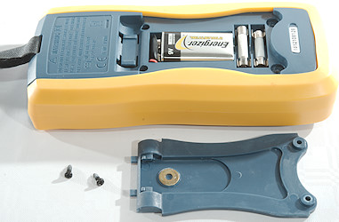
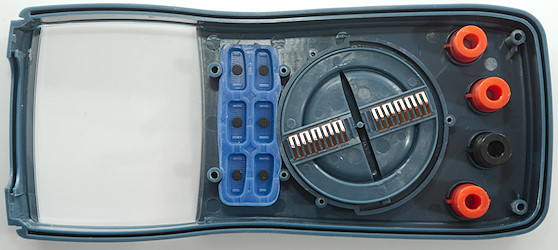
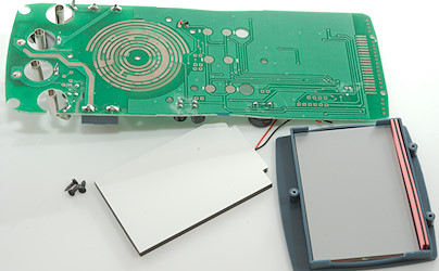
Tear down
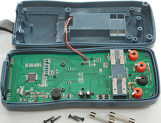
I had to remove four screws and two fuses to open the meter. I do miss some external markings which fuse goes into which holder, it is marked on the circuit board.
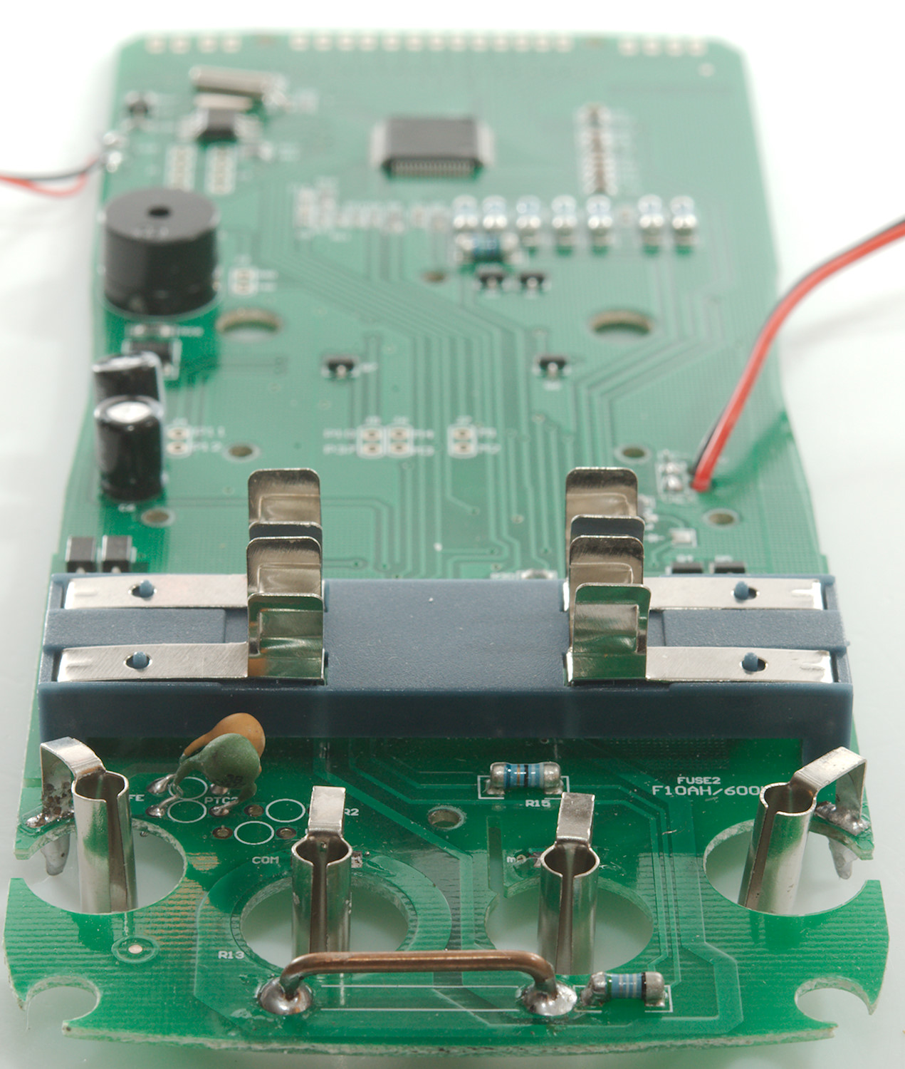
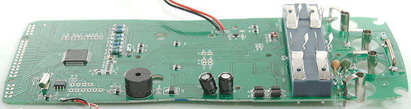
The fuses are mounted on a bridge across the circuit board, nice solution to make them external accessible.
Five more screws and I could remove the circuit board. In fact I only needed to remove two screws!
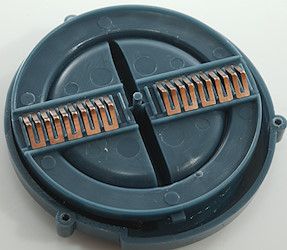
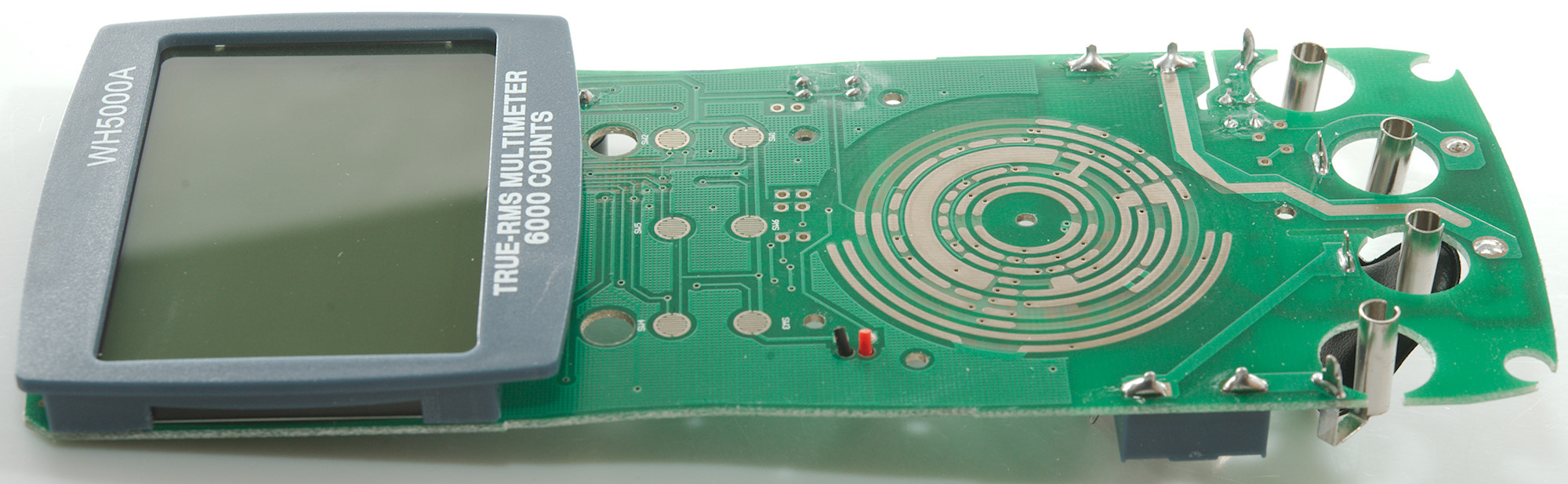
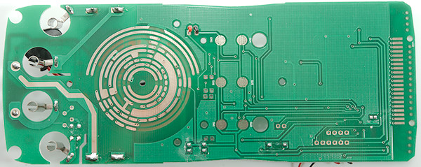
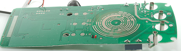
The range switch is mounted on the circuit board with 3 screws and it is not necessary to remove it.
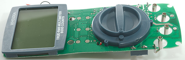
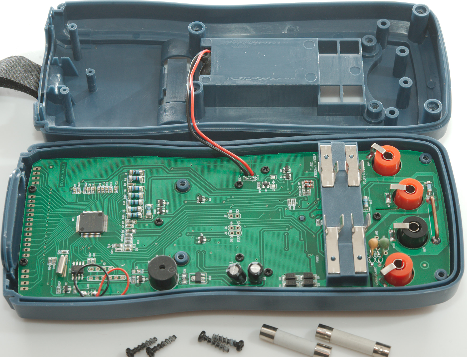
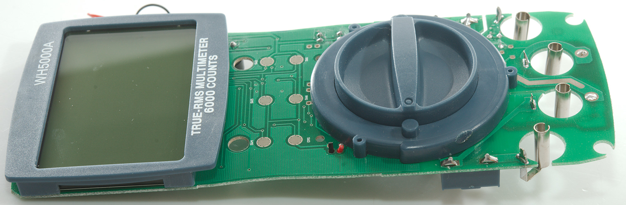
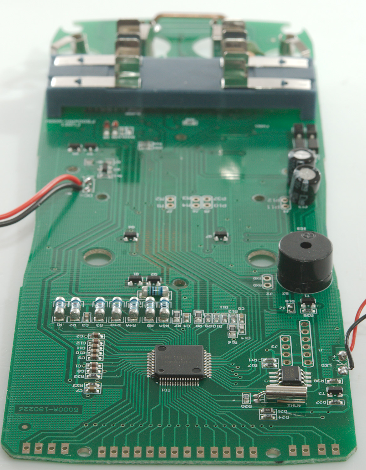
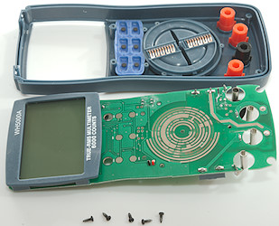
If only the correct two screws are removed, the circuit board looks this way when removed.
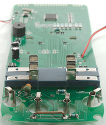
Display is also mounted on the circuit board.
That was another 3 screws.
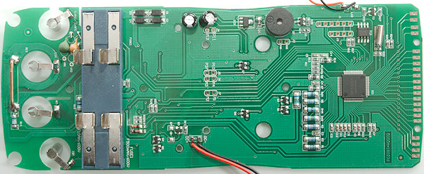
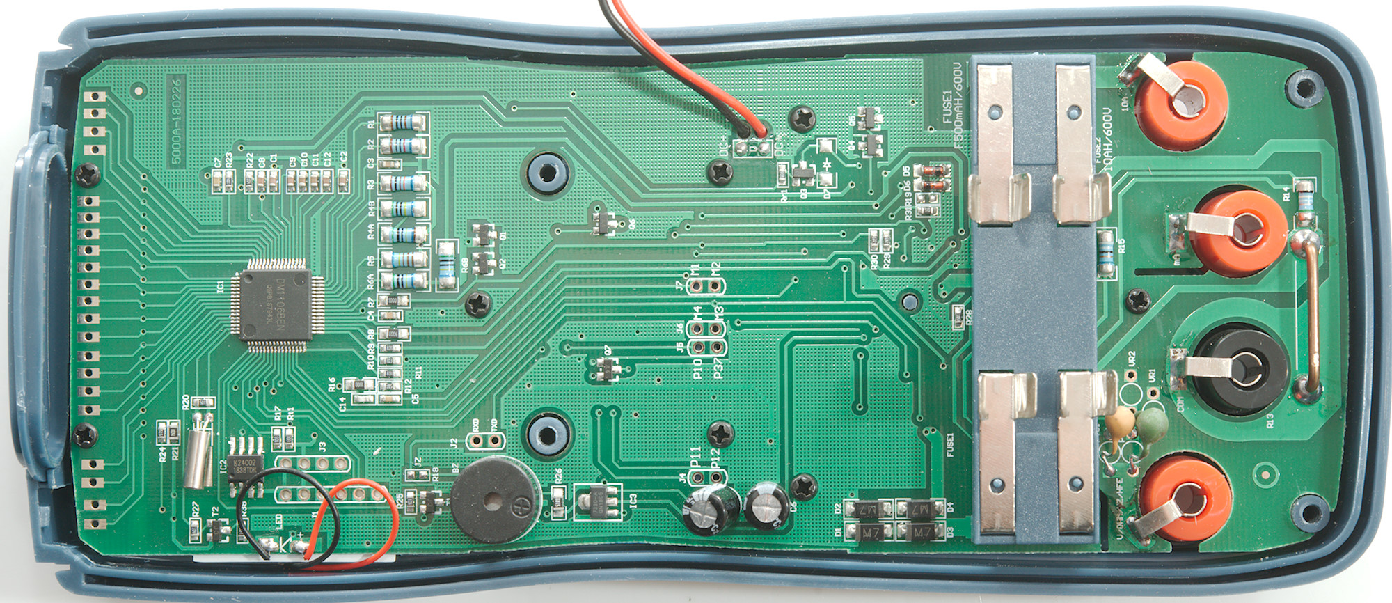
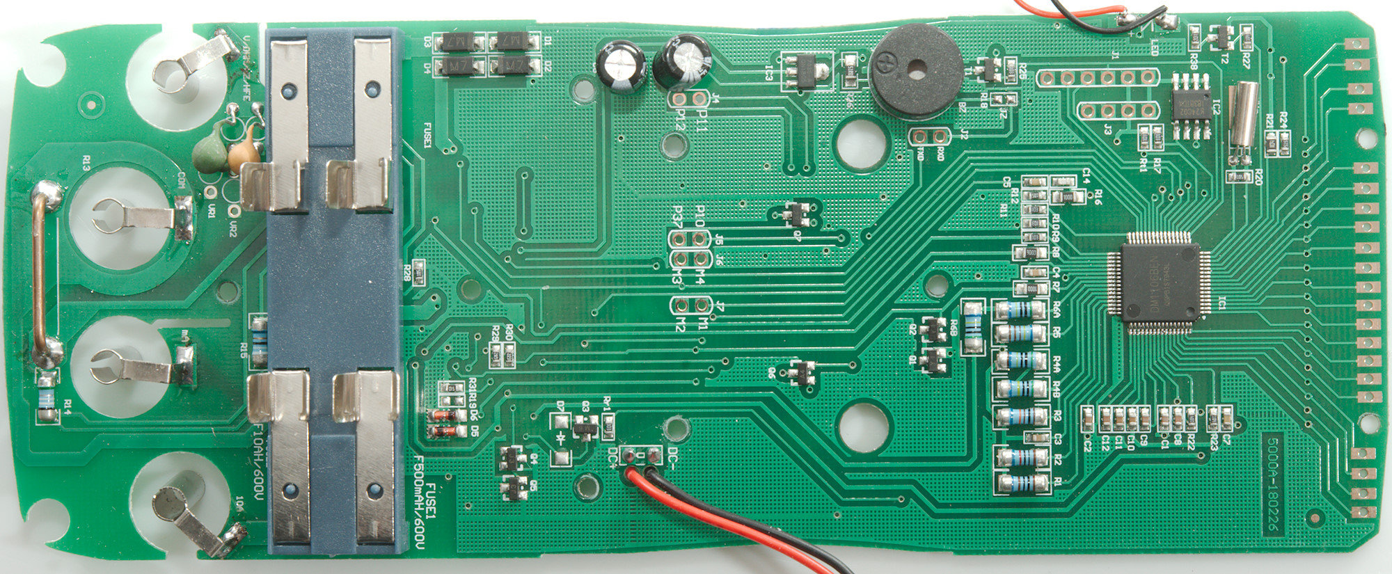
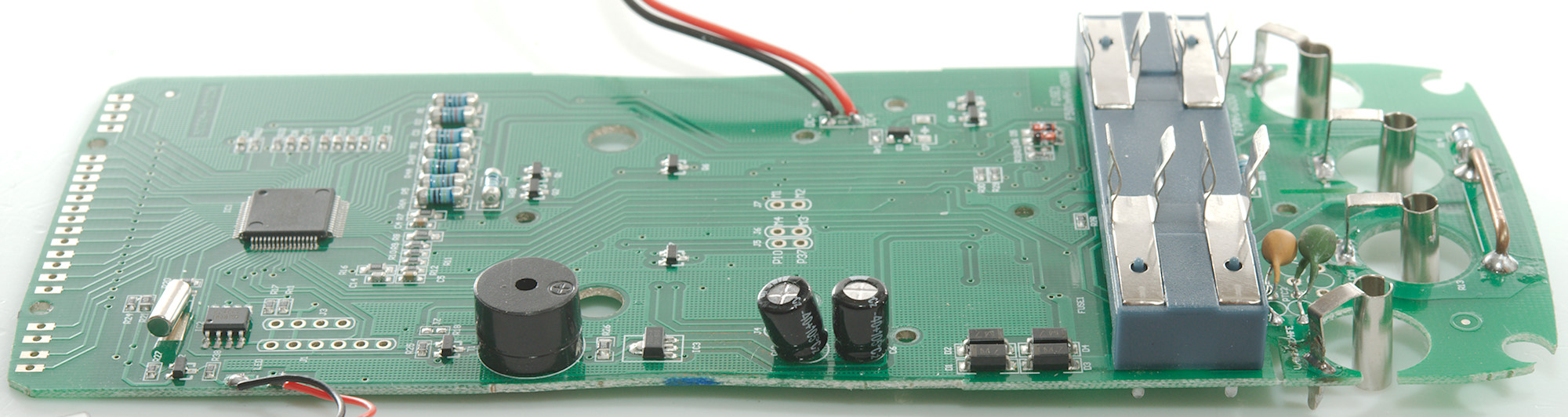
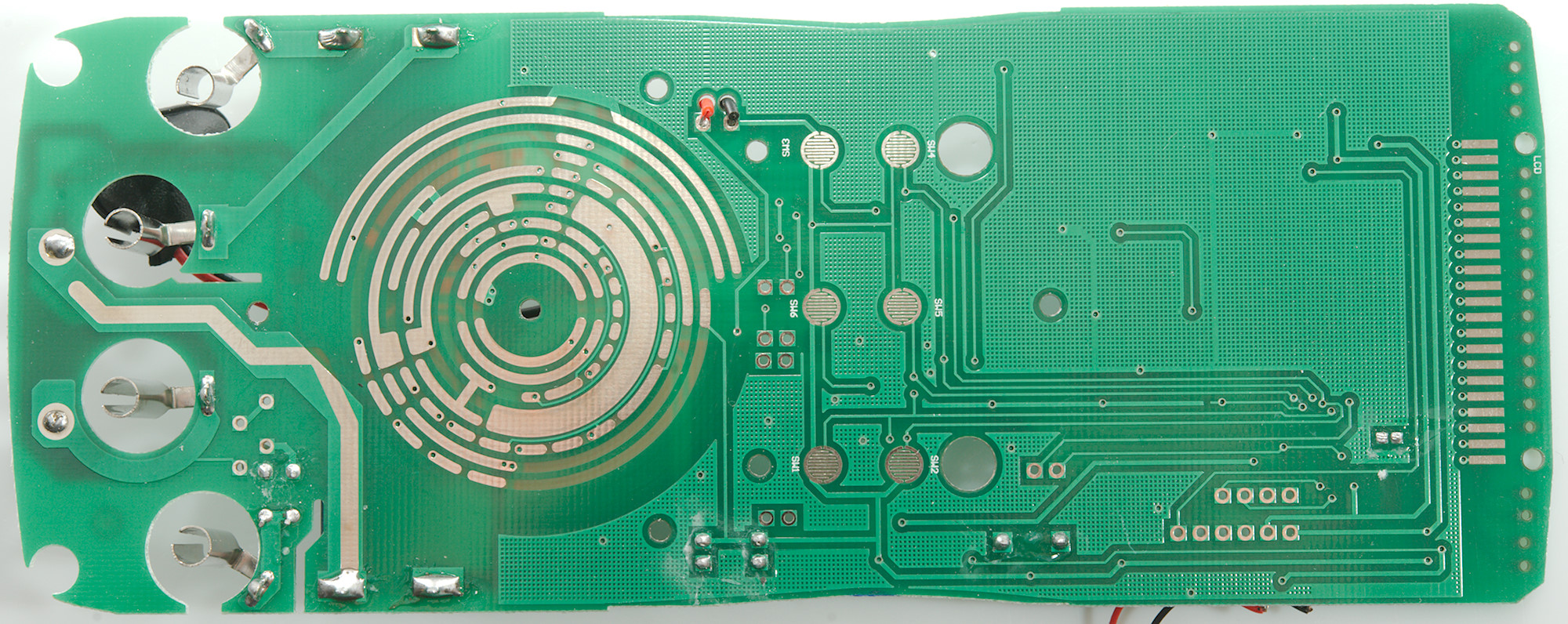
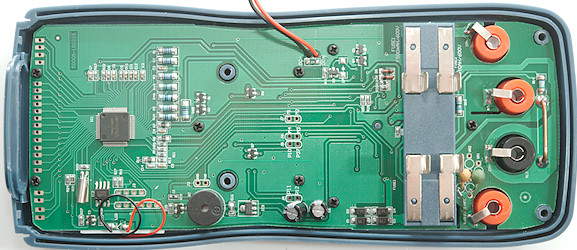
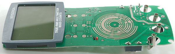
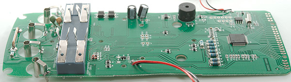
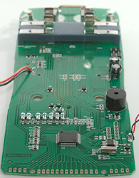
The 10A shunt (R13) is moderate in size, next to is the mA shunt (R14: 0.99ohm) and near the fuses the uA shunt (R15: 99ohm). The uAmA ranges are protected by a fuse and four diodes (D1..D4). Voltage input uses a PTC (PTC1) and two resistors (R6A & R6B: 2x5Mohm).
Ohm and capacitance uses a PTC (PTC2) and a resistor (R8: 900kOhm) for sense input and another PTC (PTC1), a transistor pair (Q1 & Q2) and a series resistor (R7: 100ohm) from the chip for current output. For Hz, temperature and clamp input the same path is used (PTC1, Q1 &Q2, R7). For HFE it is again a PTC (PTC2), but another transistor pair (Q4 & Q5).
The multimeter is, as usual, based around a single chip (IC1: DM1106BEN) and a EEPROM (IC2: 24C02) and uses a 3 volt regulator (IC3: 7330-A) for supply.
Near the PTC's are space for two MOV's in series connected to PTC1 and common. I doubt they would have much effect, MOV's are often needed on both input and some longer distances are required.
This meter had a few issues putting together again, first the small steel balls inside the range switch and then getting the fuse holder to fit the cutouts in the enclosure, when that succeeded all the screws had disappeared (They where found on the magnetic hanger).
Conclusion
The CAT rating is not correct, 600V fuses are not enough for 1000V, input protection is better than some cheap meters, but that do not make it good. The actual input rating is also very confusing.
For hobby use it is fine and can be used on mains voltage from normal mains outlets, it has many ranges and also min/max, but I am missing frequency in voltage and current modes.
Notes
How do I review a DMM
More DMM reviews