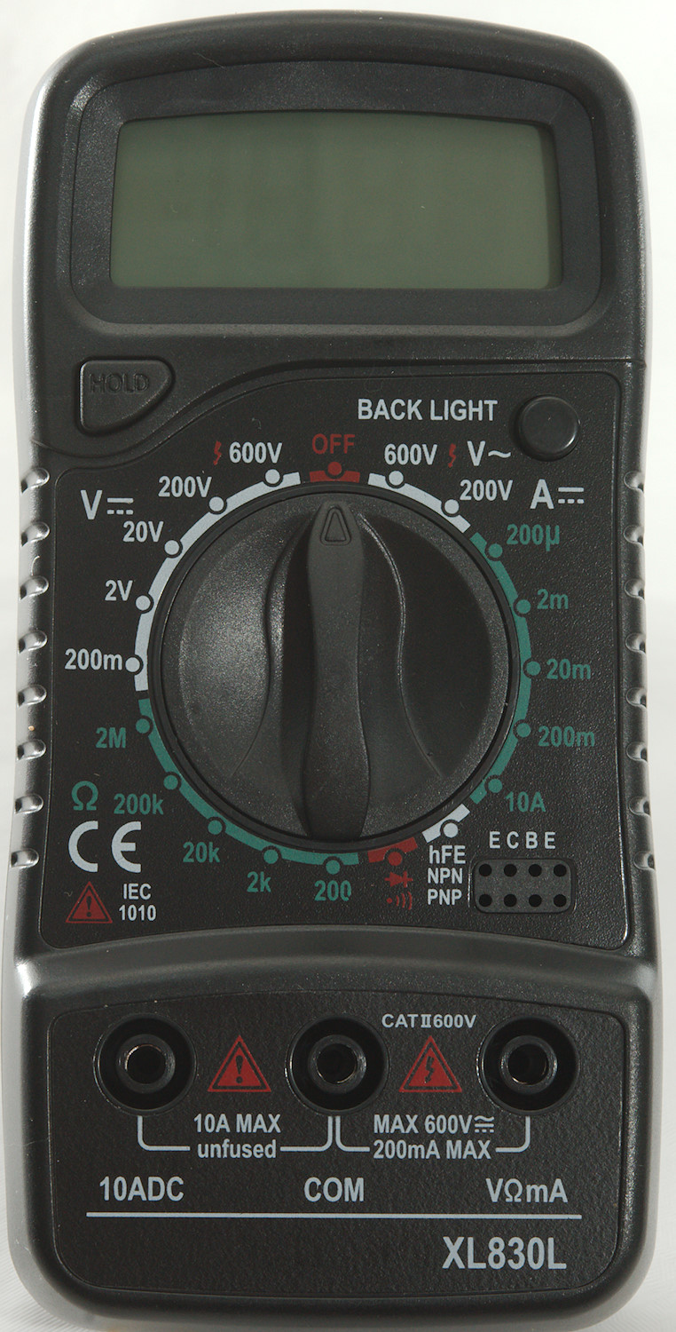
DMM XL830L
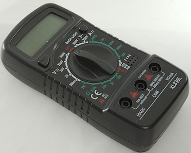
This is a really cheap DMM with manual ranges and a minimum of functions.
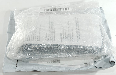
There was no box included with the DMM.
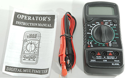
It included the DMM, a pair of probes and a instruction sheet.
The instuction sheet includes specifications for AAC and capacitance, two ranges the meter do not have.
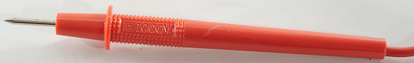
The standard probes are rather tiny.
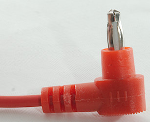
They use 4mm plugs, but they are not shrouded.
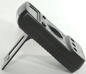
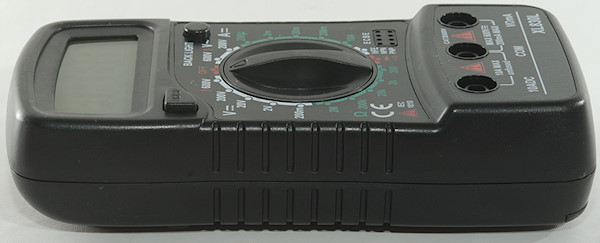
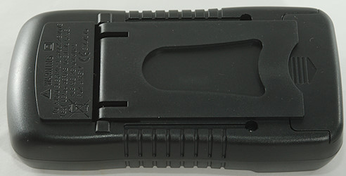
When using the tilting bale the DMM requires two hand to turn the range switch, when laying down it depends on the surface. The meter is very smooth on the back and will easily slide around.
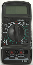
Display
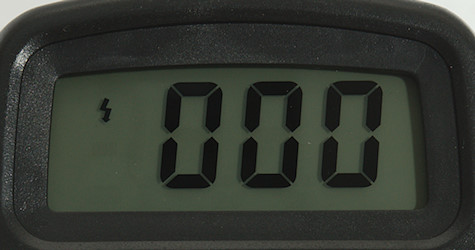
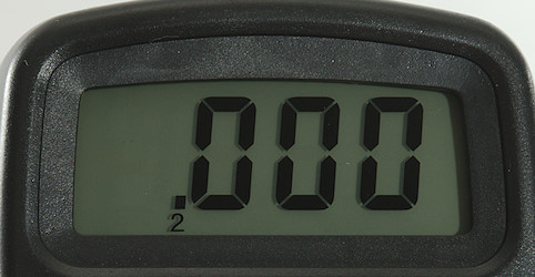
Typical display during usage, it will show the number and what range is selected (i.e. 2 in the picture above).
The lightning symnbol is only shown in the 600V ranges.
Functions
Buttons:
- Hold: Will freeze the display reading, until pressed again.
- Backlight (Round button): Turn backlight on.
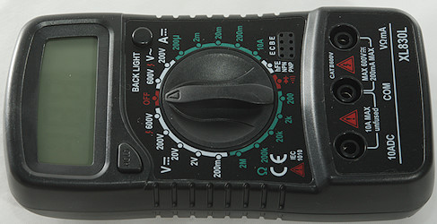
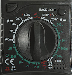
Rotary switch:
- Off: Meter is turned off
- VAC: 600 & 200: AC voltage ranges.
- ADC: 200u, 2m, 20m, 200m, 10A: DC current range
- hfe: NPN & PNP: Transistor tester
 : Continuity and also announced as diode, but it is not.
- Ohm: 200, 2K, 20k, 200k, 2M
- VDC: 200m, 2, 20, 200, 600: DC voltage range.
Input
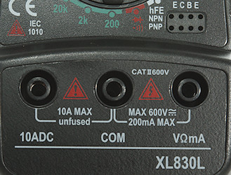
- 10ADC: 10A unfused DC current input.
- CON: The common terminal for all ranges.
- xxx: All other ranges, including mA. It is always problematic when a current range shares connector with a voltage range, if the switch is in the wrong position the (hard to replace) fuse will blow (at least). This will only affect current, voltage will still work.
- ECBE: Transistor tester input.
Measurements
- Volt and frequency
- 5 VAC is 5% down at 5kHz
- Input impedance is 1Mohm on DC also in mV
- Input impedance is 0.5Mohm on AC
- AC range uses a single diode, i.e. DC will show a (wrong) voltage if it has the correct polarity.
- Current
- 10A range will change a few percent at 10A current due to heating.
- 10A range is unfused
- mA range is fused with a soldered fuse.
- Ohm, continuity, diode and capacitance
- Ohm needs about 1.5s to measure 100ohm
- Ohm voltage is 0.3V open in 20k and above ranges and 25uA shorted in 20k range down to 0.3uA in 2M range
- Ohm voltage is 2.9V open in 2k and 200ohm ranges and 3.3mA shorted in 200ohm range and 1.6mA in 2k range
- Continuity is slow (About 400ms).
- Continuity beeps when resistance is below 72ohm.
- Continuity is 2.9V open and 1.6mA shorted
- Diode rnage is same as continuity and it will show ohm
- Miscellaneous
- Current consumption of meter is 0.64mA except 2k, 200ohm and Continuity where it is 3.4mA (Backlight adds a short burst of up to 50mA)
- Backlights fades from the moment the backlight button is released.
- Meter displays values down to 2.7V where it turns off, battery symbol show at 6.8V.
- Readings will increase significantly in value below 6.2V (Shows about double voltage at 2.8V).
- Backlight works down to about 2.6V where it is fairly dim.
- Viewing angle is good
- Display updates around 3 times/sec
- Backlight will fade to off in about 12 seconds.
- Will not automatic turn power off
- Standard probes cannot be fully pushed down, but they do make contact.
- The meter usual need a couple of display update to reach the final value.
- Weight is 135g without assories, but with batteries.
- Size is 138 x 68 x 34mm
- Probes
- Probe resistanse 93mOhm for one.
- Probe wire is fairly soft and thin, the are 58cm long.
I do not believe the specified tolerances, the included manual did not match the DMM.
On 10A range the shunt will heat up and the meter go slightly out of tolerance.
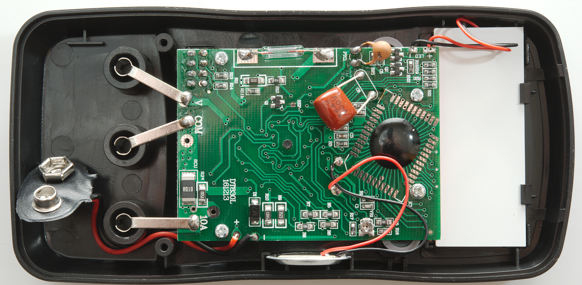
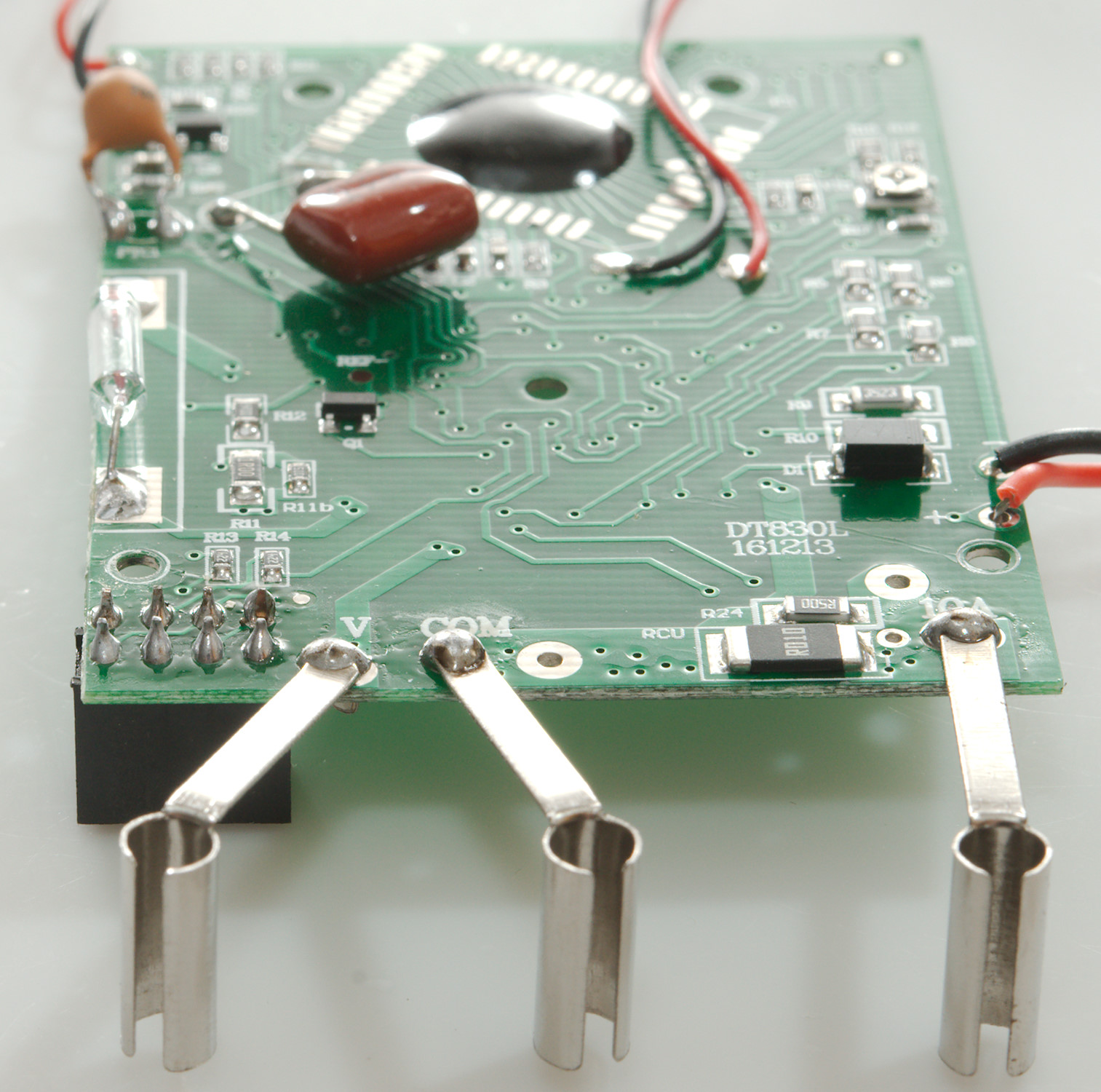
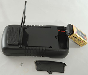
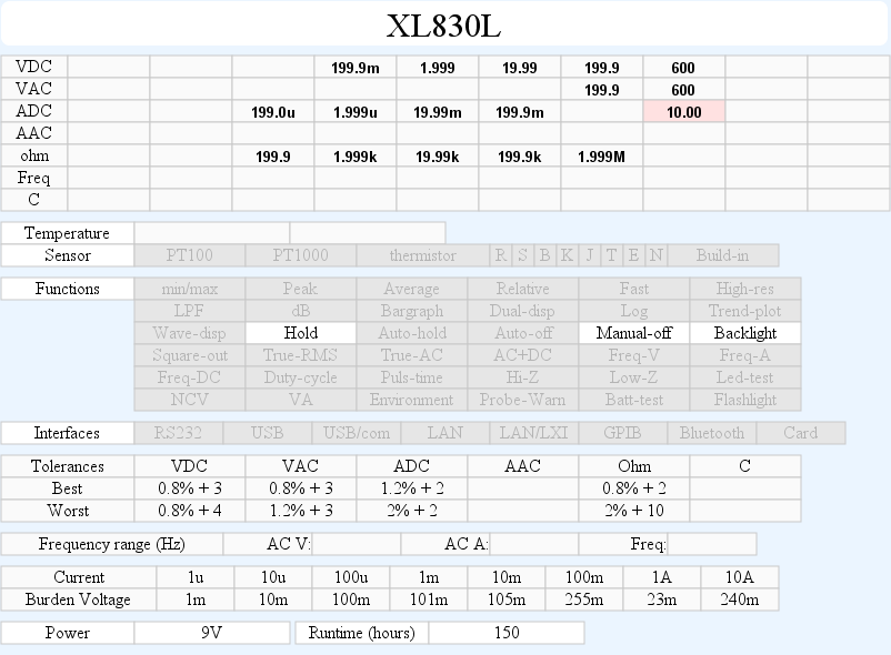
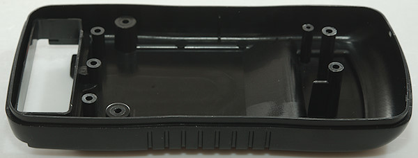
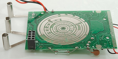
Tear down
Two screws and the back could be removed, I did also remove the battery cover due to the battery and battery connection wire.
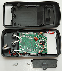
Four more screws to remove the circuit board, the buzzer and the backlight module. The LCD display is the tinted glass that still is in the meter.
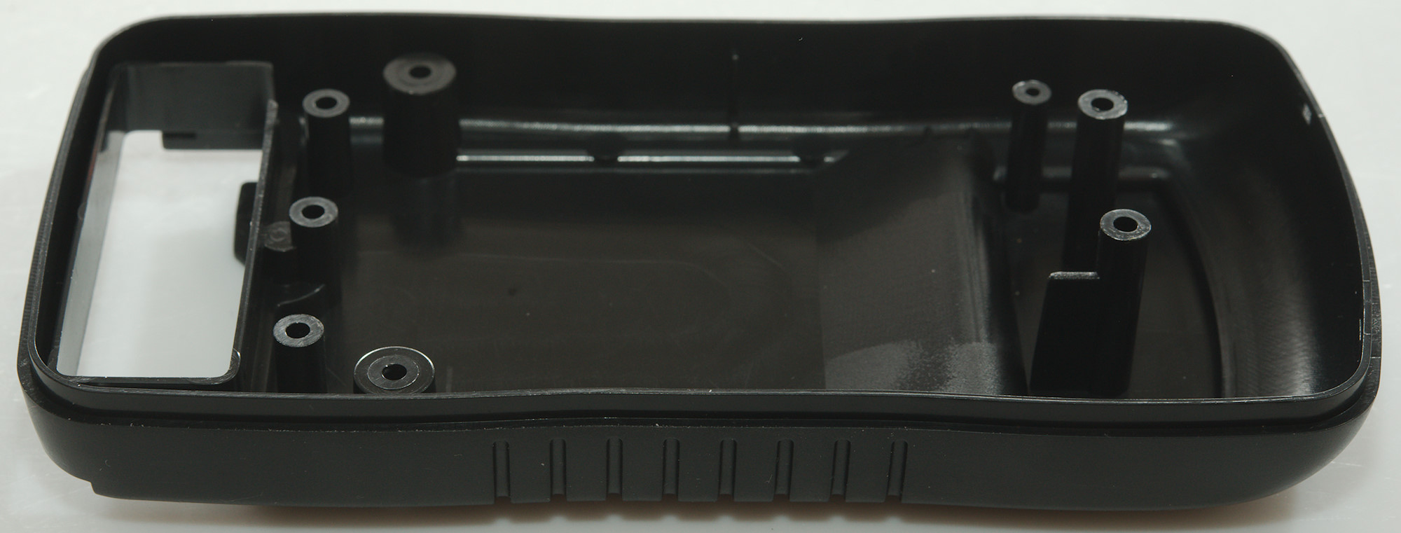
There is not much support of the input terminals to see here. The buzzer is mounted in the box and connected with two wires, there are also wires to the backlight module.
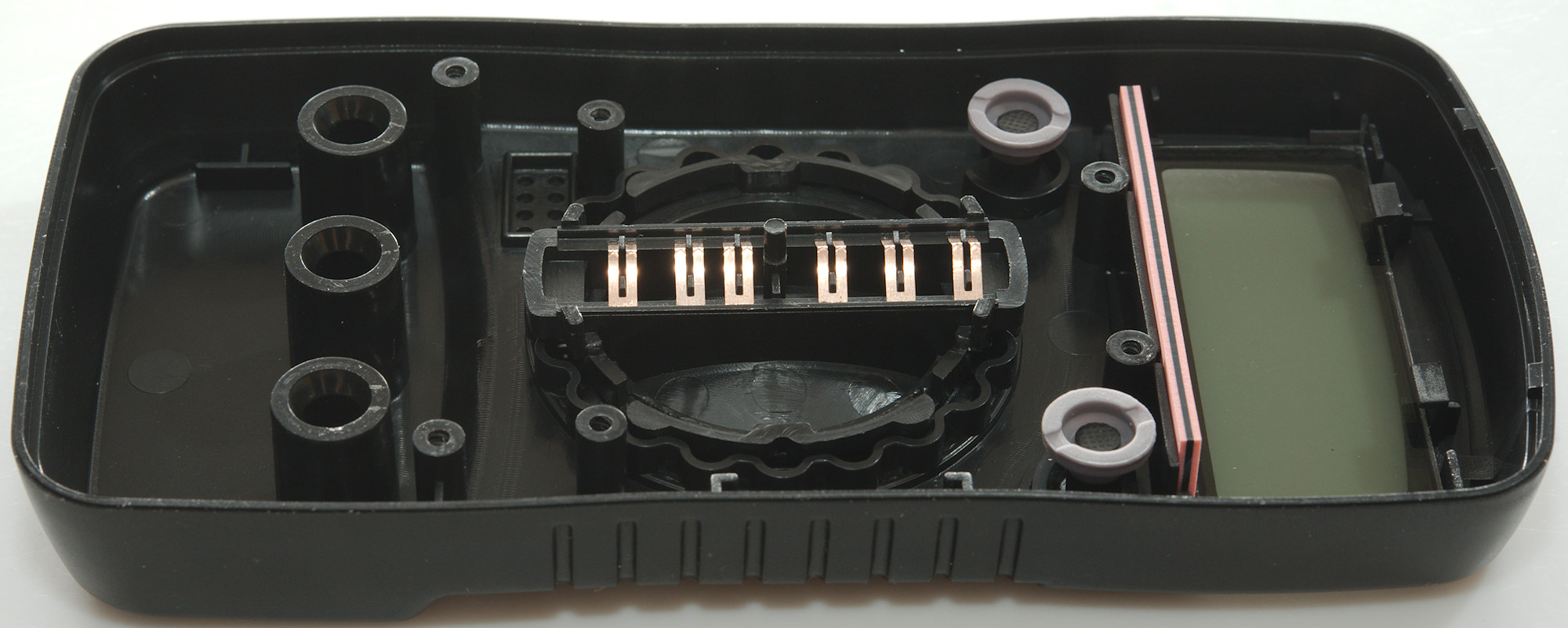
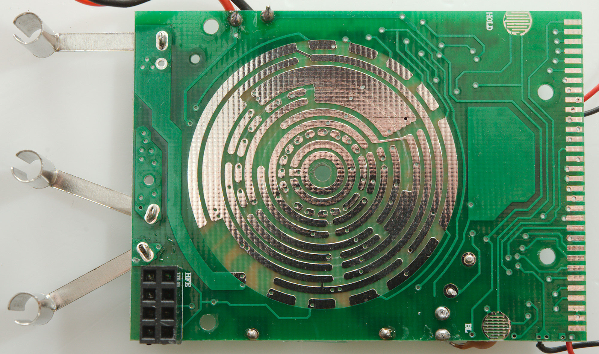
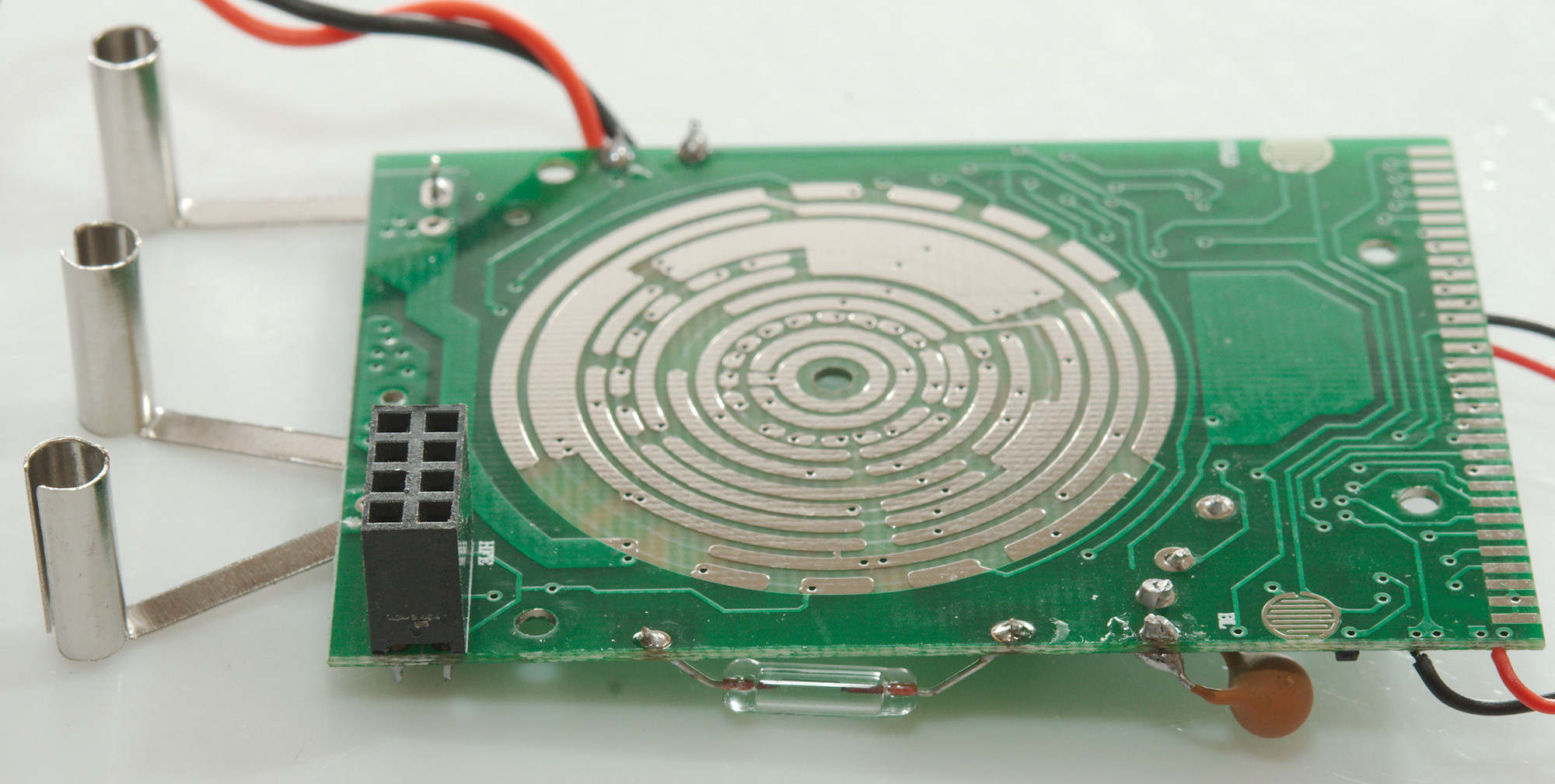
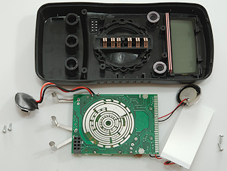
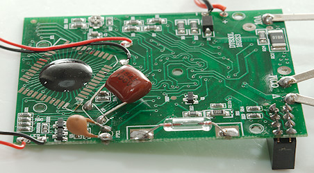
The support for the input terminals is here.
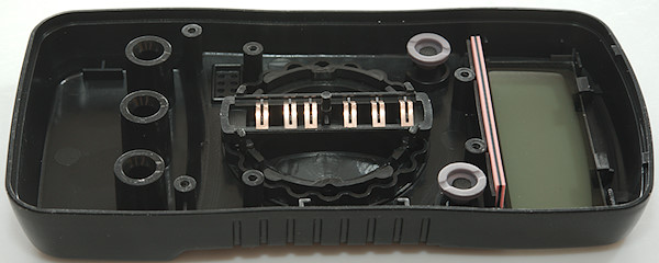
The zebra stribe that connects the display to the circuit board can be seen here (The pink part) and the two buttons.
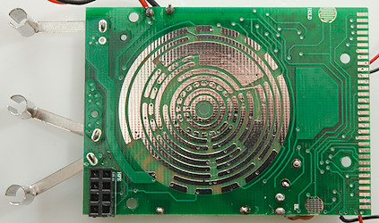
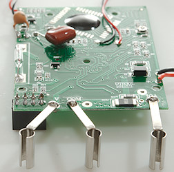
One this side of the circuit board is the range switch, the two buttons and the transistor tester socket.
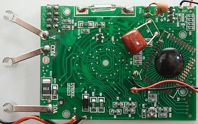
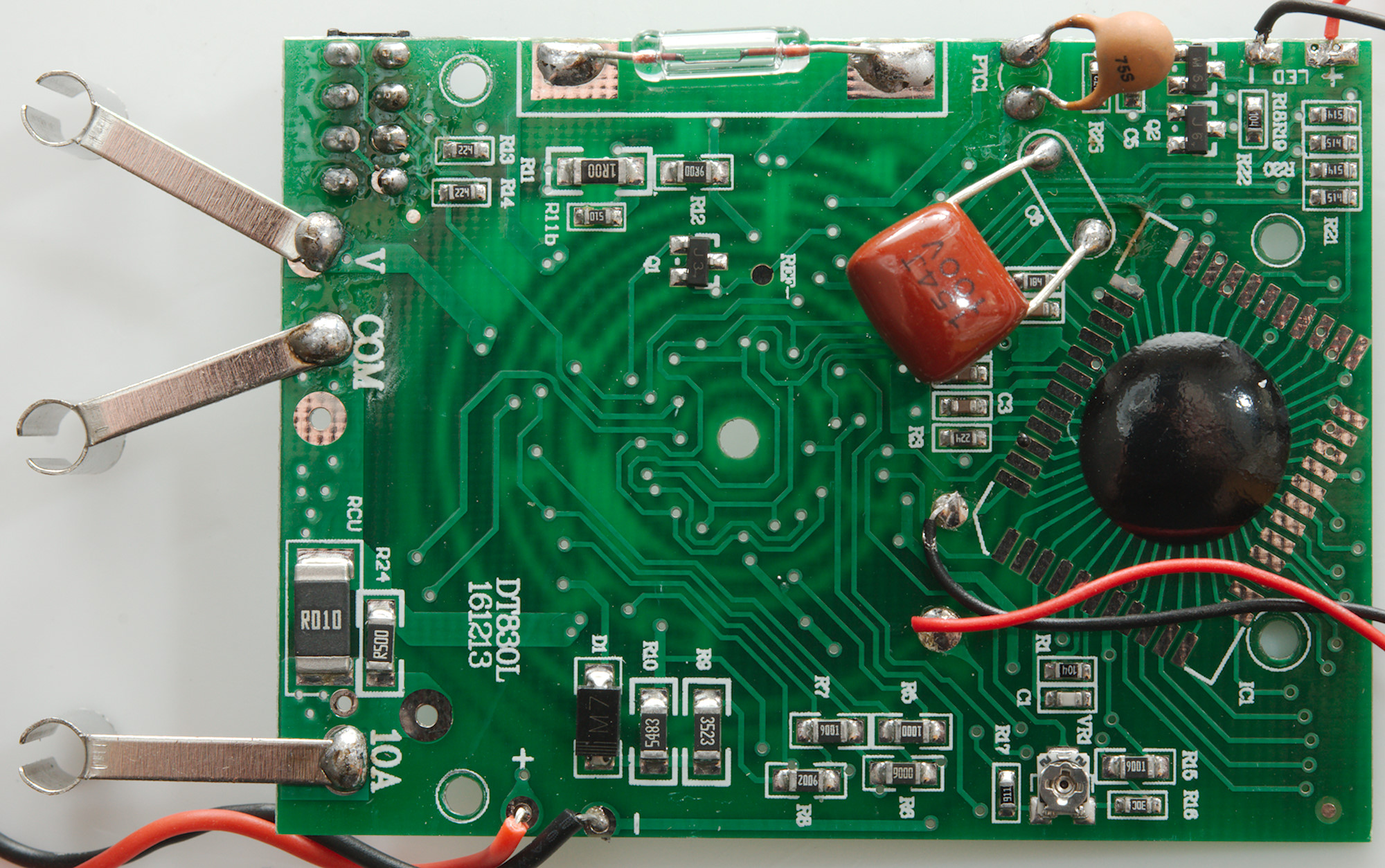
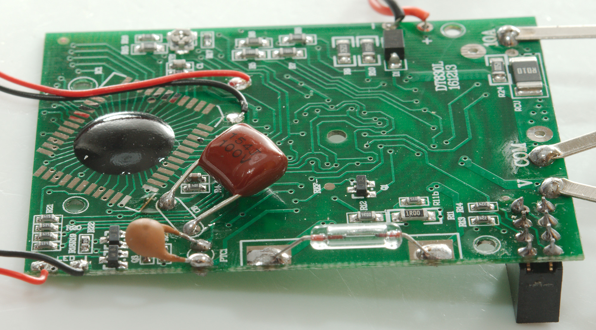
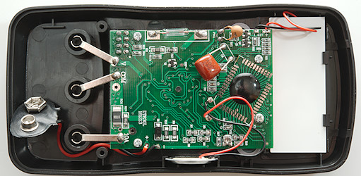
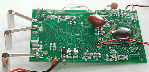
This is where everything is, the DMM chip is a COP (Chip on board, i.e. chip mounted and bounded directly on circuit board, then sealed).
Being manual range this meter probably has resistors for each range.
RCU & R24: Shunt for 10A (On most meters this is a short wire). R11: Current shut for 200mA, R12: Current shunt for 20mA, R6: 2mA shunt for 2mA, R7: shunt for 200uA.
In DCV input goes to R10 and in ACV input goes to D1, this is the reason for only high AC voltage, the meter uses a normal diode for rectification.
The PTC1 is input protection. Q3 is for driving the backlight.
The fuse is soldered in and is only used on uA and mA ranges.
There is only a single trimmer, this means the precision depends on how precise the parts (resistors) are.
Conclusion
The CAT rating is fairly low, but I doubt it is valid, because the meter is unfused and lacks protection.
This is a simple and cheap DMM without any real input protection and with only a few ranges. This may be enough for some applications, but keep it away from mains voltage.
Calibration is generally good, that means many ranges are within 1 to 3 count.
Notes
This meter exist with many different names on it and small variations in functions.
How do I review a DMM
More DMM reviews