USB meter: USB Detector
Official specifications:
- Compact, can be displayed voltage and current simultaneously on the same screen
- End of the input, output at both ends
- output( Dual function):Data communication functions,Charging voltage output
- It uses sophisticated SMT process, so good consistency
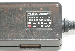
- Supply voltage:3.2V-10V
- Test Current:0-3A(up to 10A)
- Working current:<20mA
- Display:0.28"LED.(red)
- Size:69×26×19 mm
- USB extension cable:>120mm
- Measuring rate:<500mS/times
- Accuracy:1%
- Min. supply voltage:3.2V
- Max. supply voltage:10V
- Operating Temperature:-10~+65
- Humidity:10~80%
- Working Pressure:80~106kPa
- Sunlight:No direct exposure
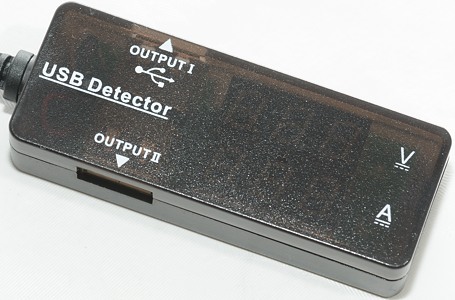
I found this unit on Ebay at a dealer called tool-edge.
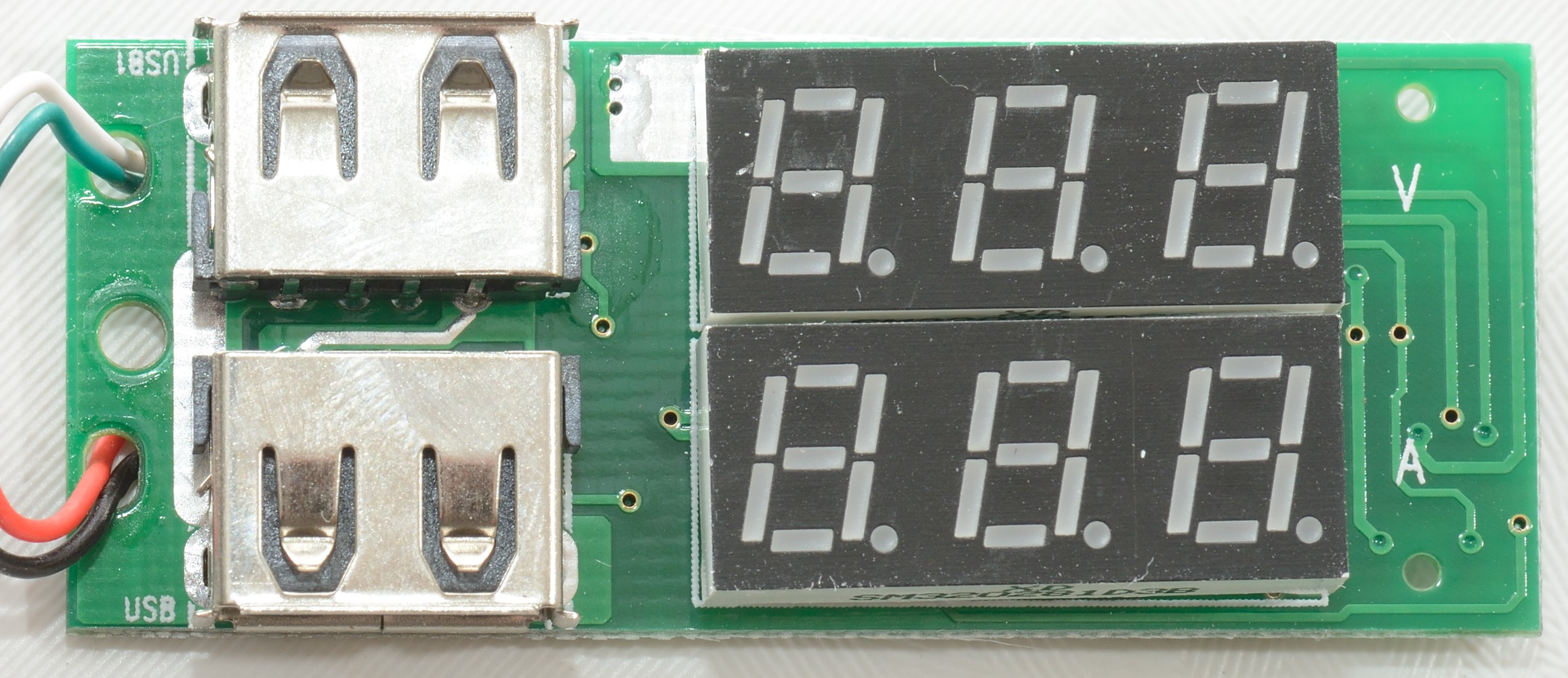
How does it look
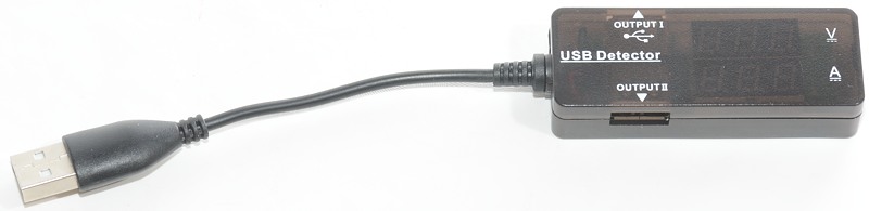
The usb input is on a short wire. This can make it easier to connect it in some cases, but will add some extra resistance.
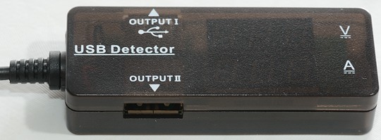
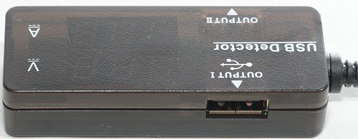
The usb meter has two outputs, but the display is common.
It might be possible to find different versions of this usb meter.
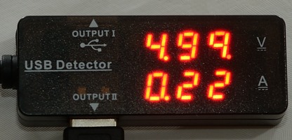
It has two displays and shows both voltage and current simultaneously. The reason for the two different 9 is because there is a faulty segment in the display.
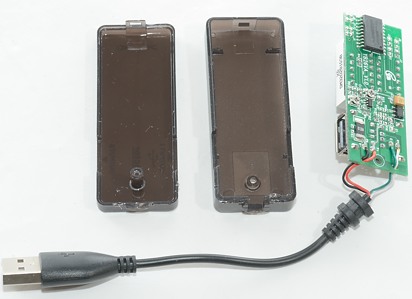
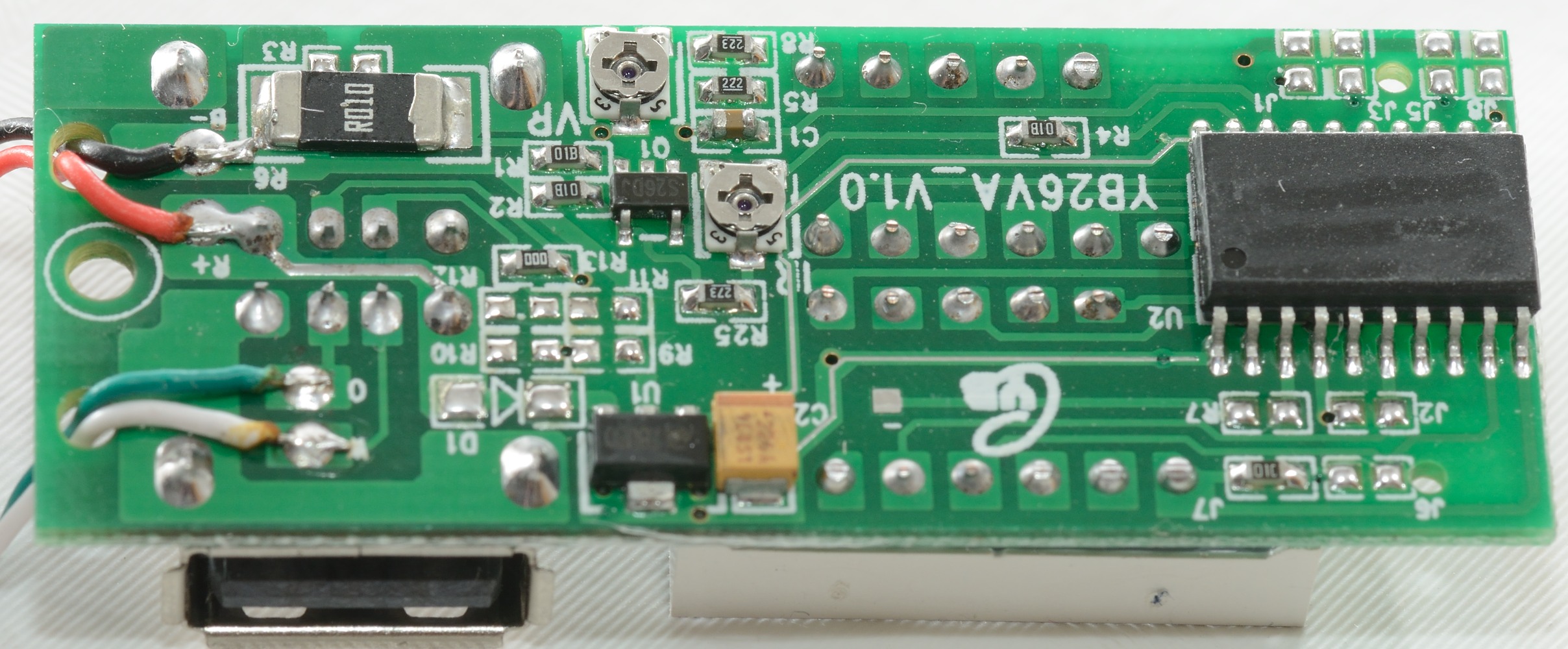
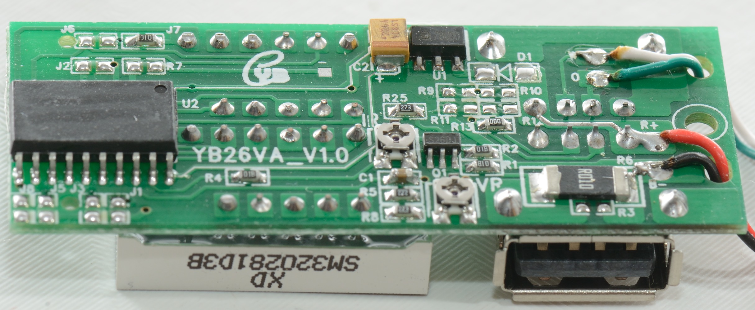
It is easy to open, only one screw.
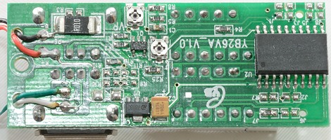
The sense resistor is 10mOhm (0.01ohm), it is marked R010. That is the reason for the low resistance
The points marked J1, J2...J8 on the PCB is probably used to select the different models of this device.
It is also possible to mount parts for either DCP or Apple coding on Out2 (R9..R13).
The reason it is rated for up to 10 volt is because U1 is regulating the voltage for the microprocessor and display.

Another interesting detail is the IR and VR trimpots, they makes it possible to adjust/calibrate the readout (Mine is correct now).

Measurements
Out 1 and Out 2
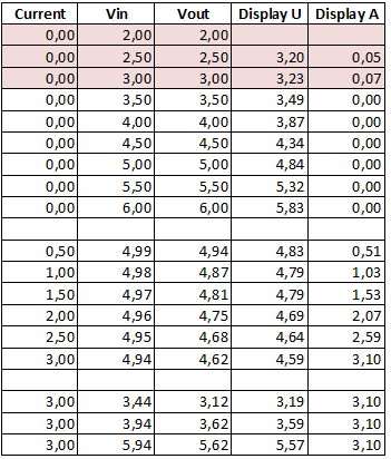
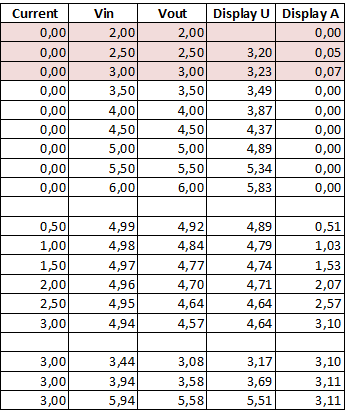
Some of the difference between out1 and out2 can be due to contact resistance.
- The readout is not very precise and not within the specified 1%
- The usb meter uses 20mA current
- The internal resistance is about 0.1ohm for out A (This includes both connectors).
- The internal resistance is about 0.13ohm for out B (This includes both connectors).
- Out1 is connected to the usb input connector and works fine for data transmission.
- Out2 is coded as a usb charger (DCP)
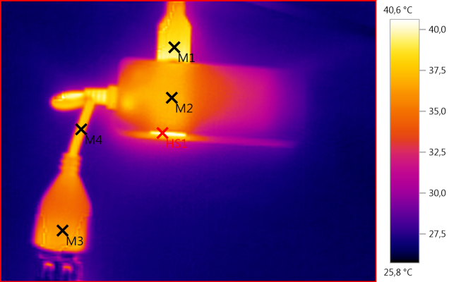
M1: 39,0°C, M2: 37,1°C, M3: 36,2°C, M4: 37,5°C, HS1: 40,6°C
The usb meter do get warm after 1 hour, but the display reading do not change significantly.
The cable has some resistance and do heat up.
Conclusion
I like that the usb meter has both voltage and current display simultaneously and also that the internal resistance is also very low.
But the precision is way to low making the device unuseable for voltage measurement and with the missing segment, it looks like this unit has not been tested/calibrated at all.
For people that can open it and do a calibration, it might be a good device.
Notes
How do I make the test