LCR tester Peak LCR45
For a "simple" tester this device looks fairly expensive, but compare to professional test equipment it is fairly cheap.
And it is not that simple when measuring resistors, capacitors and inductors tester, it has a typically accuracy of about 1.5% according to the manual.
This is done with well defined frequencies and measuring of phase and amplitude.
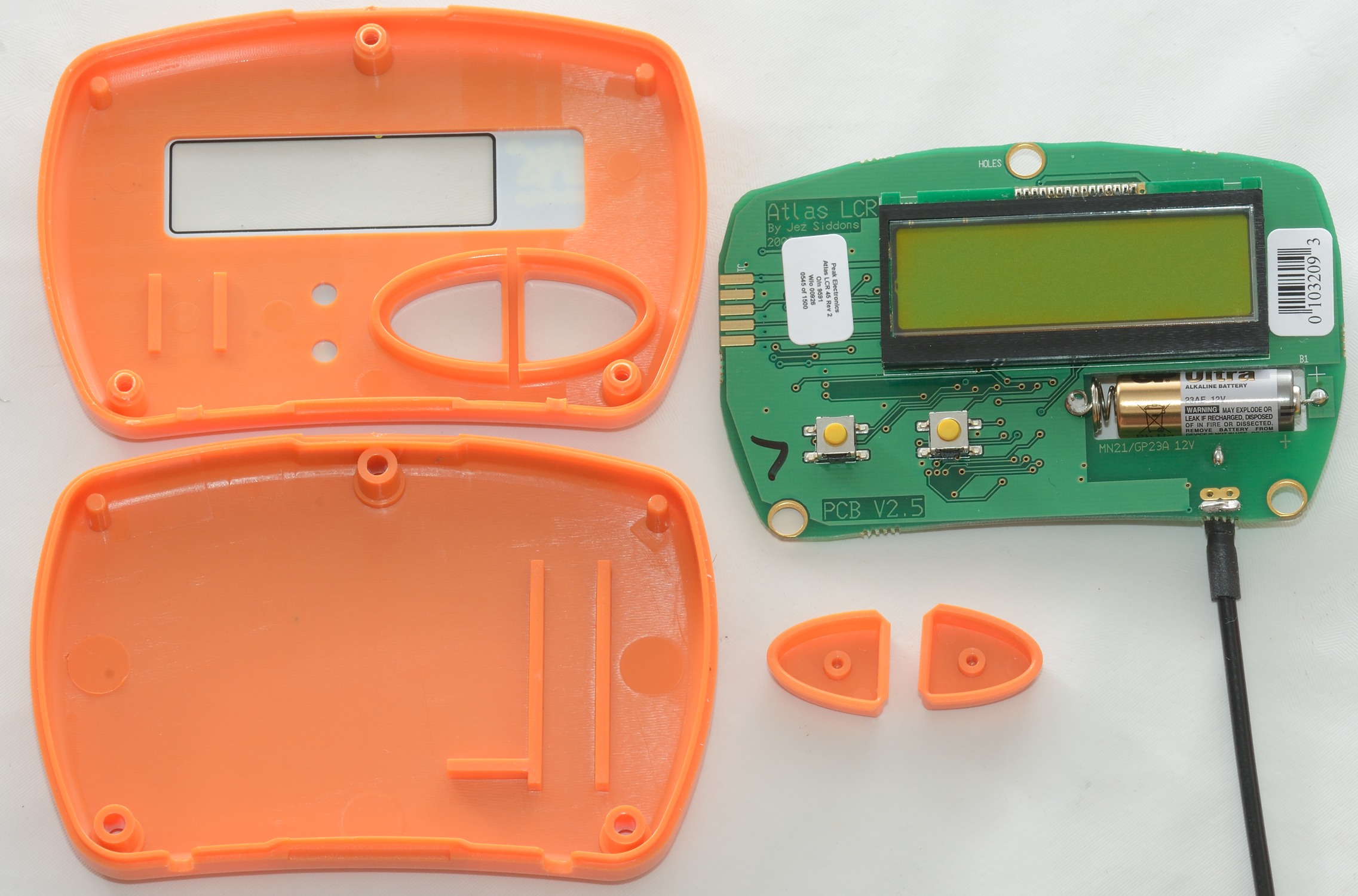
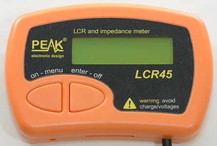
How does it look
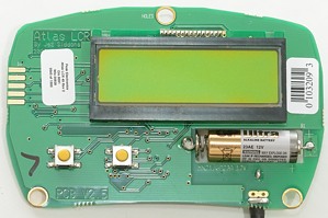
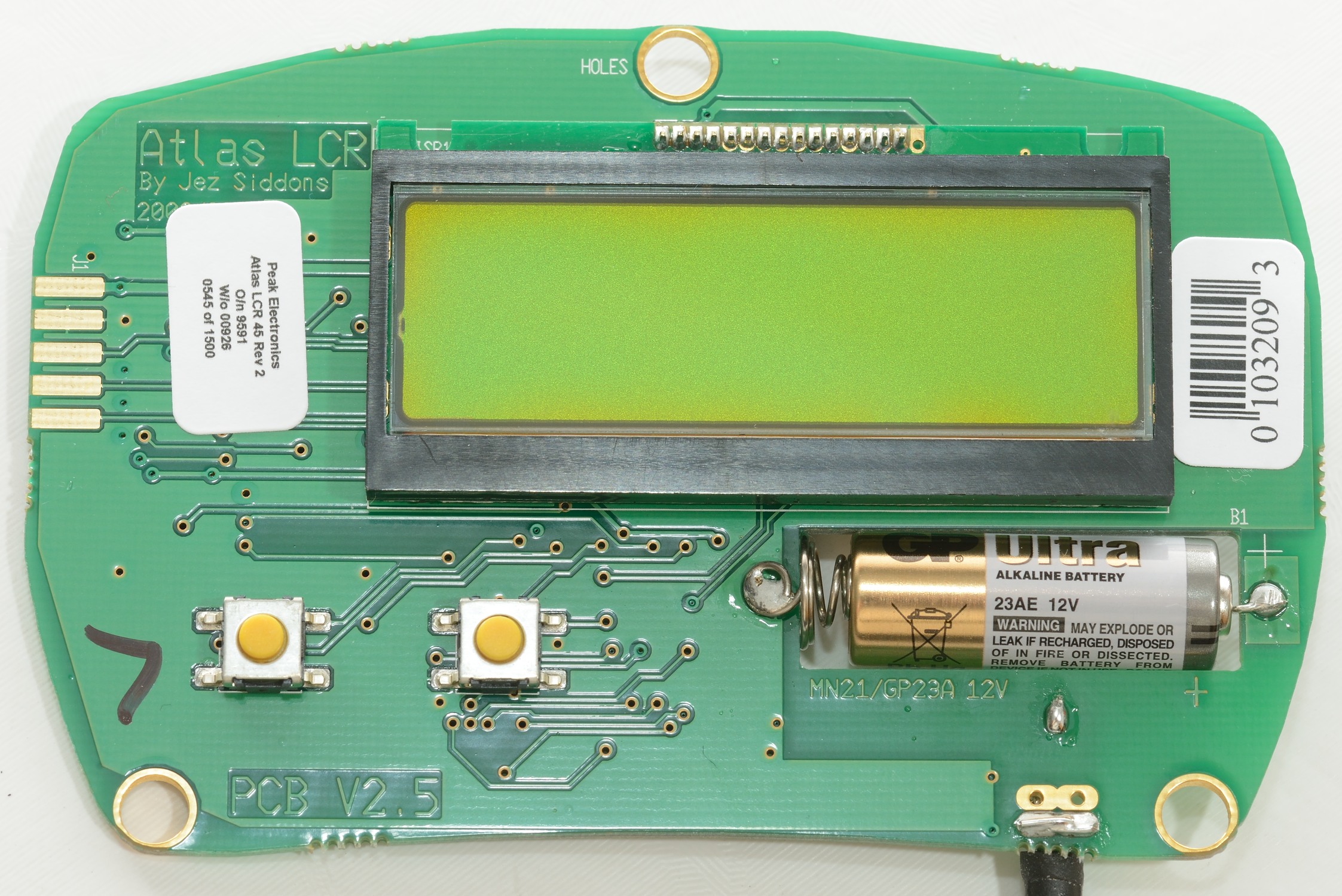
There is not much on the topside, only the display and two buttons.
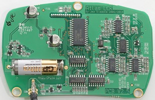

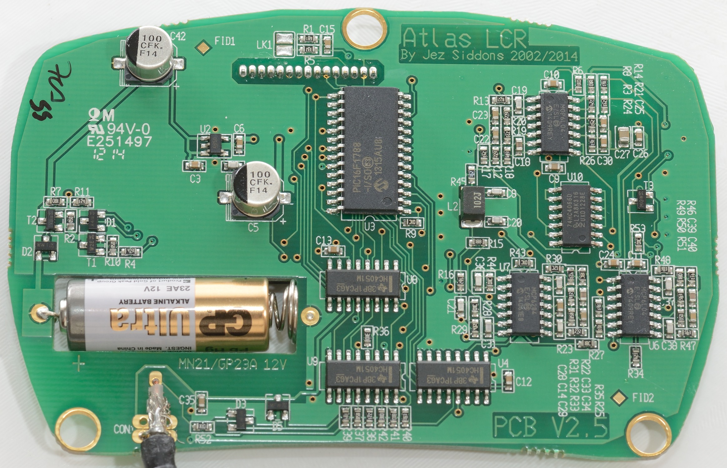
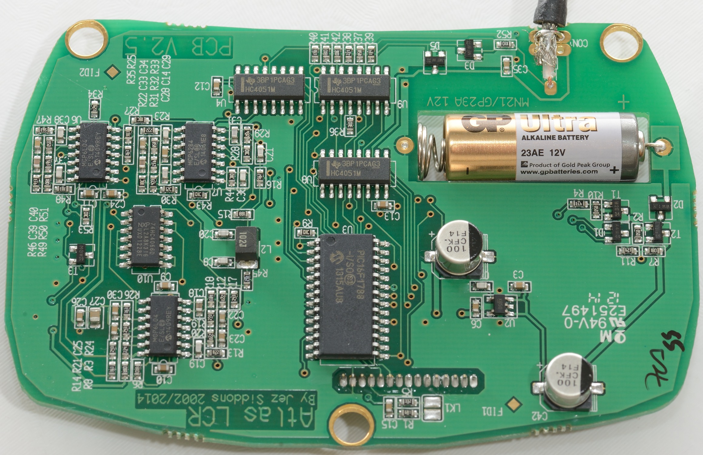
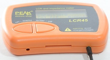
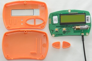
All the electronic is on the bottom. The device generates a fairly clean sinus tone at 1kHz, 15kHz or 200kHz for measuring components.
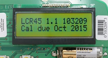
It do keep a calibration date in the internal memory.
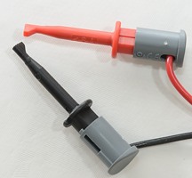
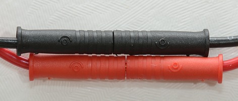
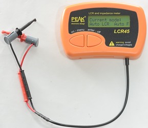
The tester is deliverer with two hooks for component connection, but they are connected with plugs and can be replaced.
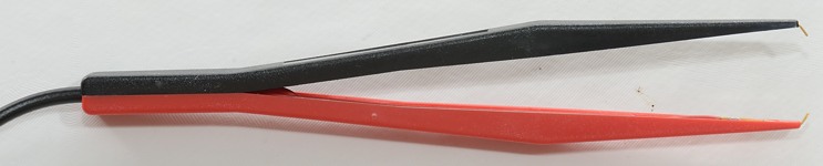
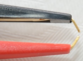
For use with smd components this tweezers can be used.
When replacing the hooks, it is a good idea to do a new zero calibration.
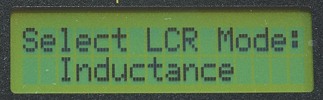
When testing component the tester will usual select component type and frequency by itself, but it can be overridden with a manual selection.
The possible frequency selections are: DC, 1kHz, 15kHz, 200kHz, in the manual a chart shows what component values each frequency can be used for.
Resistors
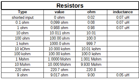
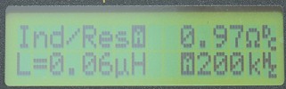
With small resistances the tester cannot decide if it is a small inductor or a resistance and will show both values.
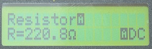
When the resistor get larger and the inductance is low the component will be identified as a resistor.
Capacitors
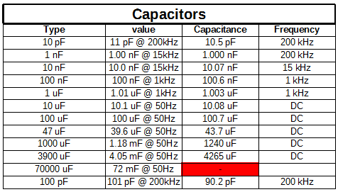
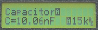
With this capacitor the tester has decided to use 15kHz as test frequency.
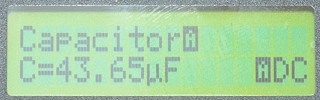
The tester only measures capacity on capacitors, it will not measure ESR.
Because this capacitor is fairly large it is using DC for measuring the capacitance.
Inductors
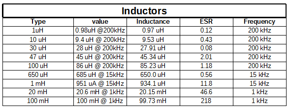
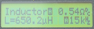
More inductance and not much resistance, this is a inductor.
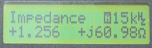
Every time the tester is using AC for measurement it is possible to select between a couple of displays, this is valid for all supported component types. First the impedance that shows the component value as complex resistance.
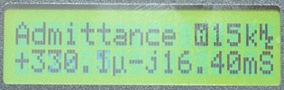
The admittance shows complex conductance.
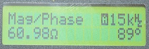
And finally the magnitude and phase angle.
All 3 displays shows the same value, but presented in different ways.
Diodes
Not supported
SCR (Thyristors) + Triacs
Not supported
BJT (Bipolar junction transistors)
Not supported
FET (Field effect transistors)
Not supported
IGBT (Insulated gate bipolar transistor)
Not supported
Voltage regulators
Not supported
Technical details
The tester uses up to +/- 1 volt and +/- 3mA when testing
It uses a small 12 volt battery and has a average current consumption of about 4mA.
When turned on it is possible to measure multiple components without any button presses.
Conclusion
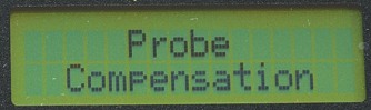
This tester can only do resistors, capacitors and inductors and uses fairly well defined test conditions. It does also have a specified precision. This makes the values from this tester more reliable than from the cheap testers, but the price is also considerable higher. The probe compensations also makes it possible to get fairly good handling of small values.
For sorting a couple of components this works fairly fast, both for smd (With smd accessory) and for leaded components.
Notes
About the testing of testers