Test of DC-DC 7A 9-60V to 3-32V
Official specifications:
- Input Voltage: DC 8V~60V, Recommended to use within 55V
- Output Voltage: DC 3V~32V Continuously adjustable
- Output Current: Max 7A (Recommended use within 5A, Please pay attention to heat dissipation.)
- Accuracy: 1%, the voltage three bits display, the current two bits display, the unit is "A".
- Input Anti-reverse Protection: Yes
- Short Circuit Protection: Yes
- Conversion Efficiency: Max up to 95%
- Load Regulation S(I): <0.8%
- Voltage Regulation S(U): <0.8%
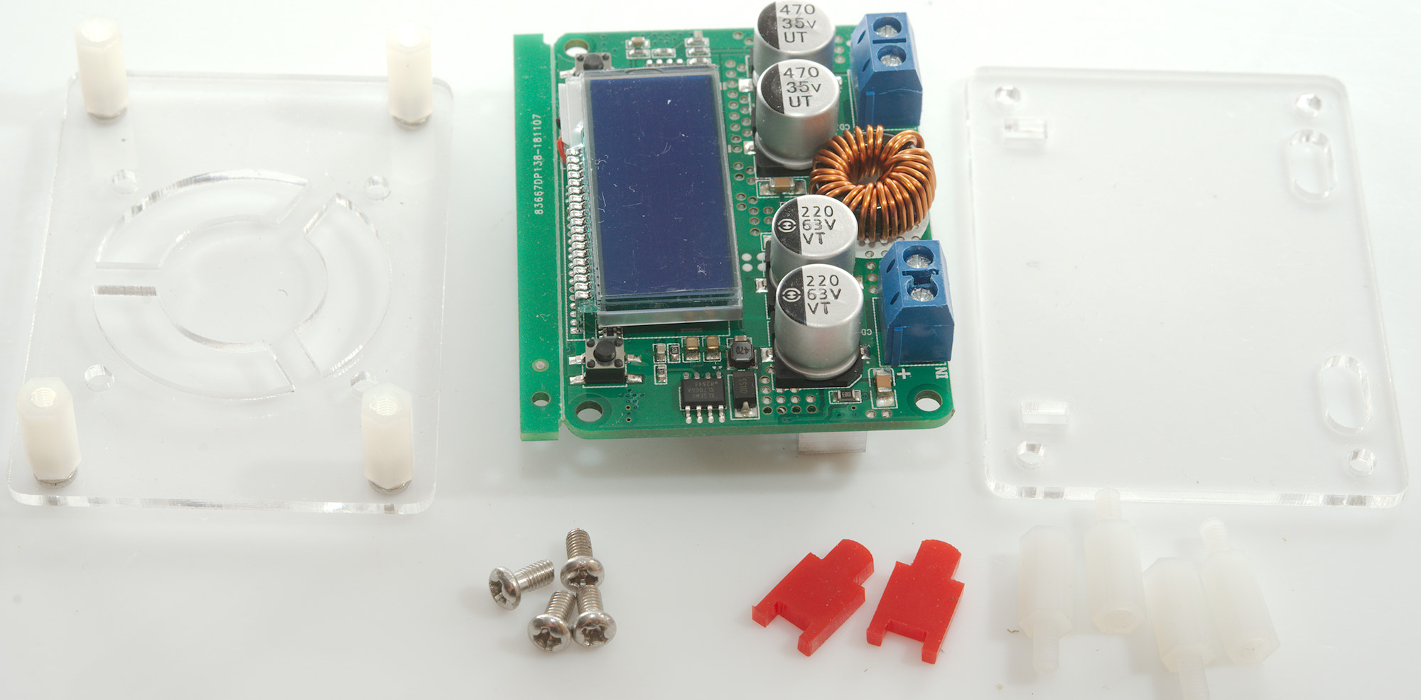
- Size: 62 x 44 x 18mm
- Weight: 45g
I got this module from ebay dealer: best-for-sell
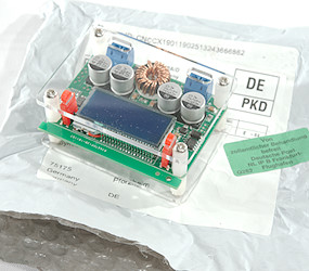
The module arrived in a anti static bag.
Testing
- Minimum unloaded voltage: 3.01V
- Minimum loaded voltage at 3A: 2.65V
- A button click is about 0.03V adjustment.
- Voltage settings are remembered during power off.
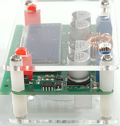
- Display shows actual voltage and current
- Auto repeat is slow to stop.
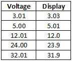
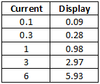
Current and voltage readouts looks precise, it is possible to adjust them.
For all my test curves see here.
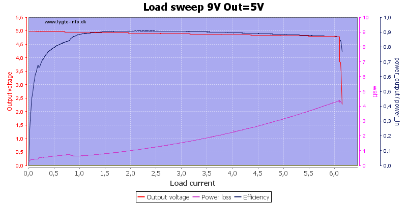
With 5V out and 9V in the converter can deliver about 6A with a loss of 4W. Output drops a bit when load increases.
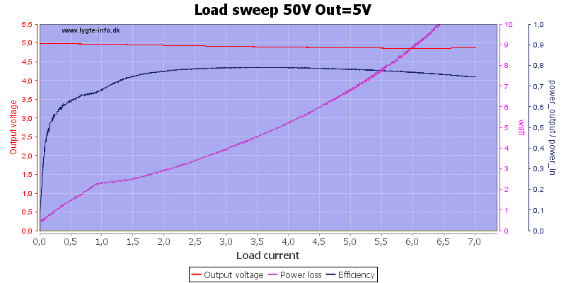
With higher input voltage the output current increases slightly (My test is limited to 7A), but the power loss increases greatly. During one of these tests I saw a discolored LCD due to heat.
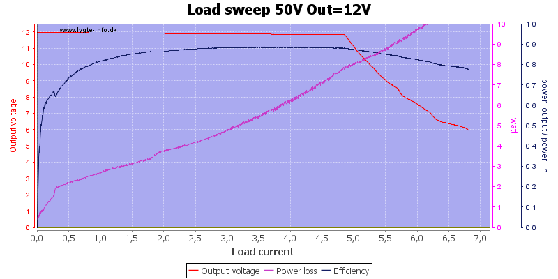
Increasing the output voltage limits the delivered power, here the current is down to about 4.8A and the power loss is very high.
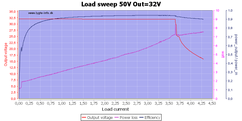
Increasing the output voltage to maximum, reduces the maximum current to about 3.7A, with less voltage to drop the power loss is lower.
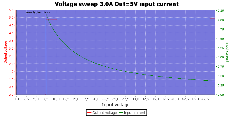
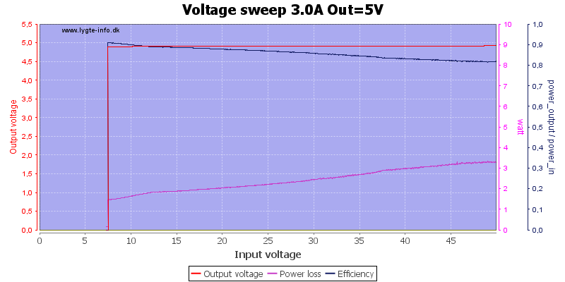
With 5V 3A out it works nicely with any input voltage from about 8V and up. The efficiency is best with low voltage difference.
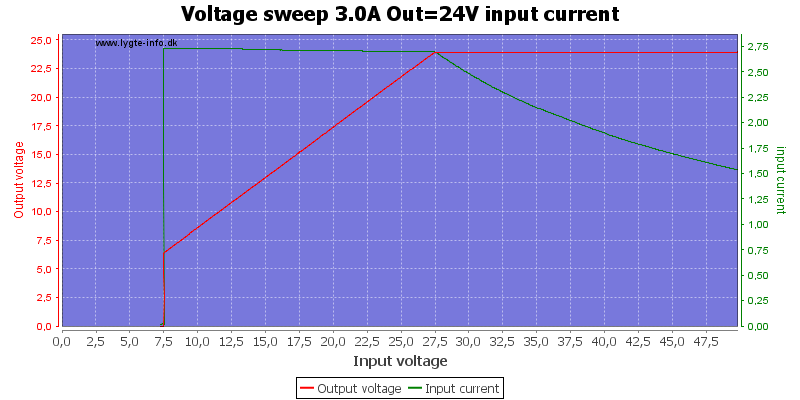
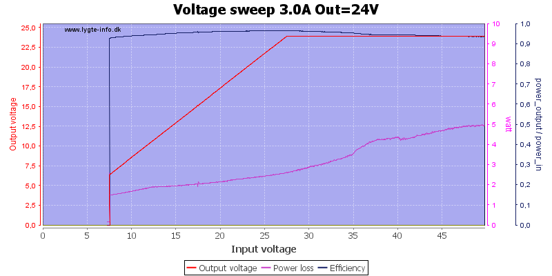
With 24V out the efficiency is high, but it need about 27V to deliver 24V
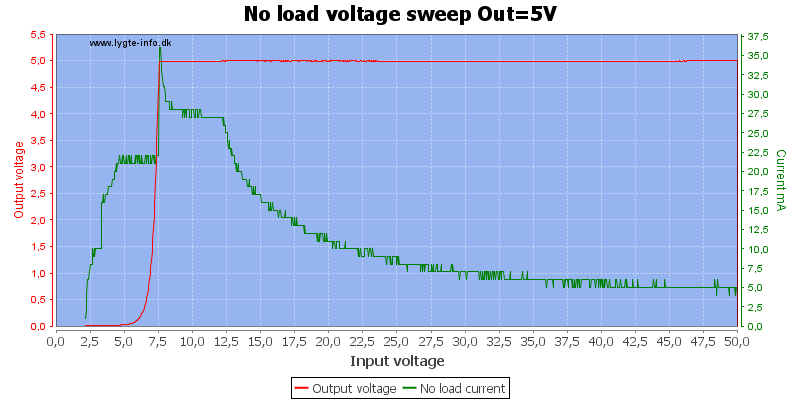
With low output voltage the idle current is fairly low when the input voltage is high.
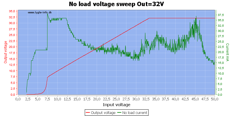
But with higher output voltage the idle current will increase.
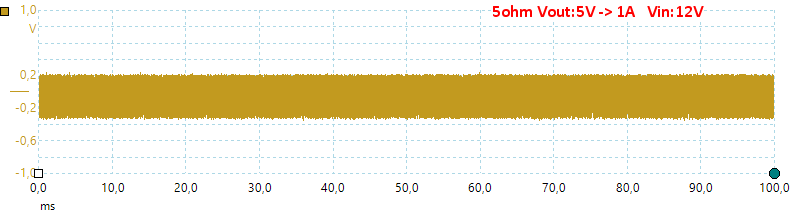
The noise on the output is fairly high, even at moderate loads or unloaded. This is the 200kHz switcher that is a bit low on output filtering.
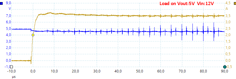
Turning a load on do not change the voltage much.
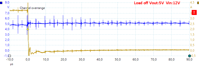
But turning it off makes the voltage jump a bit, with higher input voltage the output jumps more.
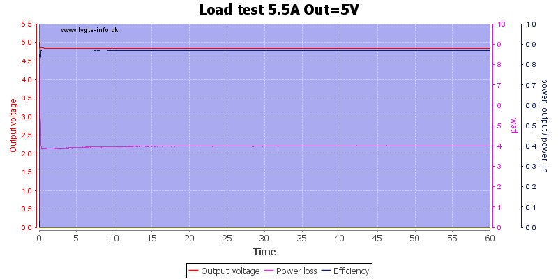
A load test with 12V input and 5V output at 5.5A, this means about 4 watt power loss in the converter.
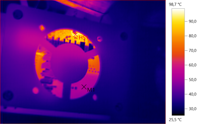
M1: 53.0°C, HS1: 98.7°C
About 100°C, this is rather warm.
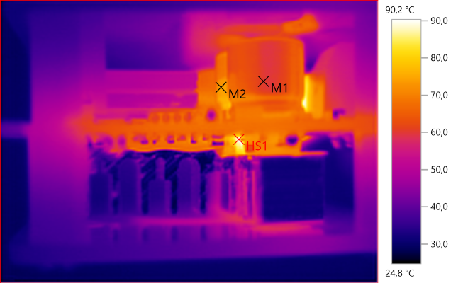
M1: 60.3°C, M2: 73.8°C, HS1: 90.2°C
The aluminium heatsink looks cool, but they are not, they are just bad at radiating heat.
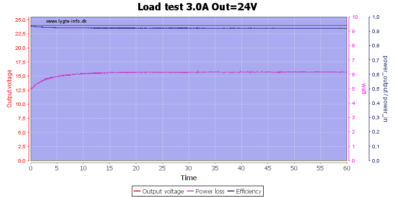
A load test with 50V input and 24V output at 3A, this means about 6 watt power loss in the converter. The display did change color with this heat.
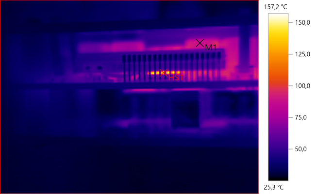
M1: 87.5°C, HS1: 157.2°C
At 160°C something is way to hot and it looks like it is the inductor.

M1: 97.7°C, M2: 103.4°C, HS1: 151.3°C
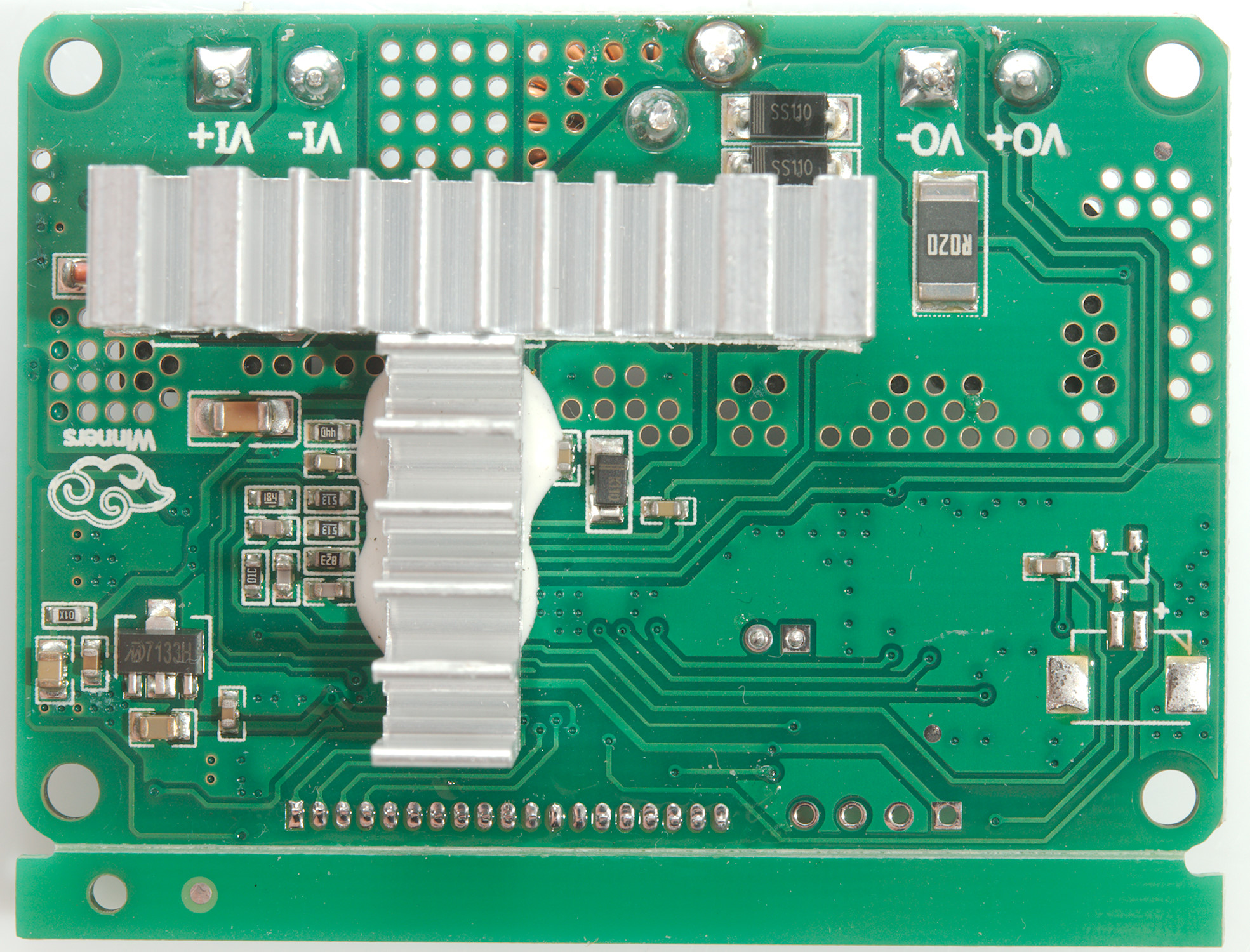
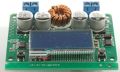
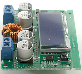
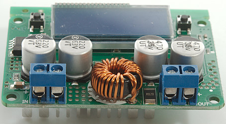
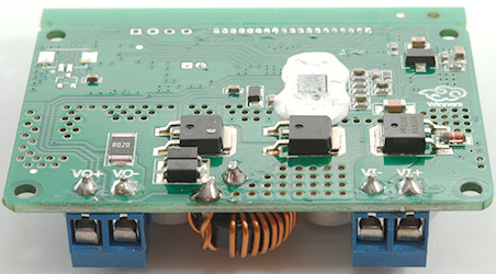
A closer look at the circuit

It was easy to remove the two covering sheets.
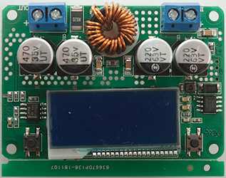
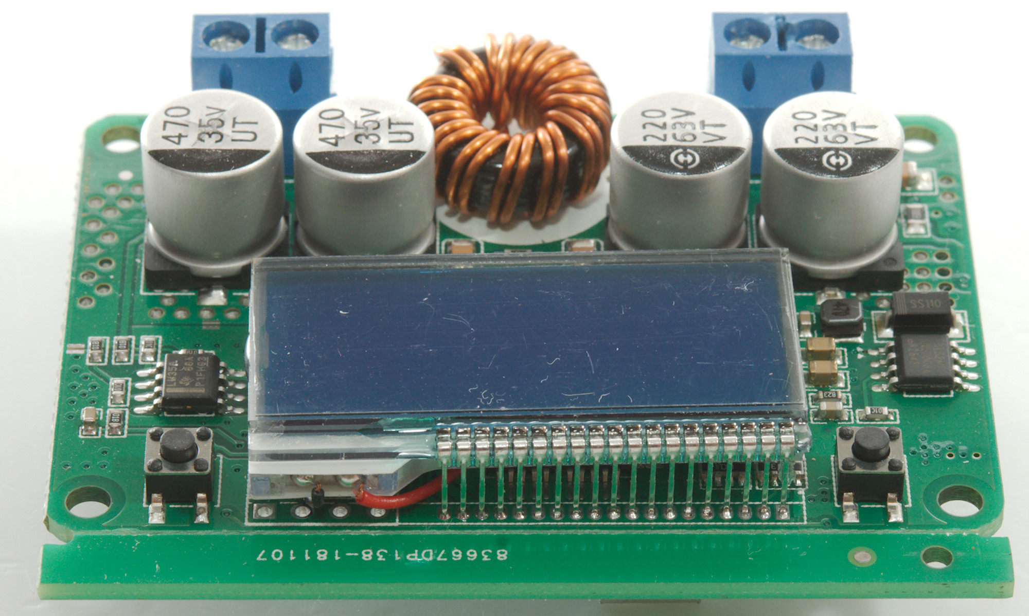
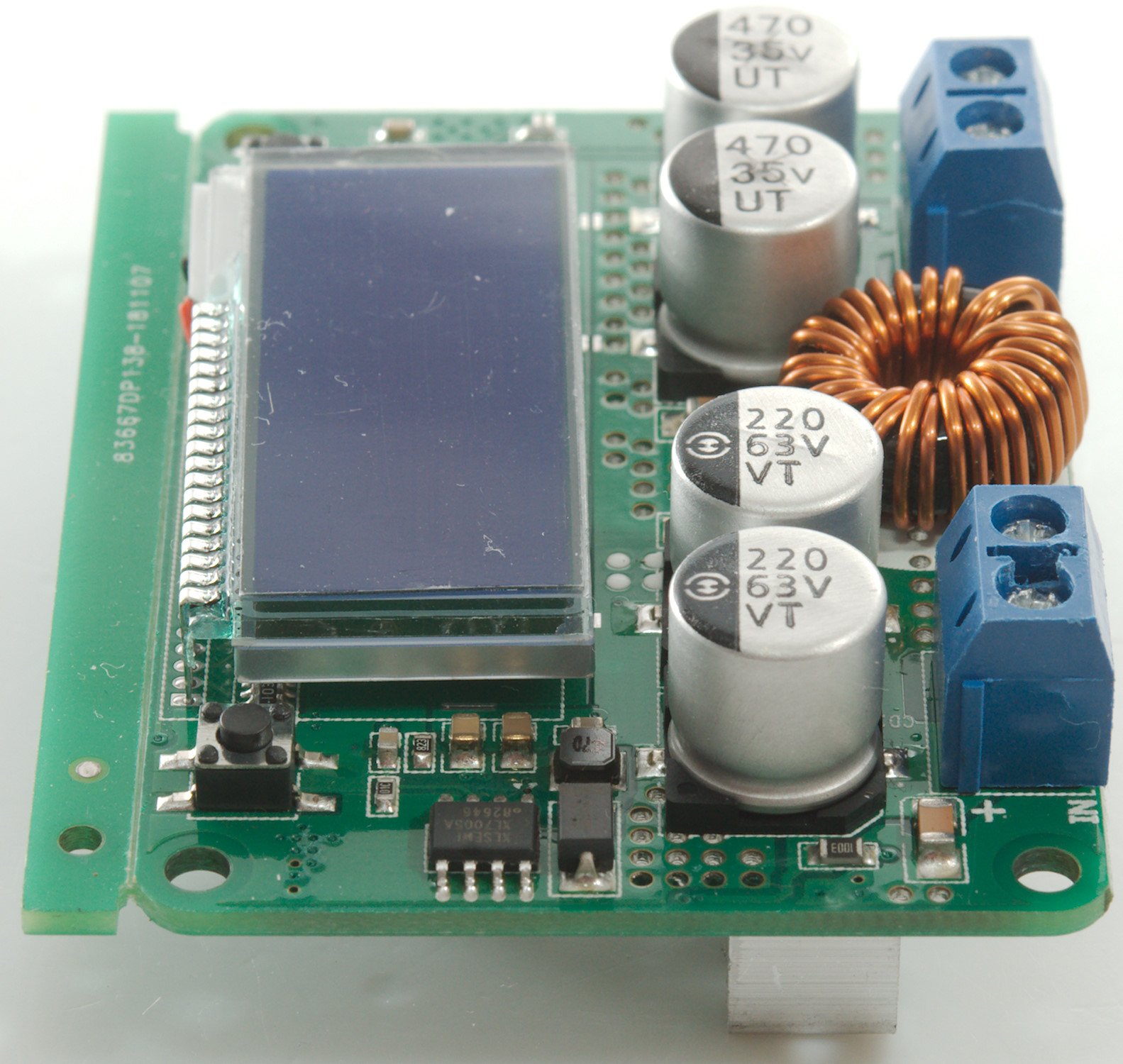
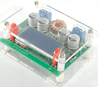
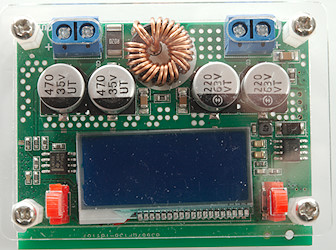
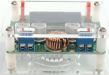
This side has the input and output terminals, the capacitors, the large and very hot inductor. There is also a small switcher (XL7005A 0.4A) withs own small inductor and diode for local power supply.
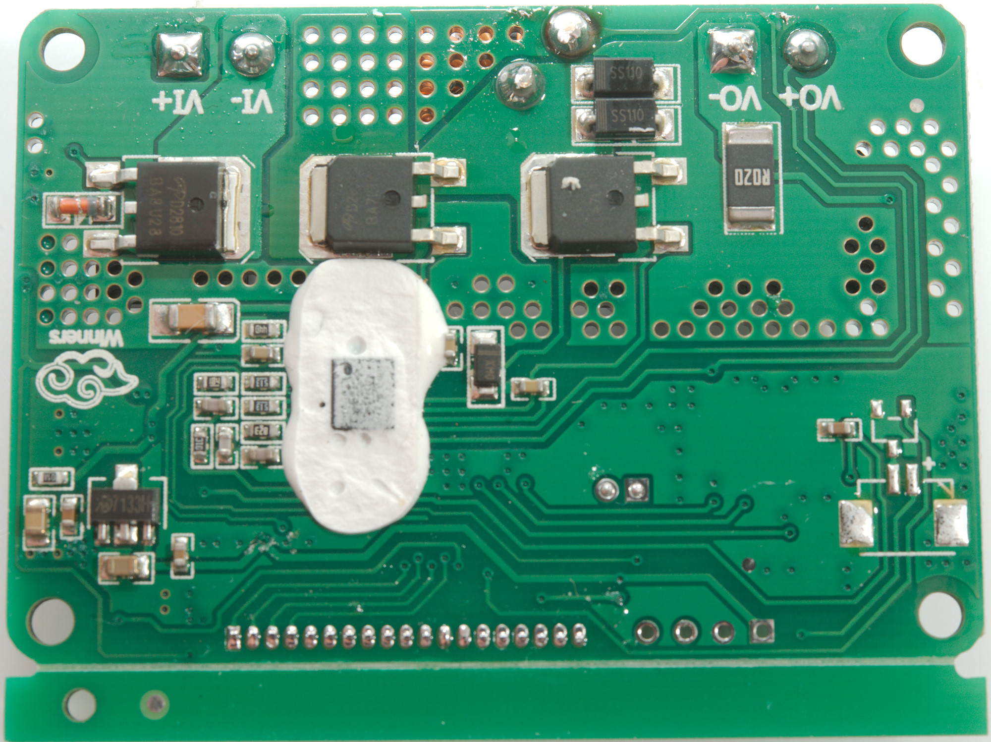
For measuring current a 0.02ohm resistor is used, this resistor is on the other side and a OpAmp (LM358) to amplify the signal. The 0.02ohm resistor on this side is for the switcher on the other side.
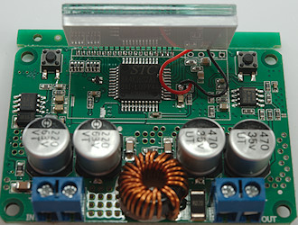
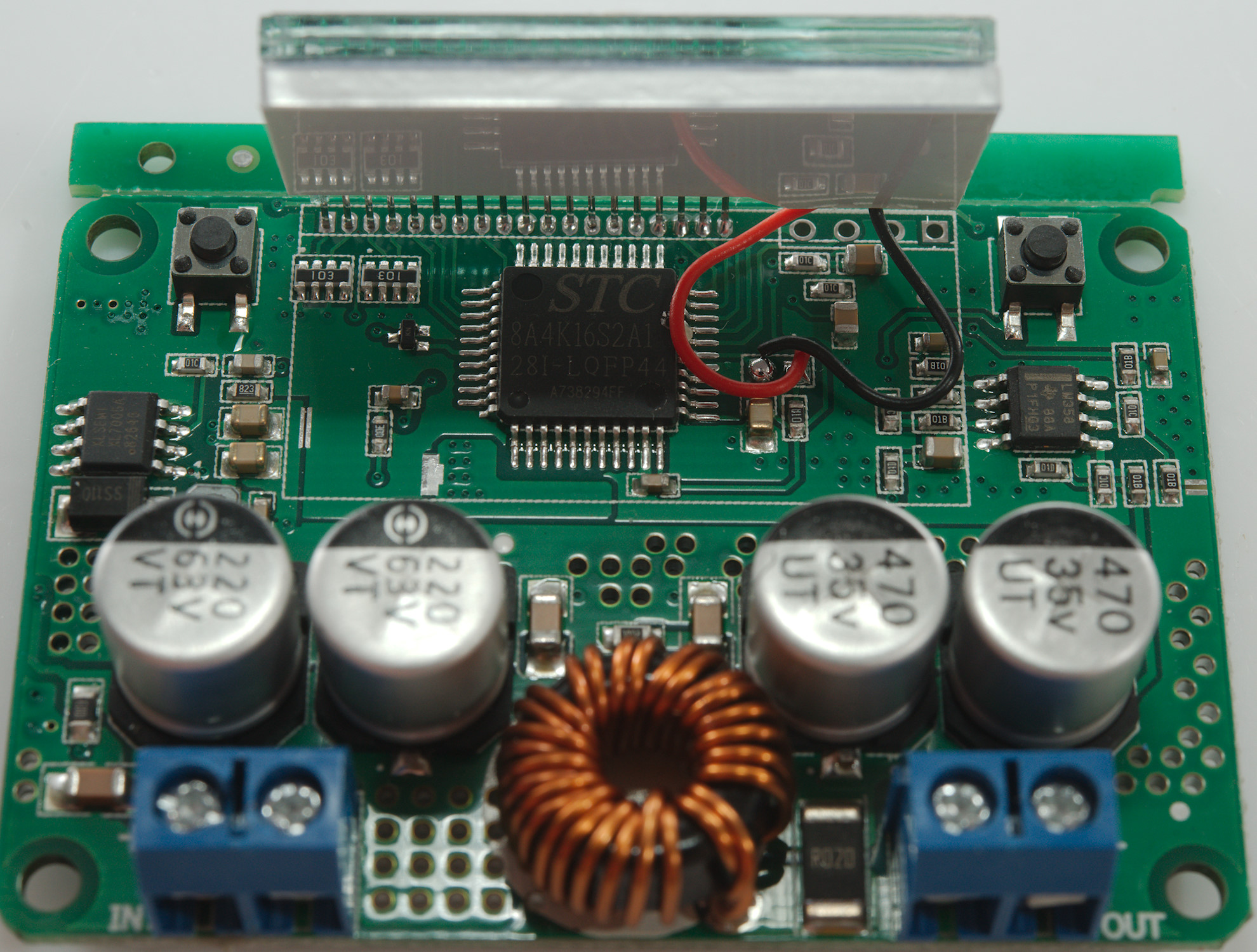
The microprocessor (STC8A4K64S2A12: 64K flash, 4K ram 8051 based) is hidden below the display. This version do not have EEPROM, this means is probably uses the flash to remember voltage setting. The controlling DAC must be with PWM and some filters, this may explain the slow setting rate when releasing the buttons.


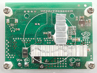
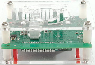
On the bottom are two heatsinks and a 3.3V regulator (7133). This regulator can only handle up to 24V input, this means a preregulator is needed, this is the small switcher on the other side of the circuit board.

Removing the heatsink shows 3 transistors and one switcher controller (LT3800: 60V input, 36V output). Two of the transistors are used by the switcher, the last is input polarity protection (Nice detail).
Conclusion
This DC-DC converter works fairly well, but be a bit vary about the specifications and do not use it directly with low voltage chips, it can be used as preregulator, but place a LDO regulator after this switcher to get rid of the noise and spikes.
For stuff running at 12V or higher the noise and spikes is not very significant and it works fine, but check my curves for current output and power loss. A 4 watt loss heats it significantly.
Notes
The converter was supplied by a reader for review.
Index to other tests