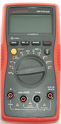
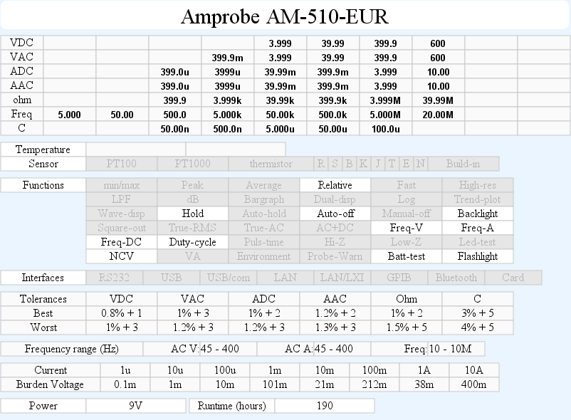
DMM Amprobe AM-510-EUR
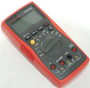
This DMM has all the normal functions and a few extra.

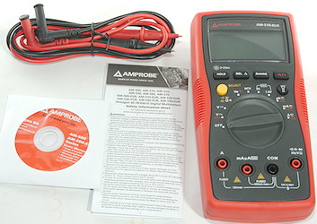
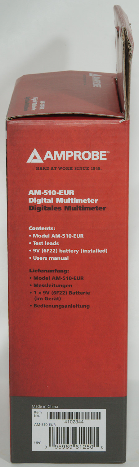
It included the DMM, a pair of probes, a safety information sheet and a mini CD with the manual (It can also be downloaded).
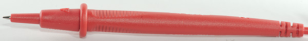
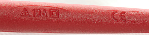
Probes are branded with Amprobe and rated for 10A
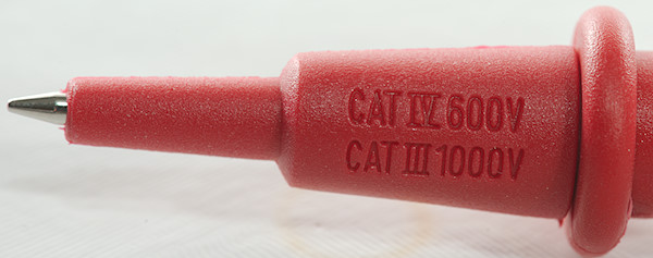
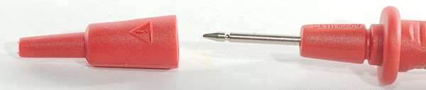
The probes has removable tip covers with CAT ratings (The DMM do not have as high CAT rating as the probes).
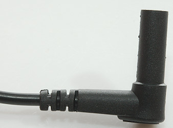
The plug is fully shrouded.
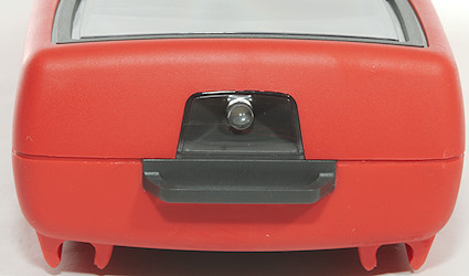
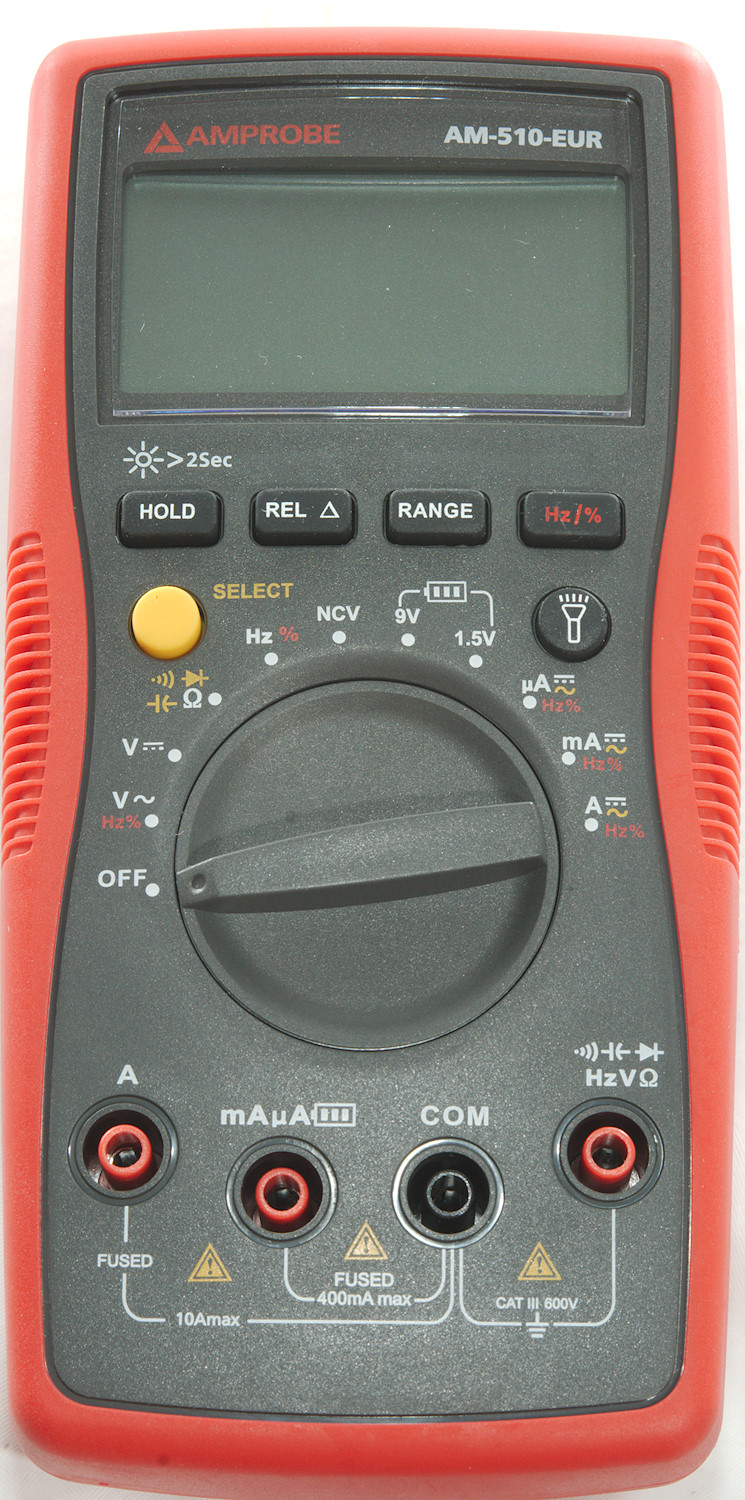
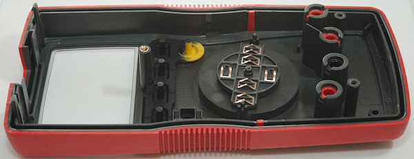
The meter has a led at the front for flashlight usage, it is behind a plastic window.
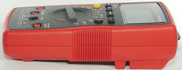
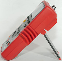
The tilting bale works very well, it is easy to extended and the rubber secures the meter do not slide around when pushing buttons or turning the range switch.
Display
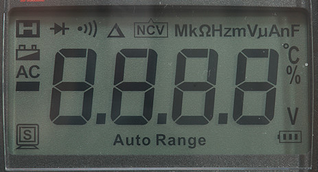
The above picture shows all the segments on the display.
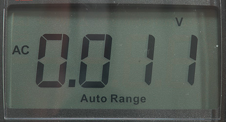
Typical display during usage, it will show the number and what measurement is selected.
Functions
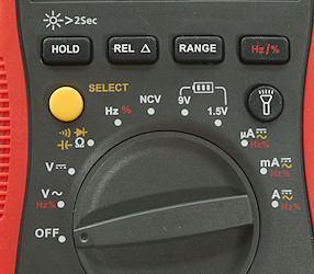
Buttons:
- Hold: Freezes the display, hold down for backlight.
- Rel: Shows values relative to current value, will also select manual range. Press again to disable.
- Range: Will disable auto range and change range, hold down to activate auto range.
- Hz % (red): Shows frequency and duty cycle in AC ranges.
- Select (Yellow): Select the ranges printed with yellow
 : Turn the flashlight on or off.
Rotary switch:
- Off: Meter is turned off
- VAC: Show AC voltage, using the red button frequency and duty cycle can be selected.
- VDC: Show DC voltage.
- ohm...: Resistance, continuity, diode and capacitance.
- Hz: Frequency and duty cycle.
- NCV: Non contact voltage, i.e. detect electric fields.
- 9V: Test 9V battery, note probe must be connected to mA input.
- 1.5V: Test 1.5V battery, note probe must be connected to mA input.
- uA: Current AC and DC. In AC the red button will show frequency and duty cycle.
- mA: Current AC and DC. In AC the red button will show frequency and duty cycle. Watch out for burden voltage.
- A: Current AC and DC. In AC the red button will show frequency and duty cycle.
Input
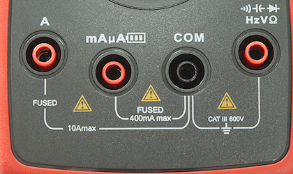
- A: High current, maximum current is 10A
- mAuA: The lower current ranges, also used for testing batteries.
- CON: The common terminal for all ranges.
- xxx: All other ranges.
Measurements
- Volt and frequency
- Frequency counter and duty cycle can only be selected in AC ranges.
- Frequency input do not require a zero crossing.
- Frequency input requires about 0.2V before it works.
- At 1Vrms frequency input range is from 0.5Hz to 20MHz
- Duty cycle works from 2% to above 99% at 100kHz with 1Vpp, precision is within 0.3
- 1 VAC is 5% down at 2kHz.
- If there is a large DC voltage on the AC, it will show 0 in AC
- Input impedance is 10-11Mohm on DC, AC and mVAC
- There is only mV range in AC and it must be manually selected.
- Frequency input resistance is 2Mohm at 1V, then increases to 10Mohm up to 12V, it then drops to 3kOhm at 30V
- Rated overload protection is 600VDC on DC range and 600VAC on AC range
- Current
- Frequency counter and duty cycle can only be selected in AC ranges.
- uAmA input is protected by a 0.5A/660V 6.3x32mm fuse
- A input is protected by a 10A/660V 6.3x25mm fuse
- Ohm, continuity, diode and capacitance
- Ohm needs about 3.5s to measure 100ohm
- Ohm is 0.42V open and 0.16mA shorted
- Continuity is normal (About 70ms).
- Continuity beeps when resistance is below 40ohm and is noisy up to about 90ohm.
- Continuity is 0.44V open and 0.16mA shorted
- Diode range uses 1.5V, max. display is 0.999V at 0.16mA, max. current is 0.51mA shorted
- In the lower capacitance ranges REL must be used (Offset is about 13nF on my meter)
- 100uF takes about 16 seconds to measure.
- Rated overload protection is 600VAC
- Miscellaneous
- Battery test for 9V uses 1Kohm load resistor
- Battery test for 1.5V uses 30ohm load resistor
- Rated battery overload protection is the 0.5/600V fuse.
- Current consumption of meter is 2.2mA to 3mA (9mA with backlight, 26mA with backlight and flashlight)
- Meter works down to 5.4V where display starts to fade and will turn off at around 5V, battery symbol show at 6.4V.
- Reading will change slightly with battery voltage: 3 count on a 10V reading from 9V to 6V.
- Backlight varies with battery voltage and goes off at around 5.4V
- Flashlight works down to about 2.7V on battery.
- The meter usual need a couple of display update to reach the final value and may show a too high value for a moment.
- Viewing angle is good
- Display updates around 3 times/sec
- Backlight will automatic turn off in about 15 seconds.
- Will automatic turn power off in about 30 minutes.
- Standard probes fits fine.
- Generally the precision is not "spot on", but within the specified tolerances.
- Weight is 360g without accessories, but with batteries.
- Size is 190 x 91 x 50mm.
- Probes
- Probe resistance 24mOhm for one (Black probe had a loose connection).
- Probe wire is soft and 87cm long.
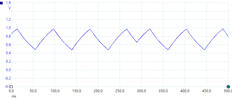
A look at the capacitance measurement waveform.
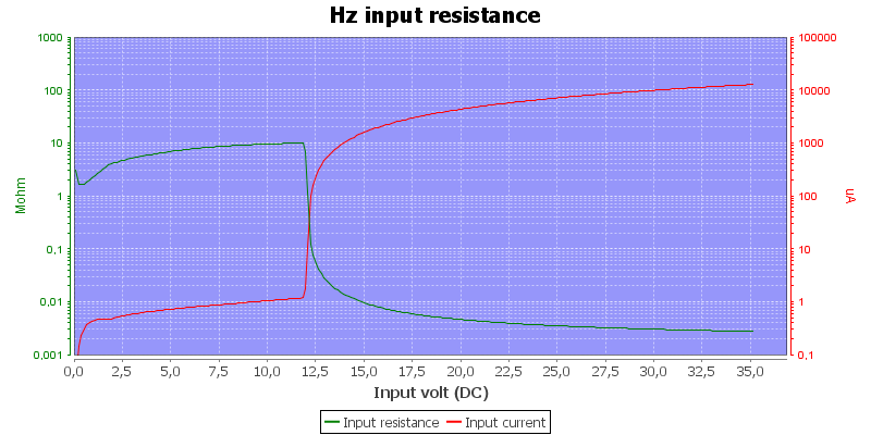
Frequency input resistance.
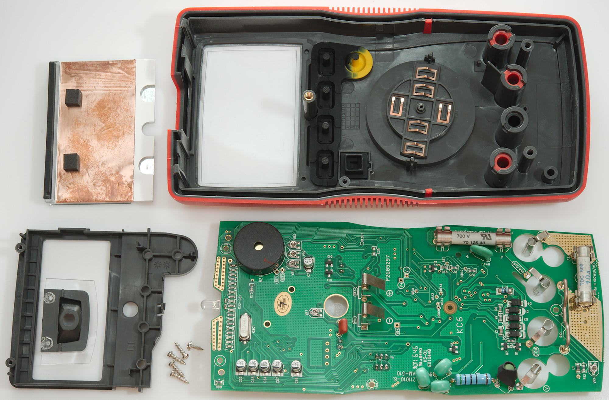
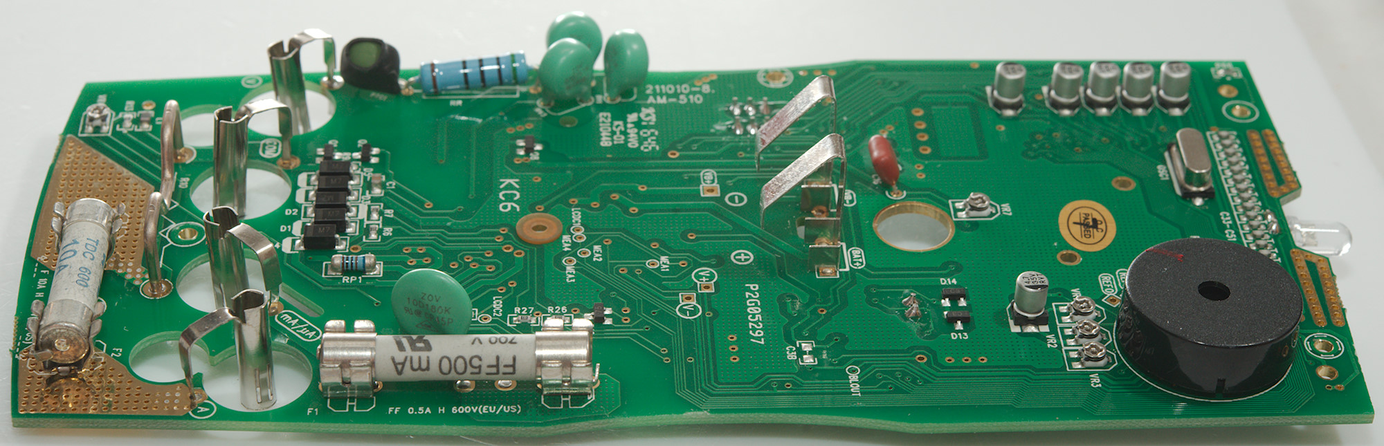
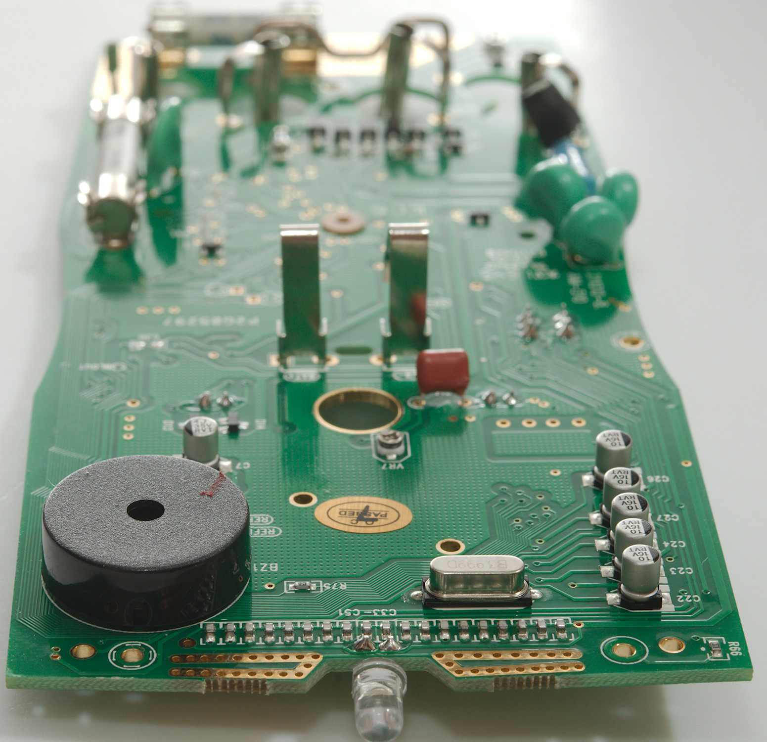
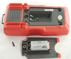
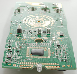
Tear down
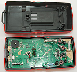
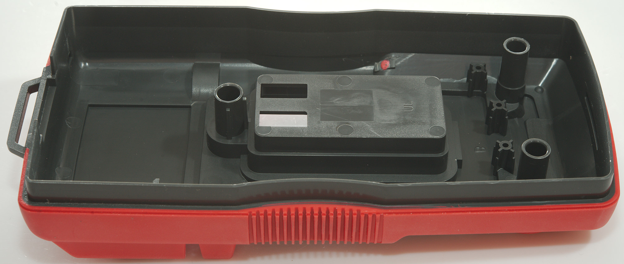
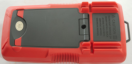
3 screws (One was for the battery cover) and the back could be removed.
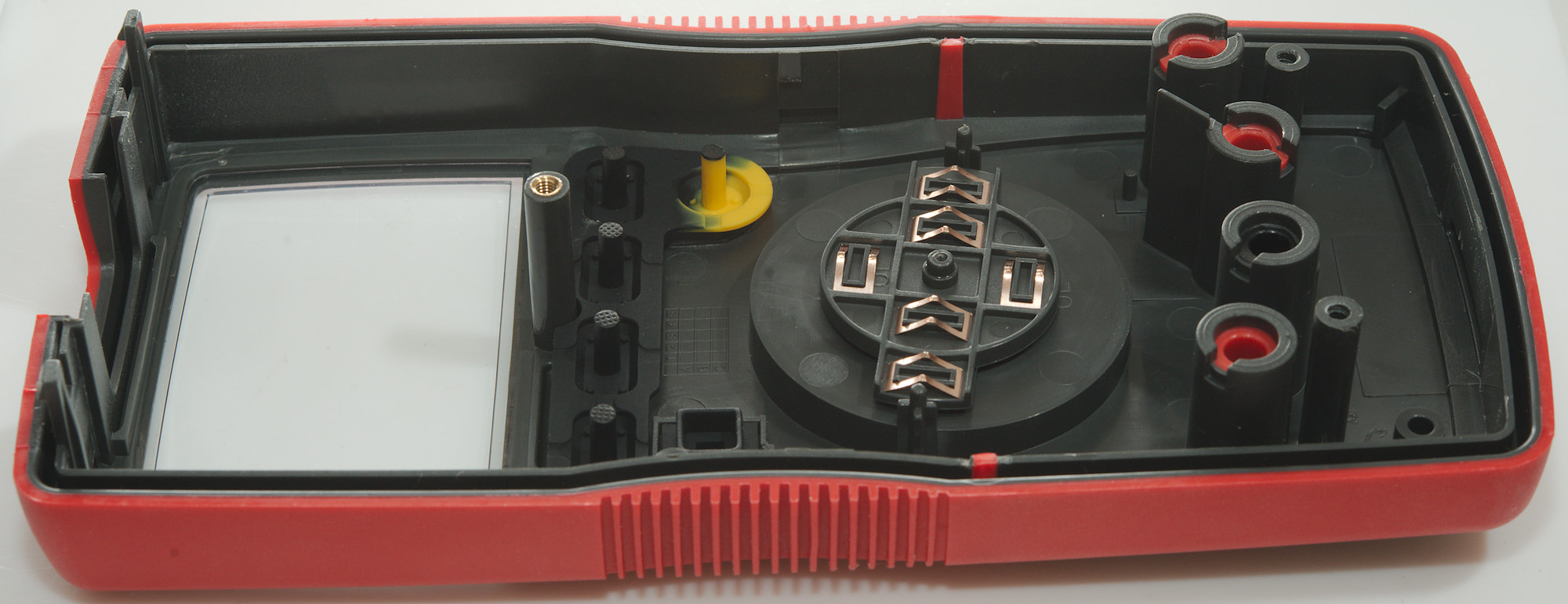
3 more screws for the circuit board and two for the lcd cover.
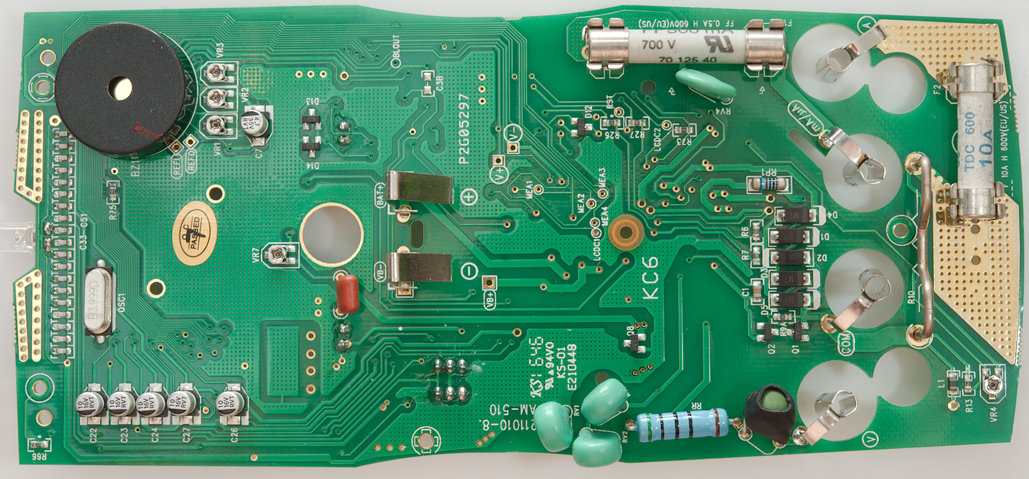
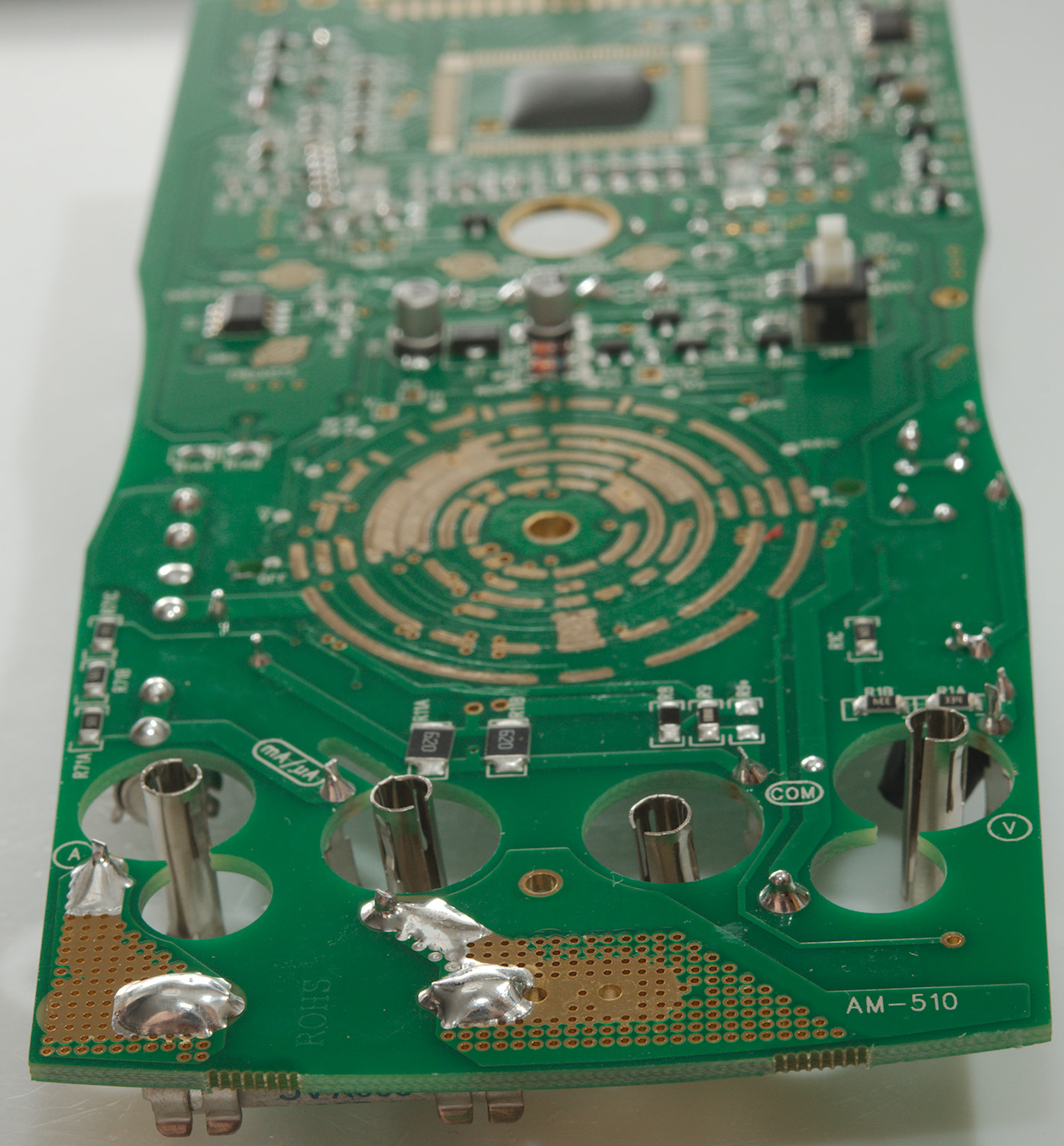
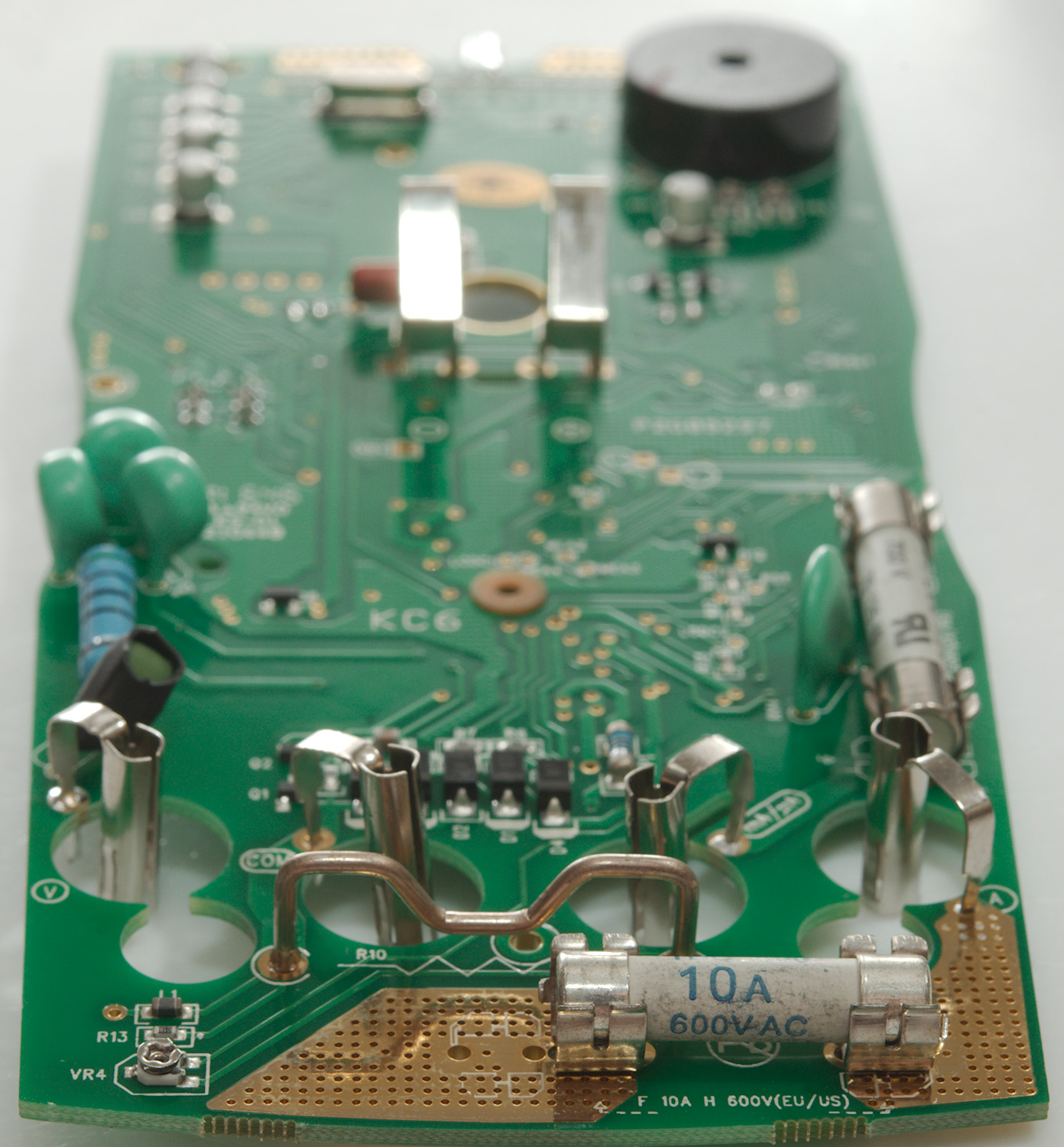
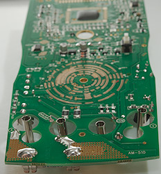
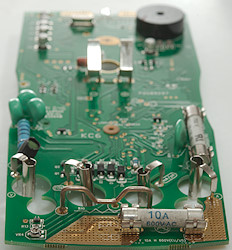
Notice the isolation wing on one of the current input terminals, with a blown fuse they must withstand a lot of voltage.

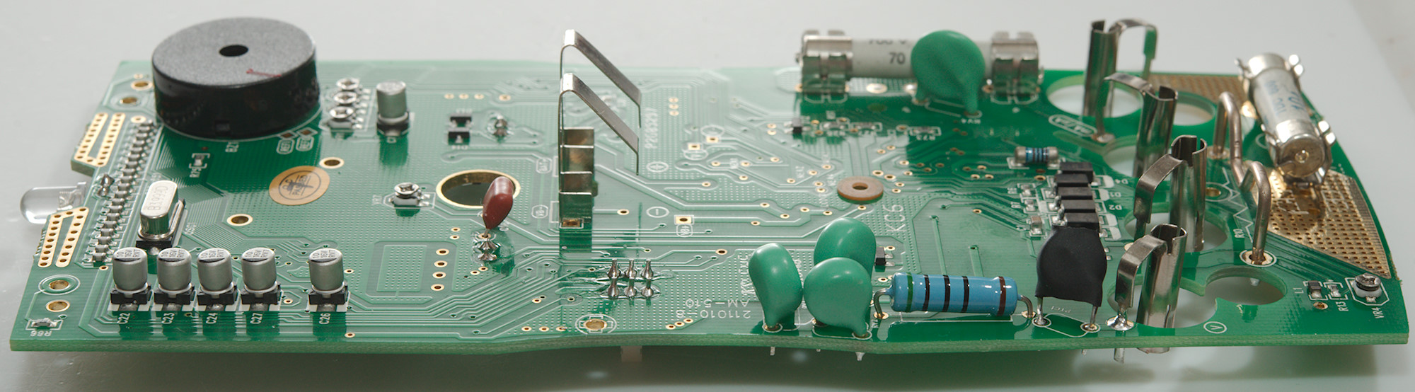
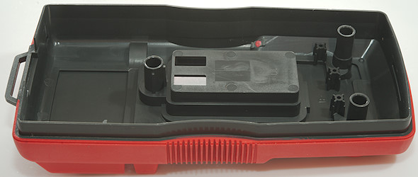
The circuit board is shaped to fit exactly in the case with indents that that match the case.
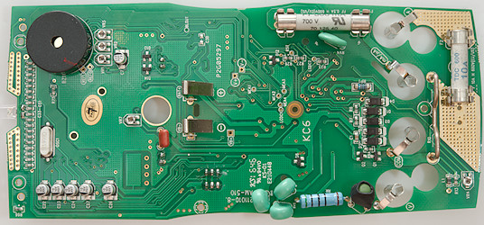
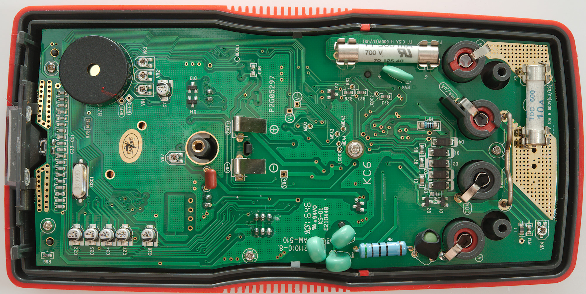
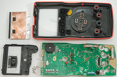
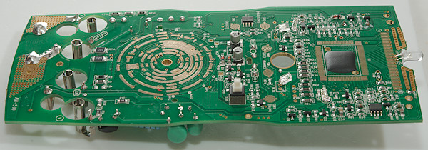
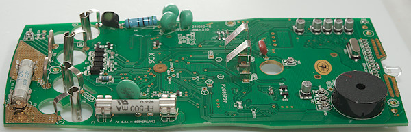
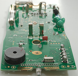
There is two ceramic fuses, one for mA/uA (F1:500mA) and one for A (F2:10A), the diodes above the input terminals is for protecting the mA and uA current shunts against over current. There is also a MOV near the mA/uA fuse (RV4: 10D180k, 18V full clamp at 36V), it will clamp voltage in battery test mode. The resistor besides the diodes (RP1: 1kOhm) is probably for the 9V testing.
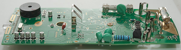
At the volt terminal is a PTC followed by a 500ohm resistor (One of the MOV's is connected before the resistor), this is probably used for ohms/capacitor current output, but also for voltage input. At the top of the circuit board is the led for the flashlight and the antenna for the NCV detector.
Q1, Q2 and D13, D14 is probably input protection for different ranges.
There is also a couple of trimpots (VR1..VR4, VR7) on the circuit board, these are probably the reason for the calibration is not spot one (It can be hard to adjust trimpots precisely).
One interesting detail is the fuses, the circuit board can be mounted with holders for both long and short fuses, in this meter the mA fuse is long and the A fuse is long, I wonder why.
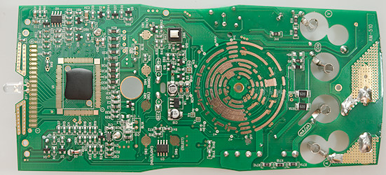
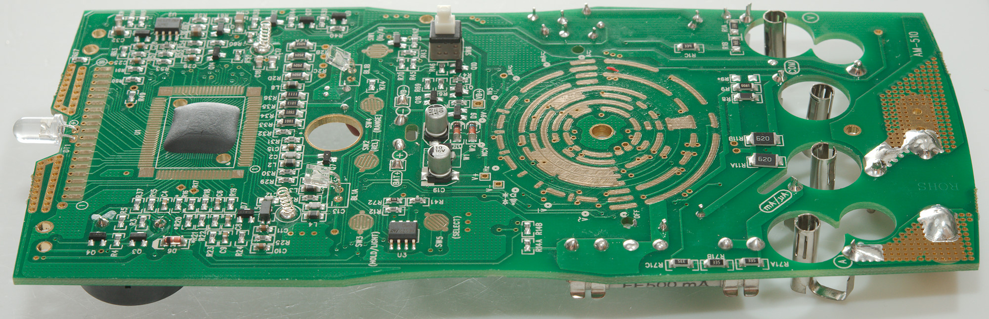
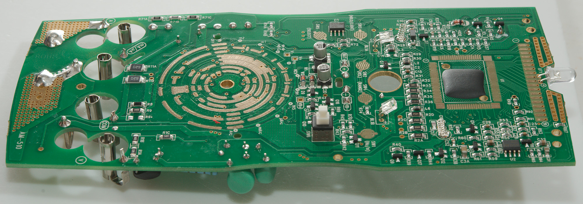
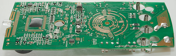
Near the mA/uA & COM inputs we have the current sense resistors for uA (R8: 99ohm), uA (R9: 1ohm) and 1.5V battery test (R11A & R11B 2x62ohm in parallel). Near the current terminal a input voltage divider (R71A, R71B, R71C: 3x3.3M in series), it is connected to the mA/uA input terminal and is probably used for battery testing.
There is also a 10MOhm input near IC1 (R2A, R2B, R2C, R2D: 4x2.5MOhm), it is feed from after the 500ohm resistor (RR)
The main voltmeter chip (U1) is a COP, making it impossible to see the number.
There is two (Probably) OpAmp (U2 & U3: GZ534).
The switch for the flashlight is a regular switch (SW6).
Conclusion
This meter has all the usual functions and a some extra like flashlight, battery test and NCV. As usual the burden voltage in the high mA is rather high, the meter is missing mVDC and capacitance measurements only goes to 100uF
The meter has a lot of protection and the fuses are rated for 600V.
This meter looks like it is fine for mains voltage and anything below.
Notes
How do I review a DMM
More DMM reviews