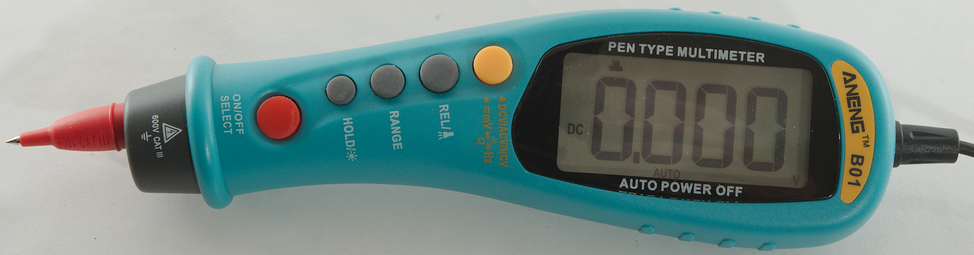
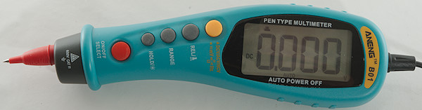
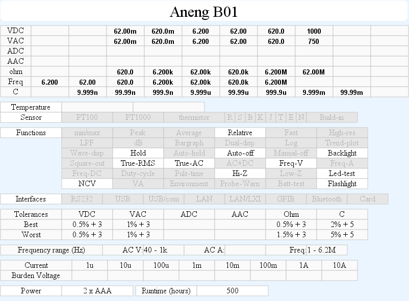
DMM Aneng B01
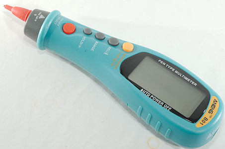
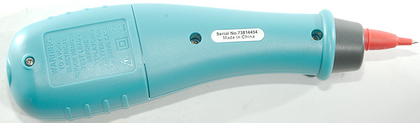
This is a pen type multimeter, i.e. one probe is part of the multimeter.
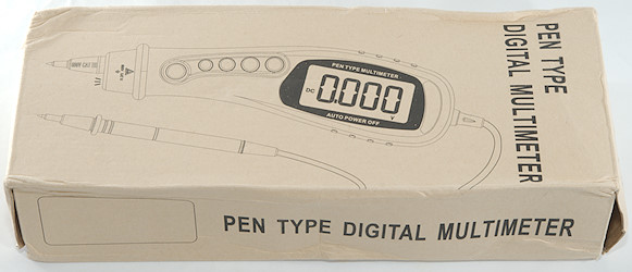
I got it in a cardboard box without any interesting information on the outside.
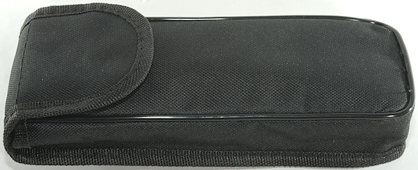
The box contained the meter bag with everything inside the bag.
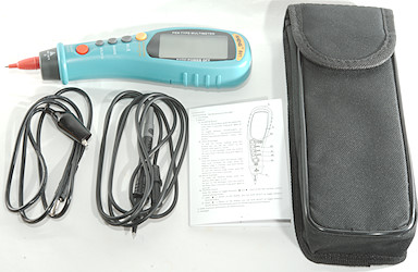
It included the DMM, a black probe, a black alligator clip wire, an instruction sheet and a bag.
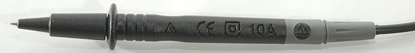
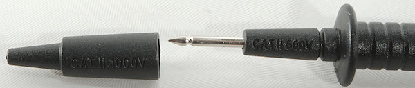
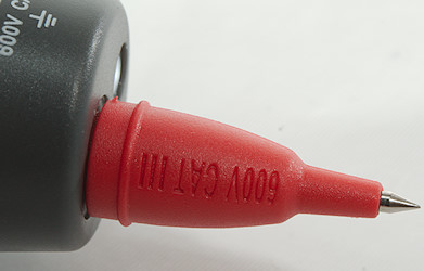
The probes has removable tip cover, but with or without the cover it is only rated for CAT II either 1000V or 600V.
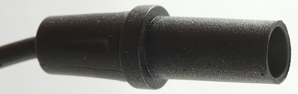
The plug is fully shrouded, but shorter than standard probes.
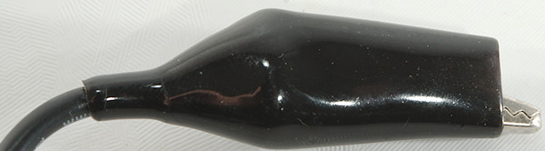
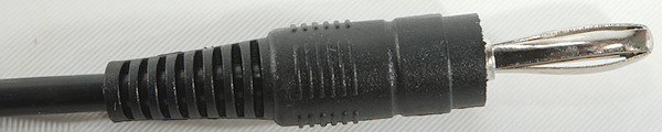
The wire with alligator clip uses a standard banana plug.
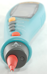
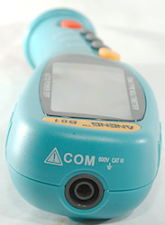
The front of the meter is the red probe, there is also a flashlight. On the back of the meter is the socket for the black probe.
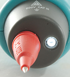
Here the flashlight is on.
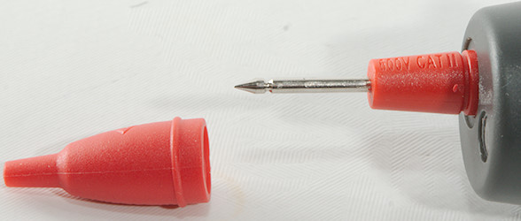
The tip cover can be removed, rating is the same as for the loose probe.
Display
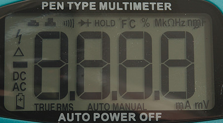
The above picture shows all the segments on the display, not all are used by the mter.
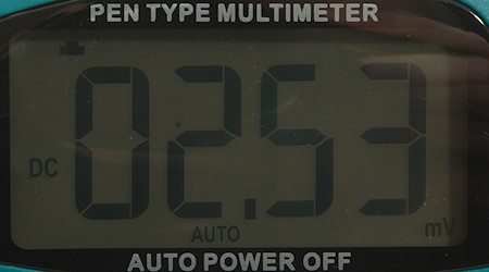
Typical display during usage, it will show the number and what measurement is selected. When selecting range It requires checking the top and bottom of the display to see what is selected.
Functions
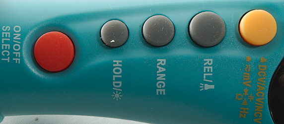
Buttons:
- (Yellow) up position: DCV, ACV, Frequency, NCV
- (Yellow) down position: DCmV, ACmV, Ohm, Continuity, Diode, Capacitance, Frequency
- Rel: Shows values relative to current value, will also select manual range. Press again to disable. Hold down to turn flashlight on.
- Range: Will disable auto range and change range, hold down to activate auto range.
- Hold: Freezes the display, hold down for backlight.
- On/off select: Changes between the modes listed for the yellow button, hold down to turn on/off. Using the yellow button will always reset to the start of the modes listed
Input
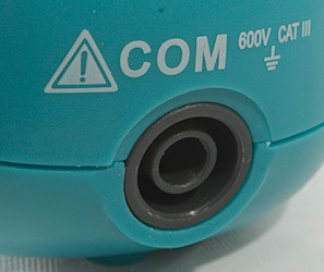
One probe is part of the multimeter, the other is connected at the back.
Measurements
- Volt and frequency
- At 100mVrms frequency input range is from 1Hz to 5.6MHz
- At 1Vrms frequency input range can be stretched to 6.2MHz where it shows OL
- 1 VAC is 5% down at 2kHz (RMS will not work at the frequency).
- Frequency counter requires a zero crossing.
- NCV will flash background light in addition to sounding the buzzer.
- Input impedance is 10-11Mohm on DC and AC
- mV range is high impedance for DC and 10Mohm for AC, but impedance drops to 2kohm above 2V.
- Frequency input is 10Mohm, but impedance drops to 2kohm above 2V.
- Current
- Ohm, Continuity, diode and capacitance
- Ohm needs about 2.6s to measure 100ohm
- Ohm is 1.0V open and 0.39mA shorted
- Continuity is fast (Below 20ms).
- Continuity beeps when resistance is below 50ohm.
- Continuity is 1.0V open and 0.39mA shorted
- Diode range uses 3.2V, max. display is 3.0V at 0.13mA, max. current is 1.7mA shorted
- 70000uF takes about 10 seconds to measure.
- 10uF takes about 4 seconds to measure.
- These ranges are specified to not handling any voltage input.
- Miscellaneous
- Current consumption of meter is 1.5 to 1.9mA, flashlight adds 11mA, backlight adds 24mA (Total is 36mA with backlight and flashlight)
- Meter works down to 2.0V where it turns off, battery symbol show at 2.4V.
- Reading is stable with changing battery voltage.
- Backlight only works down to about 2.6V where it is fairly dim.
- The meter usual need a couple of display update to reach the final value.
- Viewing angle is good, except from the top.
- Display updates around 3 times/sec
- Backlight will automatic turn off in about 120 seconds.
- Flashlight will turn off together with the meter and do not have any shorter timeout.
- Will automatic turn power off in about 15 minutes.
- Standard probes cannot be pushed fully down.
- Weight is 136g without accessories, but with batteries.
- Size is 201 x 53 x 35mm.
- Probes
- Probe resistance 120mOhm.
- Probe wire is soft and 148cm long.
- Lead with alligator clip is 84cm long.
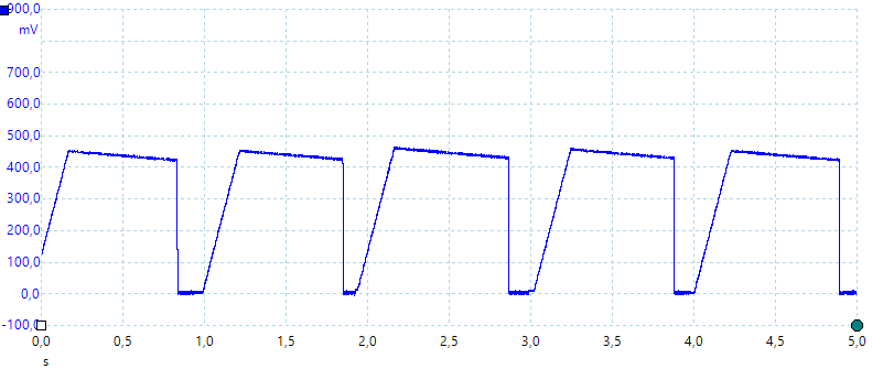
A look at the capacitance measurement waveform.
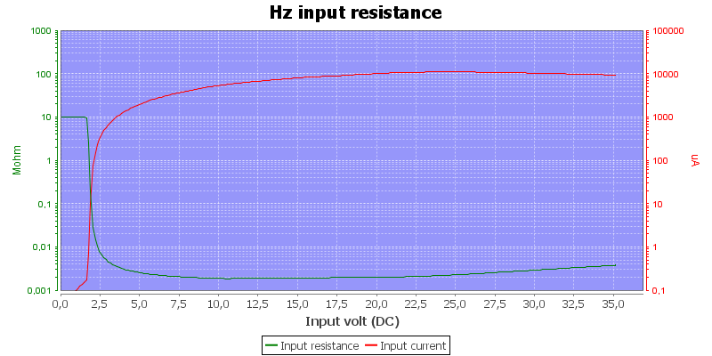
Frequency input resistance.
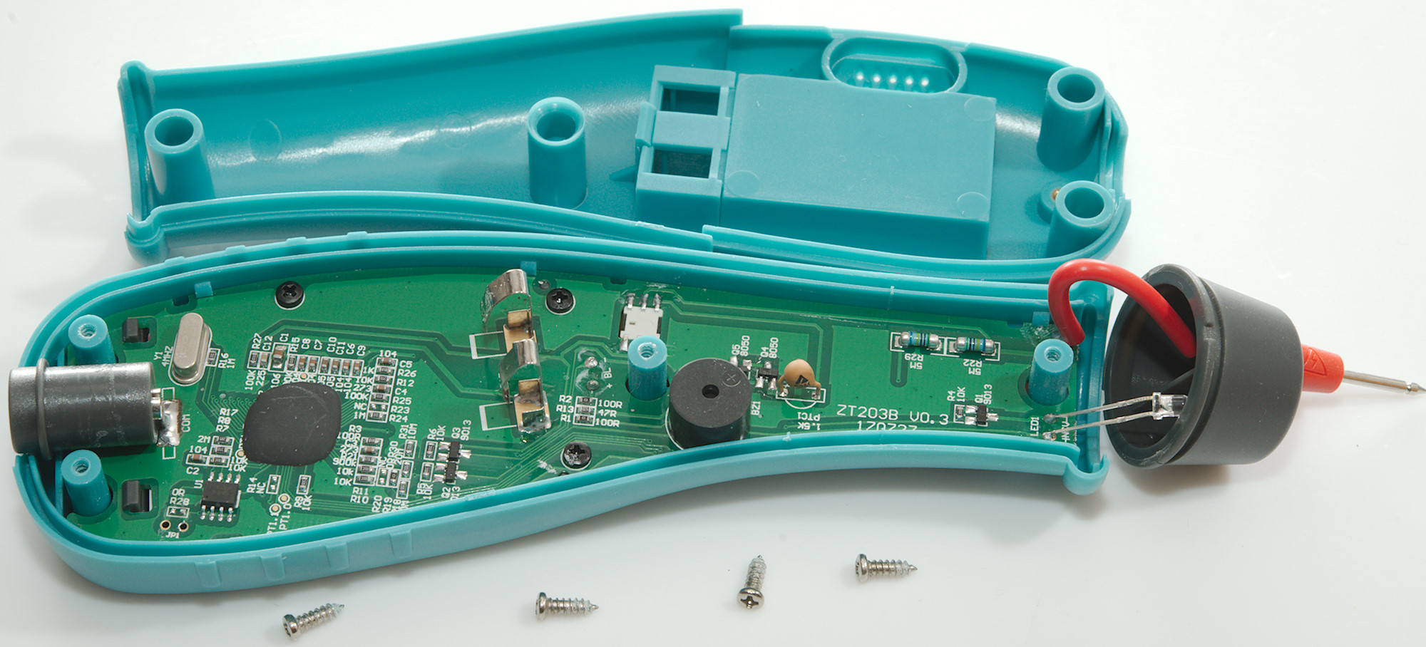
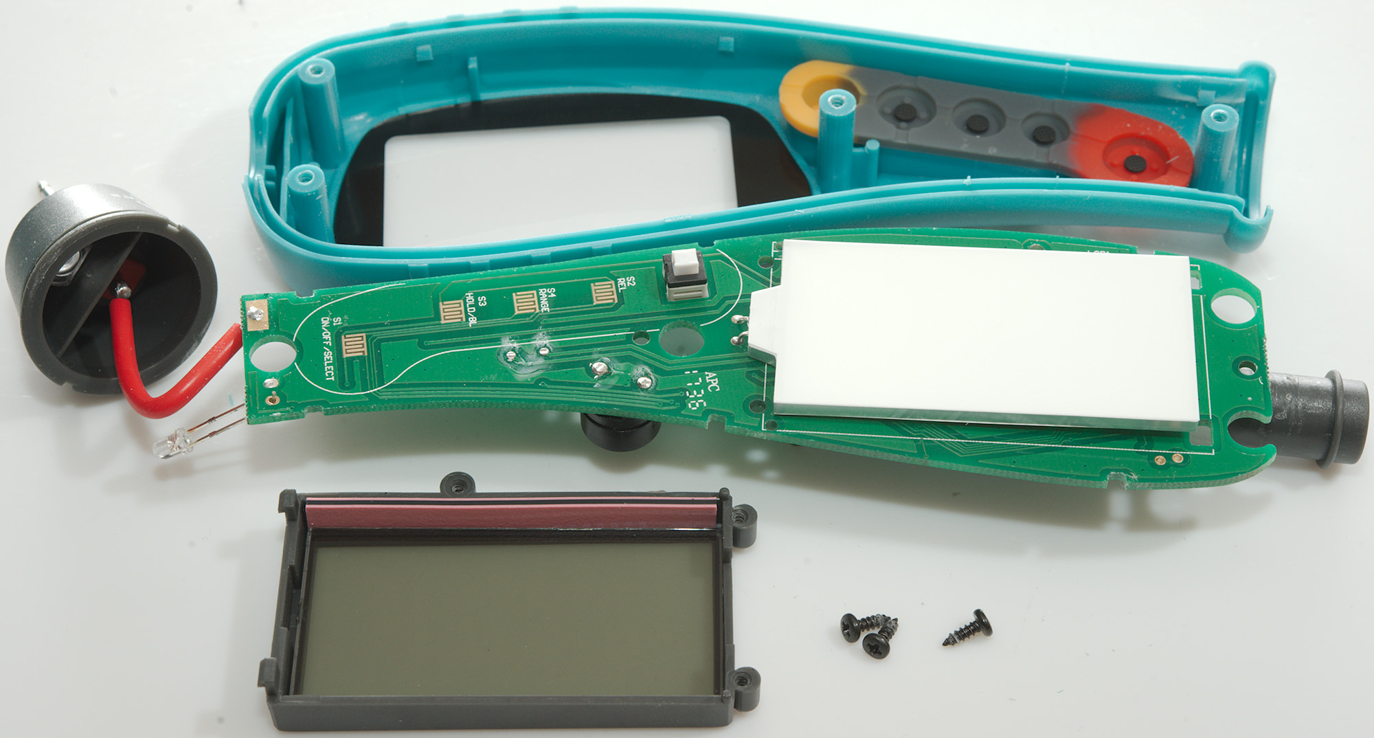
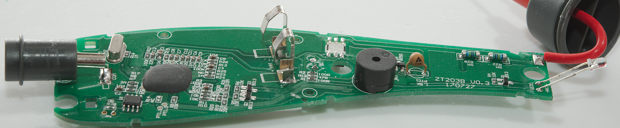
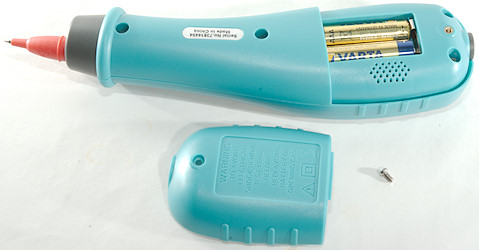
Tear down
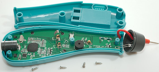
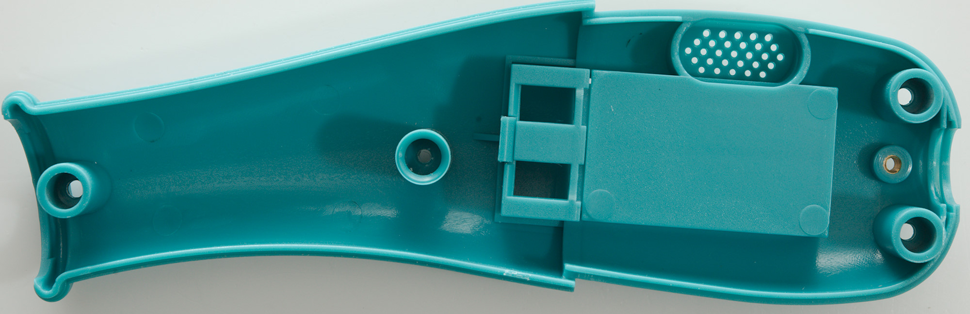
Four screws and the back could be removed.
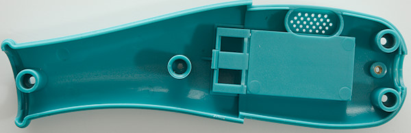
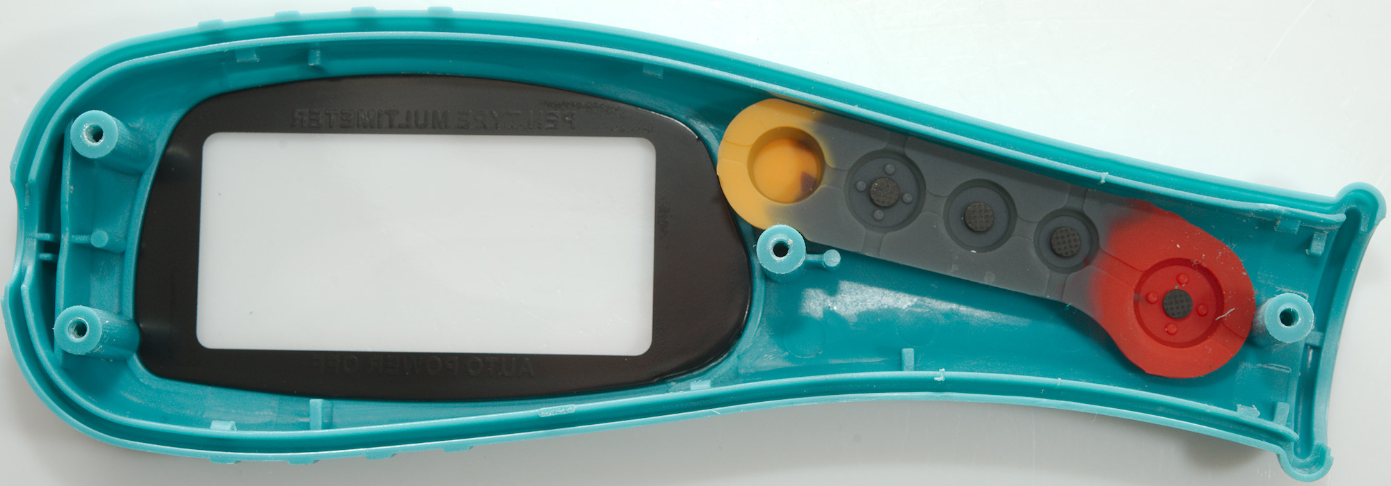
The back has holes for the sound from the buzzer, but the holes end below the battery cover? (The buzzer is load enough).
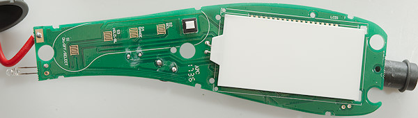
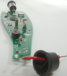
The circuit board is mounted with clips, the 3 screws are for the display. I wonder how long the yellow (white here) switch is going to last. A hard press on it may pop the soldering and nothing else is holding it.

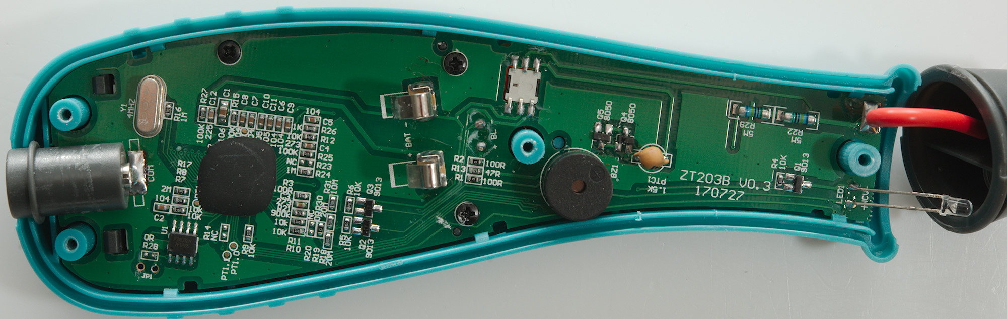
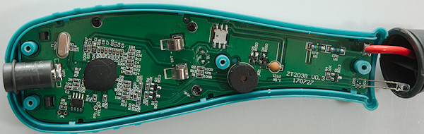
Display and circuit board removed.

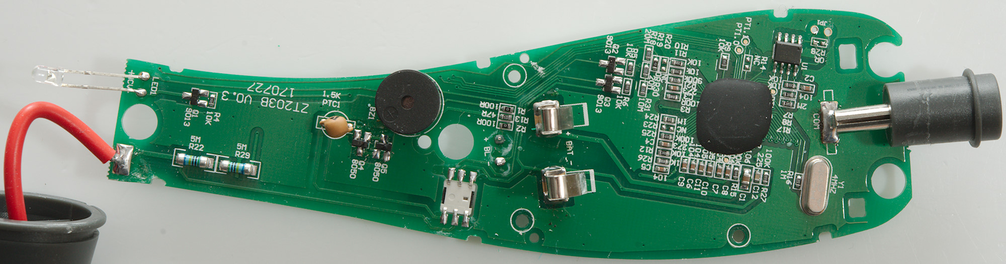
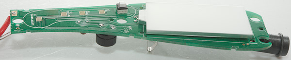
The yellow button has a real switch behind it.
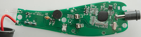
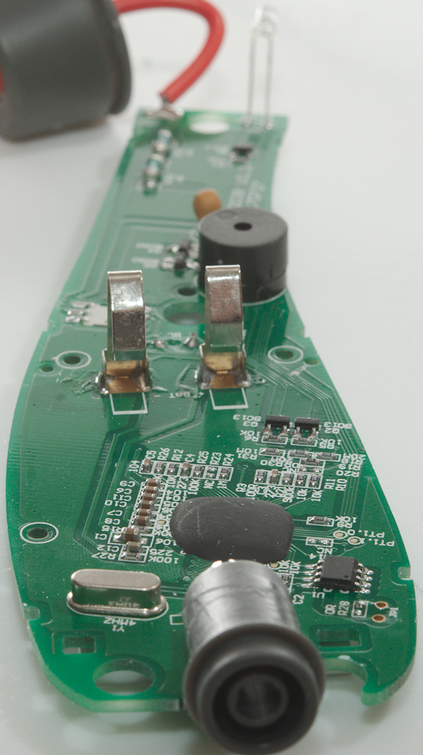
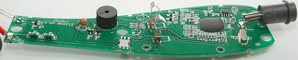
The input resistors (R22, R29: 2x5Mohm) are permanently attached to the input terminal. The input terminal is also connected to the switch and can be routed to a PTC (PTC1: 1.5kOhm) and a transistor clamp (Q4, Q5). Interesting enough a wire also goes from the input side of the PTC further up the circuit board. I traced it to another input resistor (R21: 900kOhm). This do not look like a area or resistor that can handle high voltage!
Near the multimeter chips is a EEPROM (U1: P24C02A) for calibration and functions.
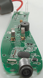
There is no risk of the led getting close to the input, there is a wall between.

Conclusion
As usual I doubt the CAT rating, the meter must handle 600V in all ranges, but the manual says not to put voltage into the ohms ranges.
The meter works fine and has many functions including a flashlight and NCV, but finding the correct measurement can be a bit frustrating with all the pushes on the yellow and red buttons. There is also a complete lack of any current measurements.
I like the large digits on the display, but the units showing what is selected, is a bit small.
Notes
This meter may exist with many different names on it and small variations in functions.
How do I review a DMM
More DMM reviews