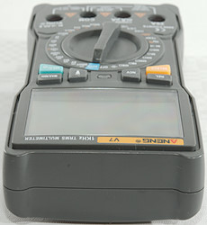
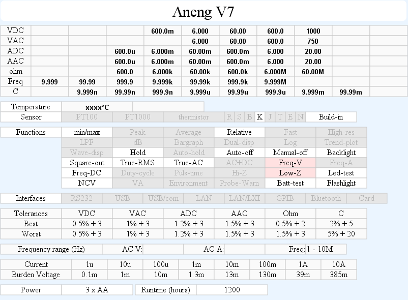
DMM Aneng V7
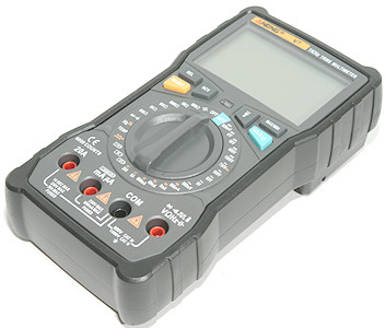
This is a cheap DMM with all common function. It is both manual and auto ranging.
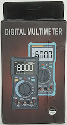
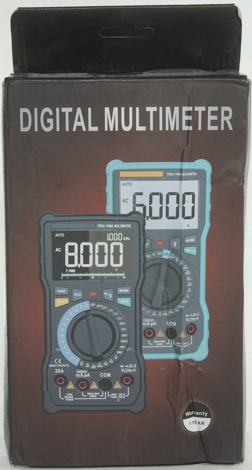
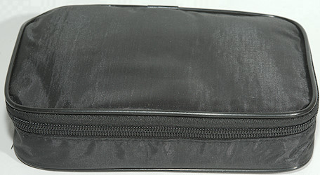
The box for the meter is designed for both the V7 and V8 meter.
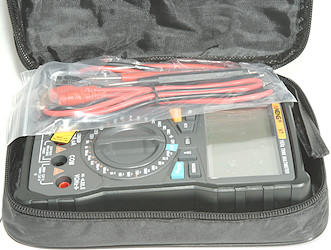
Inside the box is a pouch with everything in it, except the manual.
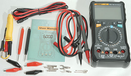
The package included the DMM, a pair of standard probes, the universal probes, a thermocoupler and a manual in addition to the pouch.
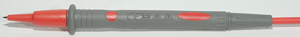
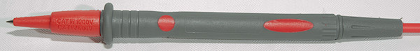
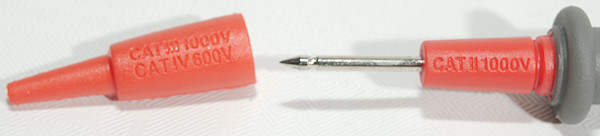
The probes are unbranded and has removable tip covers and is rated for CAT II 1000V and CAT IV 600V
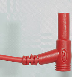
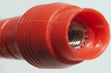
The plug is shrouded.
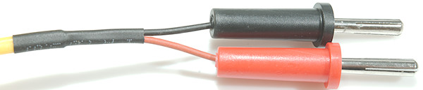

The thermocoupler is designed for insertion into stuff and is with banana plugs.
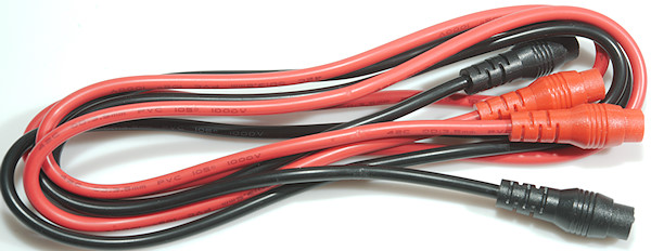
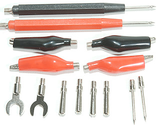
The universal probes can be assembled to many different configuration, they are not high quality, but very useful.
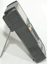
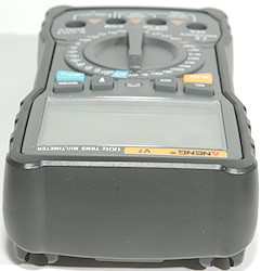
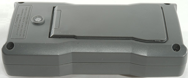
When using the tilting bale it is possible to turn the switch, but not use the buttons with one hand.
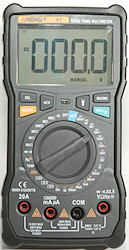
Display
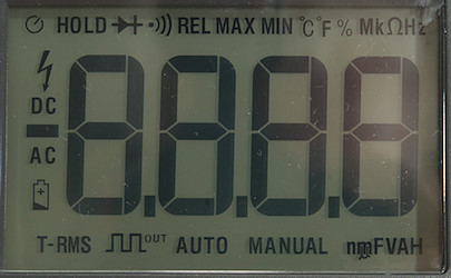
All the segments on the display.
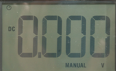
Typical screen during usage, show the range.
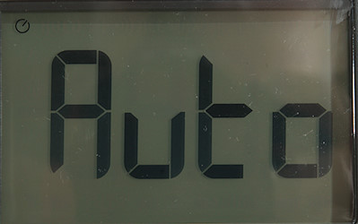
In auto mode it will show "Auto" until voltage or resistance is detected.
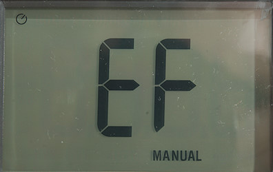
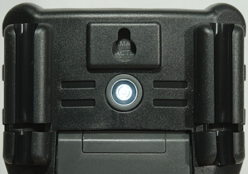
Holding down the NCV button will show EF (Electric field) on the display and change to bars when a actual field is detected. The led below the display will flash red and the buzzer will also sound.
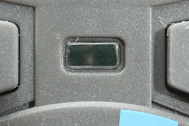
Between the buttons is a led, it can show red, green and "yellow", it is used for NCV, continuity and battery test.
Functions
Buttons:
- Rel: Shows values relative to current value, will also select manual range. Press again to disable.
- NCV: When held down the meter is in NCV mode, will override any selected range.
- Select (Yellow): Select the ranges printed with yellow (Hz/duty-cycle, DC/AC, frequency in 750VAC, frequency for frequency out) mode and between °C/°F
 : Turns the flashlight on.
- Max/min: Starts recording maximum and minimum value, press to select between max/min, hold down to disable
- Hold (Blue): Freezes the display reading, hold down for backlight to turn on.
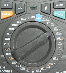
Rotary switch:
- Off: Meter is turned off
- Auto: Meter is in automatic mode, it can measure volt and resistance and will automatic select range.
- 5 x VDC: The different volt DC ranges from 600mV to 1000V.
- 5 x VAC: The different volt AC ranges from 600mV to 750V.
- 6 x A: The different current ranges, use SELECT to change between AC and DC.
 : 12V Battery test
 : 9V Battery test
 : 1.5V Battery test
 : Frequency output from 50Hz to 5000Hz, use SELECT to step the frequency.
- Temp: Temperature with a thermocoupler, use SELECT for °C/°F
- Hz %: Frequency and duty-cycle.
 : Continuity and diode mode, there is no selection, it is a single mode that do both and for a combined mode it works fairly well.
- 6 x ohm: The manual resistance ranges, the 600ohm range is only present here, AUTO will not use it.
 : Capacity
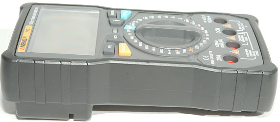
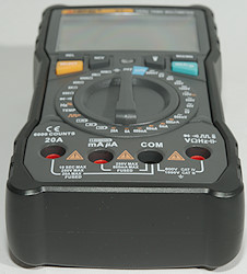
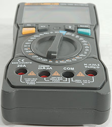
Input
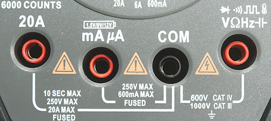
- 20A: High current, it can only withstand 10+ ampere for a short time (Fuse is 10A).
- mAuA: The lower current ranges, the selector switch will change between two different shunts (Fuse is 600mA).
- CON: The common terminal for all ranges.
- xxx: All other ranges.
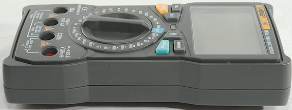
The terminals fairly retracted into the meter.
Measurements
- Volt and frequency
- At 1Vrms input frequency input range is from 0.7Hz to 5MHz
- Frequency input can handle a DC offset from -2.2V to 2.2V with 1Vrms input.
- Duty cycle works from 1% to above 90% at 100kHz with 2Vpp, precision is within 2.0
- Duty cycle works from 1% to above 99% at 100kHz with 4Vpp, precision is within 0.1
- 1 VAC is 5% down at 2.1kHz (RMS will not work at the frequency), AUTO and manual is similar.
- Max/min needs less than 150ms to capture a voltage, but need many pulses for it.
- Input impedance is between 0.8 and 0.9Mohm on DC and AC
- Input impedance is 10Mohm in mV ranges, up to about 2V, then it drops to 2kOhm.
- AUTO needs about 0.85V DC or 0.8V AC to select range, it beeps when below 50ohm, lowest ohm range is 6kOhm.
- In AUTO mode the input voltage must be below 500V, above it will show OL and beep.
- Current
- 20A range will give audible alarm at 10A and show OL above 20A
- Overload protection in uA and mA: 0.6A/250V 5x20mm ceramic fuse
- Overload protection in A: 20A/250V 6x30mm ceramic fuse
- Ohm, Continuity, diode and capacitance
- Ohm needs about 0.6s to measure 100ohm (Manual range makes it very fast), using AUTO it is about 1.5s
- Ohm is 1.0V open and 0.27mA shorted in 600ohm range
- Ohm is 0.7V open and 1.6uA down to 0.5uA shorted in other ranges
- Continuity is fast (About 20ms), AUTO is very slow (About 500ms).
- Continuity beeps when resistance is below 50ohm, this is also when it switches from diode to continuity.
- Continuity & diode is 3.9V open and 0.27mA shorted
- Continuity & diode uses diode mode from 0.07V to 3.0V, current at 3V is 0.27mA
- 10uF takes about 4 seconds to measure.
- 11000uF takes about 11 seconds to measure.
- No overload protection is rated, except for AUTO mode.
- Miscellaneous
- 12V battery test uses a 100ohm resistor
- 9V battery test uses a 910ohm resistor
- 1.5V battery test uses a 180ohm resistor
- Frequency output has the following frequencies: 50, 100, 200, 300, 400, 500, 600, 700, 800, 900, 1000, 2000, 3000, 4000, 5000Hz
- Current consumption of meter is 1.2mA to 2.4mA, diode is 2.4mA, most ranges are around 1.6mA (Backlight add 3.2mA, flashlight 2.6mA, max total current is 8.2mA).
- Meter works down to 2.1V where it shows OL, it turns off at 2V, battery symbol show at 2.9V.
- Reading is stable down to 2.3V, then it will increase.
- Backlight and flashlight is stable down to 3.1V where it will fade out at 2.6V
- The meter usual need a couple of display update to reach the final value.
- Viewing angle is good.
- Display updates around 3 times/sec
- Flashlight do not turn automatic off, but will turn off when the meter turns off.
- Backlight will automatic turn off in about 120 seconds.
- Will automatic turn power off in about 16 minutes.
- Standard probes can nearly be pushed fully down.
- Weight is 412g without accessories, but with rubber sleeve and batteries.
- Size is 176 x 91 x 47mm with rubber sleeve.
- Probes
- Standard probe resistance 40mOhm for one.
- Standard probe wire is 79cm long.
- Custom probe resistance is 56mOhm
- Custom probe wire is 86cm long
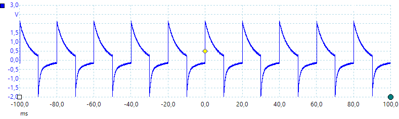
A look at the capacitance measurement waveform.
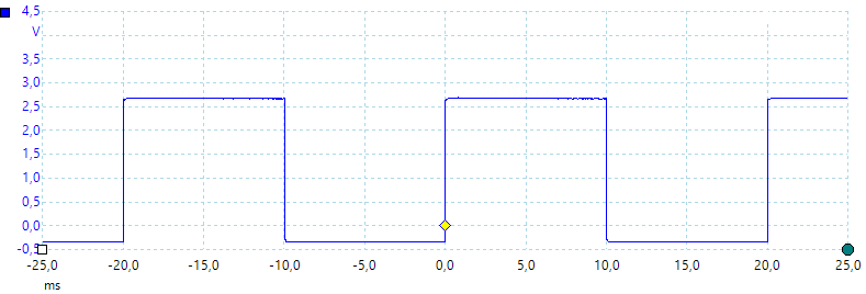
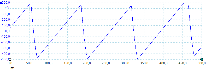
50Hz frequency output, it goes slightly below zero.
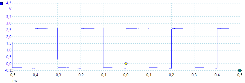
5000Hz frequency output, it also goes slightly below zero.
50Hz output loaded with 3700 ohm halved the RMS output voltage, there is a output capacitor that is on the small side.
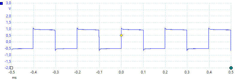
5000Hz output with 1220ohm load, again the output is halved, but the curve looks much better.
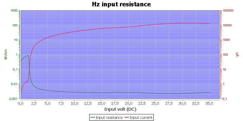
Frequency input resistance depends on input voltage.
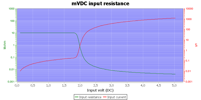
The mV range has 10Mohm, until the protection clamps, this is measured on the 600mV range, AC and DC is similar.
Voltage input is a bit low in input impedance at 1Mohm in manual range and 280kOhm in AUTO mode, this is basically always Low-Z.
It handled a mix of AC and DC voltage rather well, the AUTO shows the highest or both if they are similar.
It only supports showing frequency in 750VAC range or with the logic input frequency range.
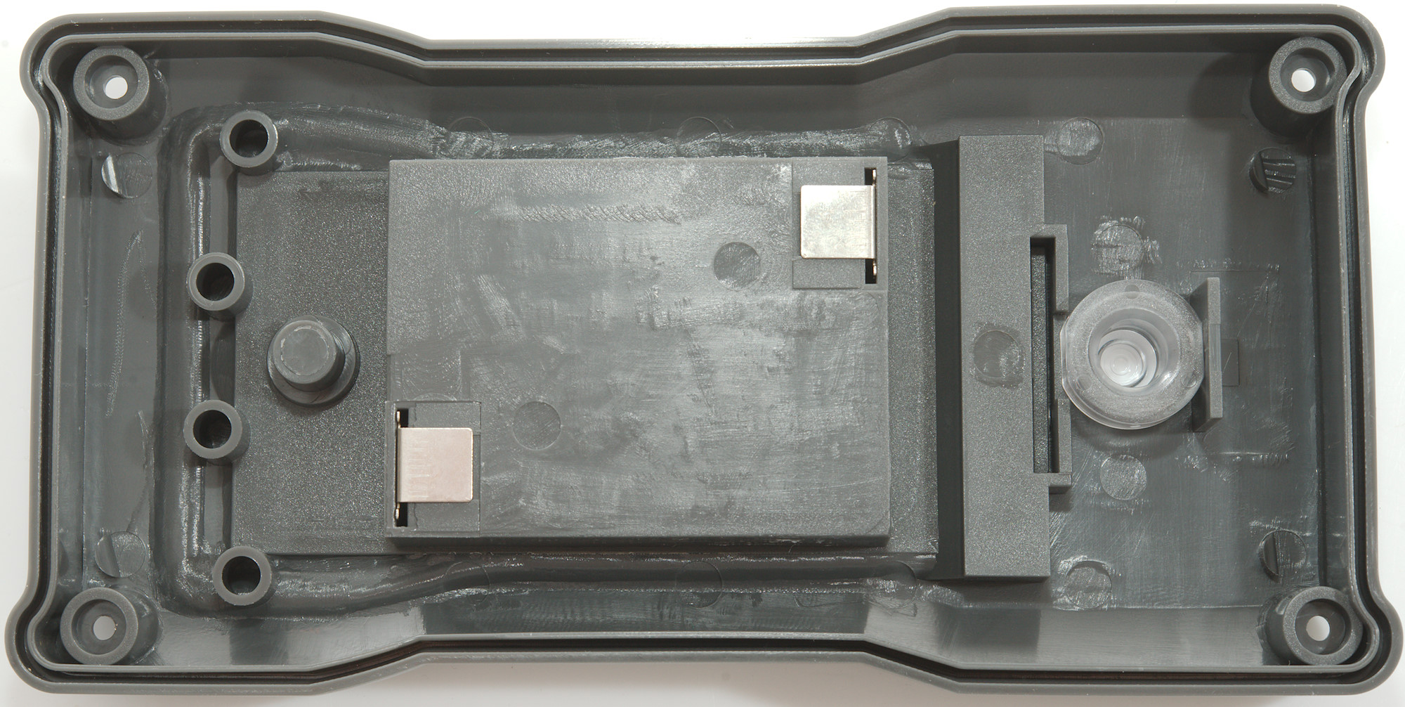
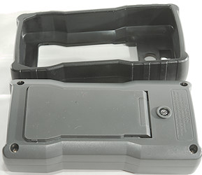
Tear down
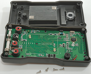
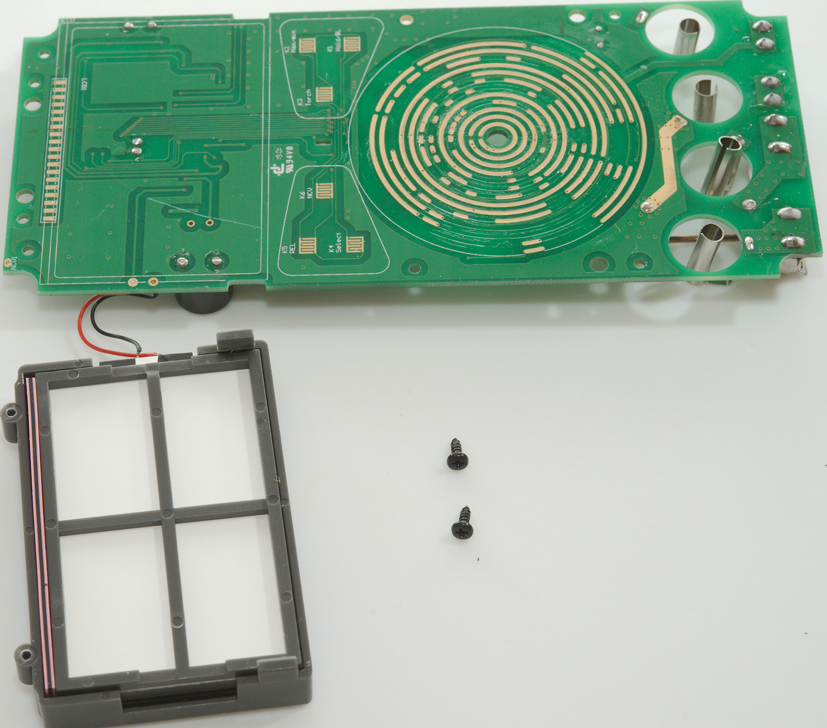
I had to remove four small screws to open the meter.
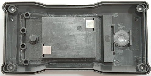
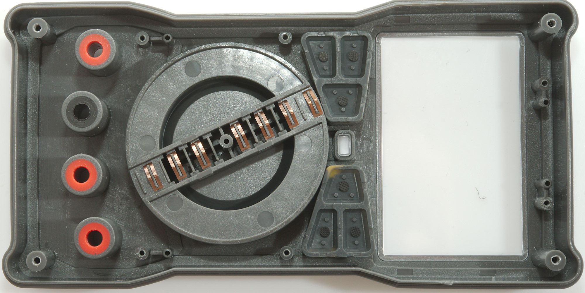
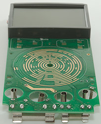
And six more screws to remove the circuit board
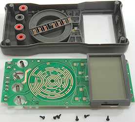
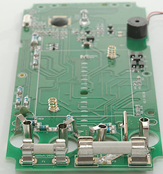
The range switch has seven contacts, a lot of encoding must be done to tell the chip what range is selected, a few signals must also be switches.

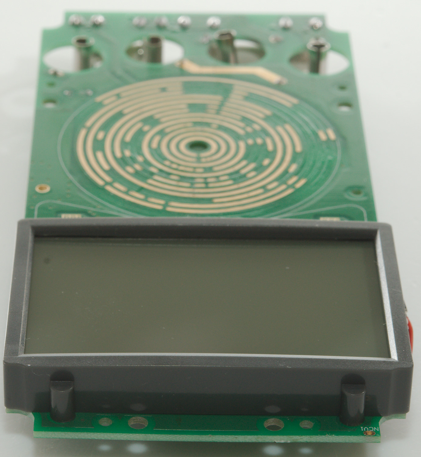
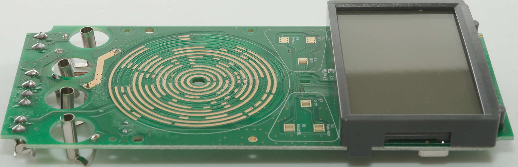
The LCD display is screwed and clipped to the circuit board.
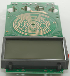

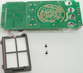
Two more screws and it was loose.
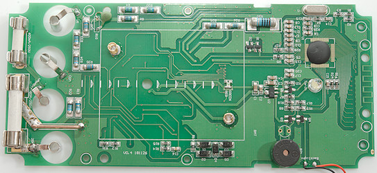
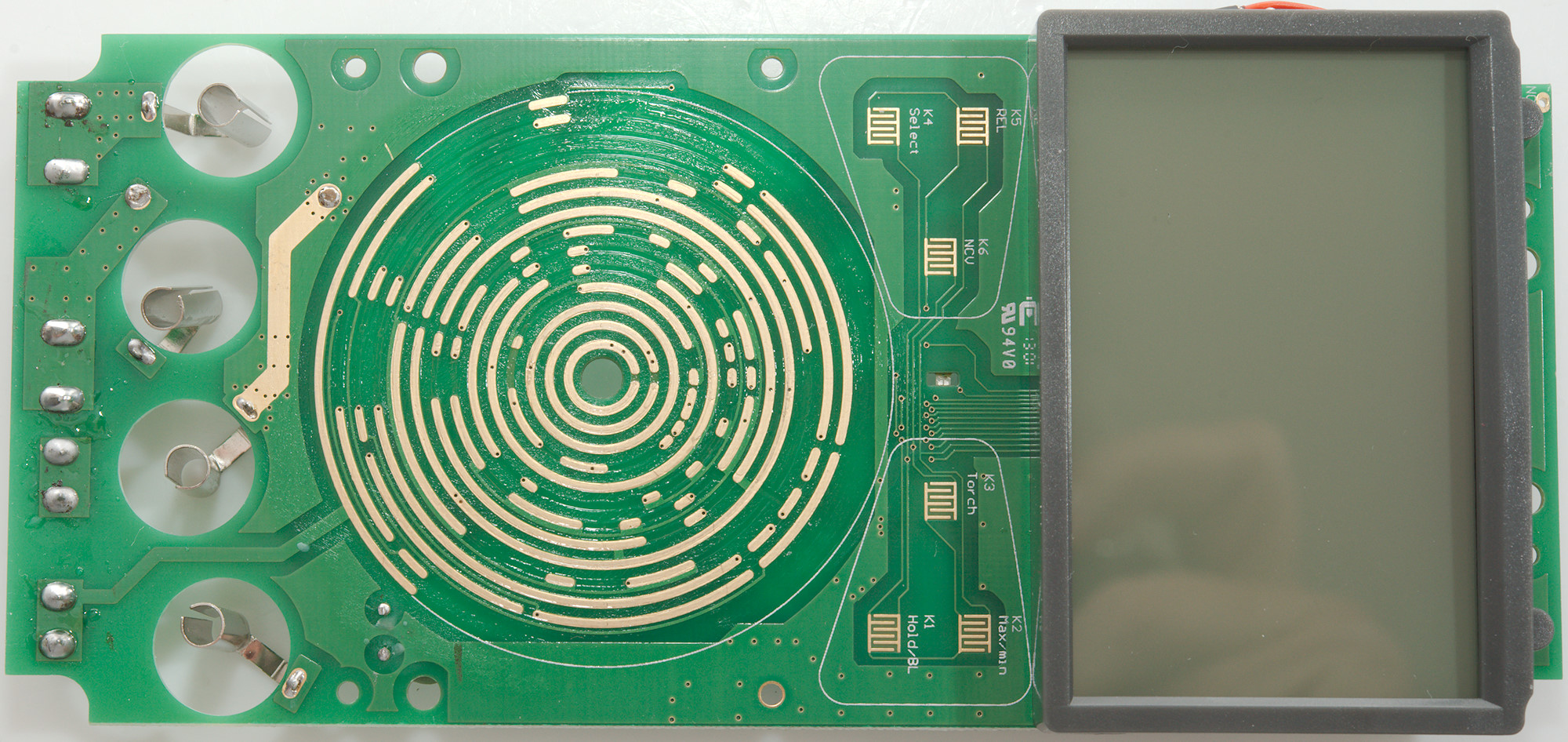
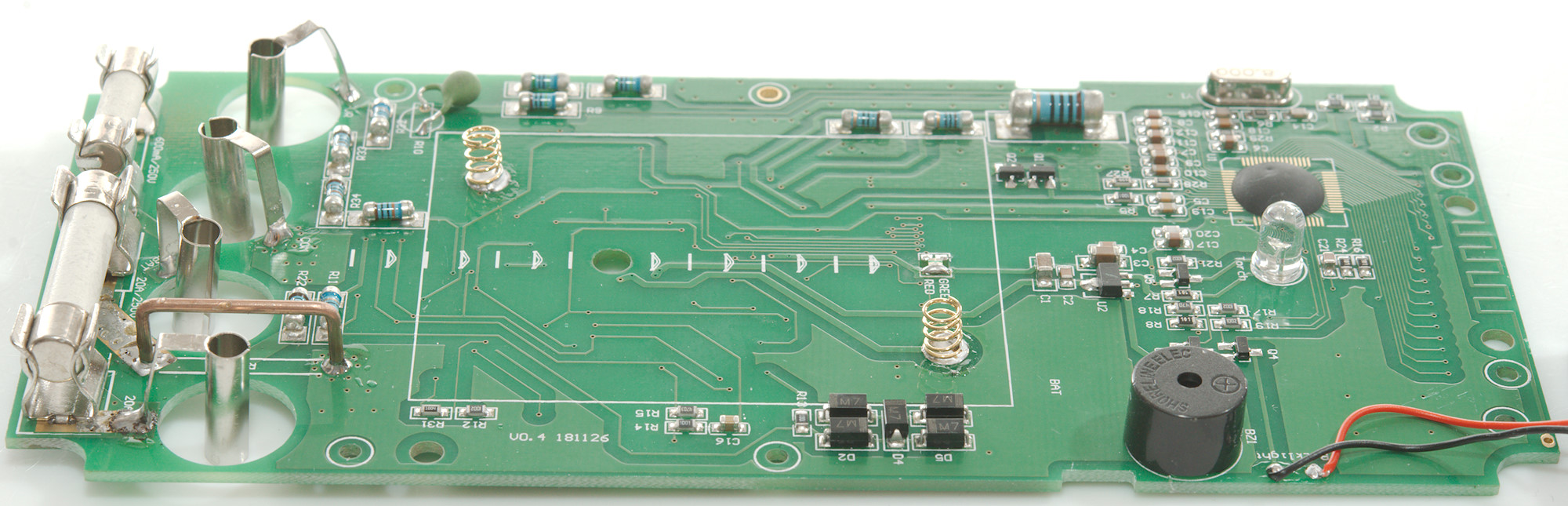
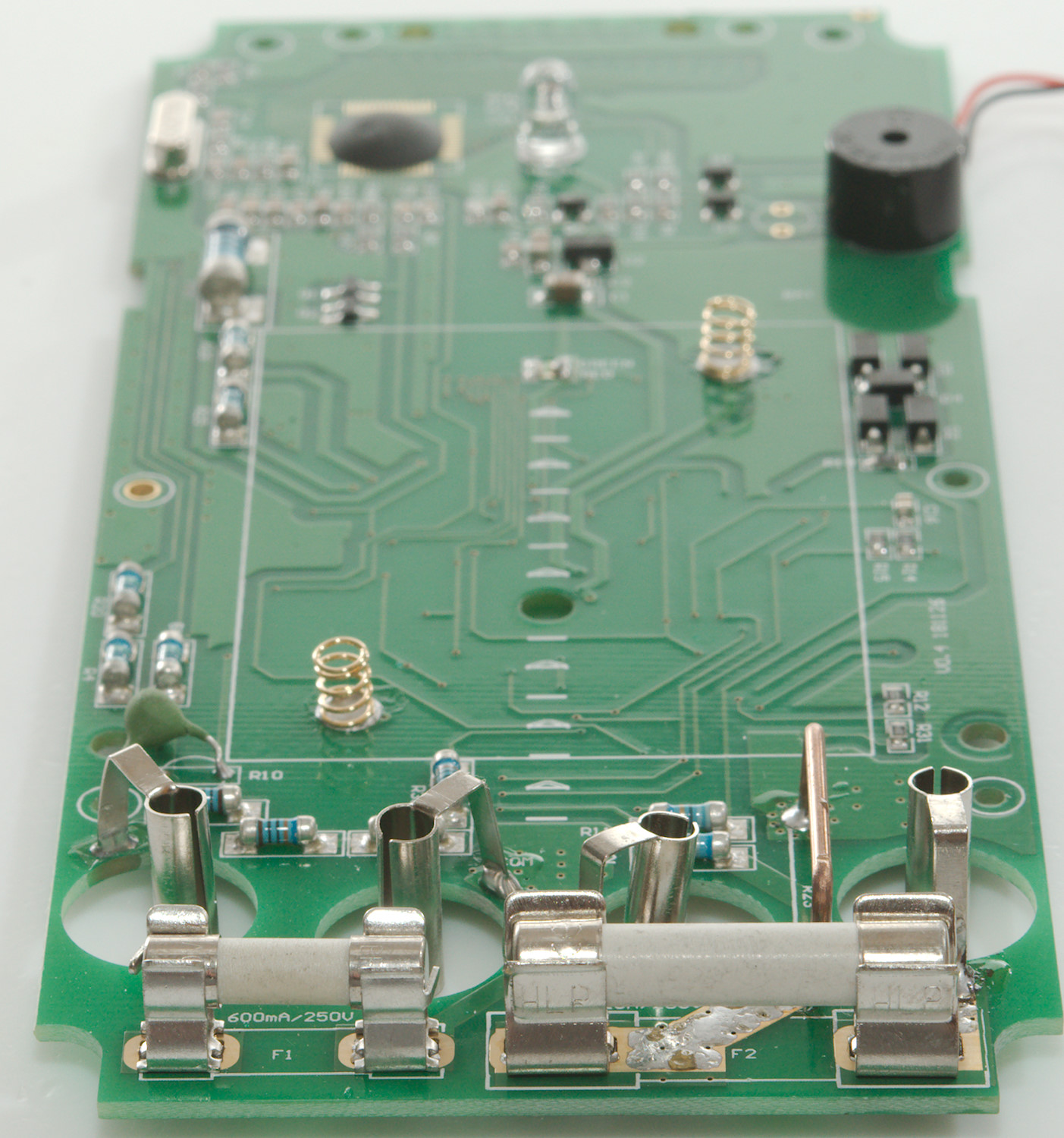
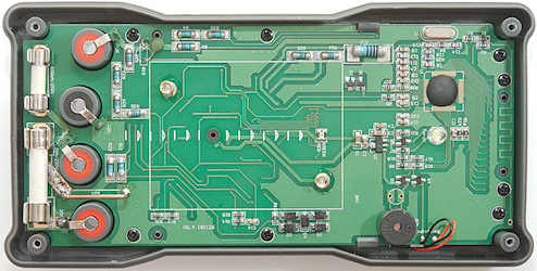
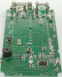
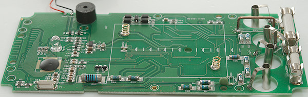
All parts are on this side. The 600uA shunt (R1: 99ohm) is next to the mA shunt (R22: 1ohm), only the uA shunt is protected by the 5 diodes (D1..D5). I was a bit curious about the 12V test resistor, it must handle 1.5W, it is a larger resistor (R20: 100ohm), 9V load is next (R26: 910ohm) and then 1.5V (R25: 180ohm), they are all placed after the 0.6A fuse, but it will not protect them from overload. The voltage from these resistors goes to a voltage divider (R31 & R12: 1M & 10K), the output goes directly to the main chip.
The input configuration on the V etc. input is a bit special, it has the typical 10Mohm (R4 & R20: 2x5Mohm), a 1Mohm (R9: 1Mohm), a PTC protected (R10: PTC) and a 800kOhm (R32..R35: 4x100kOhm). Both the 10Mohm and 1Mohm is directly connected to the main chip in all position of the range switch, this is the explanation of the input impedance.
The PTC is used together with a transistor pair (Q1 & Q2) in capacitance, 600ohm, frequency, temperature and frequency out. This goes to the main chip through a resistor (R5: 1kOhm).
There is no microprocessor or diode collection in the meter, this means the main multimeter chip is dedicated/programmed for this meter and it must have electronic calibration build in. There is a voltage regulator (U2) and transistors for Buzzer, backlight and flashlight (Q3, Q4 and Q5).
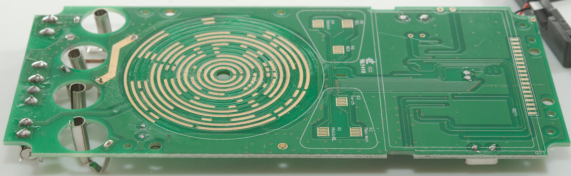
At the top of the circuit board is the NCV antenna.
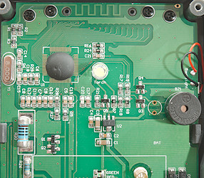
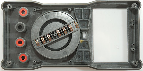
Closeup of the top part.
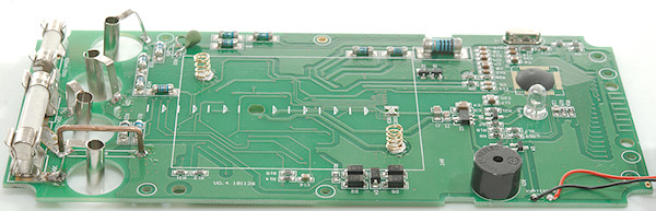
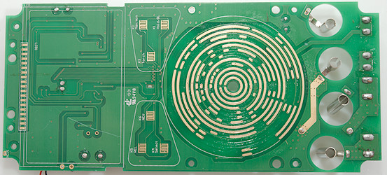
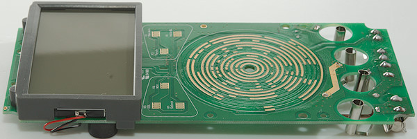
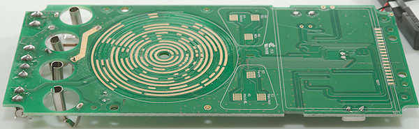
This side only has pads for the range switch, LCD and buttons. The indicator LED is mounted on the other sides and lights through a hole in the circuit board.
Conclusion
This is a cheap meter and as usual with cheap meters they do not live up to their CAT rating, 250VAC fuses and maximum 500V in AUTO mode do not match with a 1000V CAT rating. A single 1Mohm resistor to handle the full input voltage is also wrong.
With that said the meter do have a lot of functions and do most of it fairly well, but there are some omissions. I do not see a big reason for a manual range meter, most auto ranging meters can easily be locked in a range when needed. The low input impedance is a huge disadvantage for electronic use, but it can be a advantage for other measurements.
Notes
How do I review a DMM
More DMM reviews