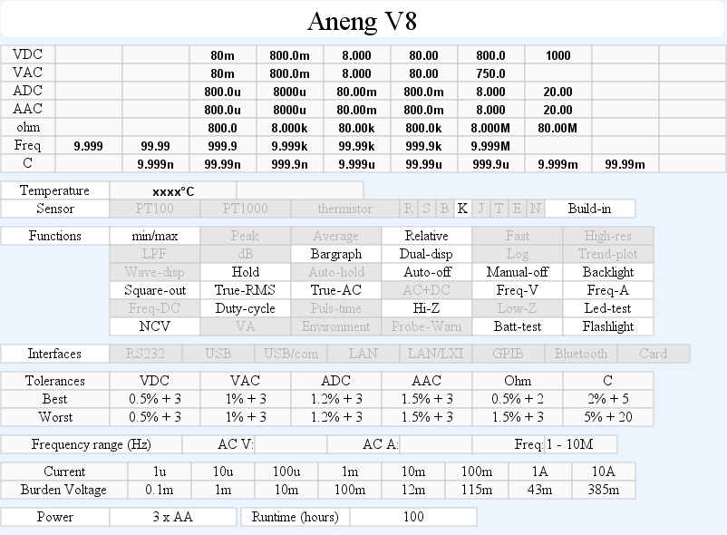
DMM Aneng V8
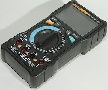
This is a cheap DMM with all common function.
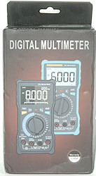

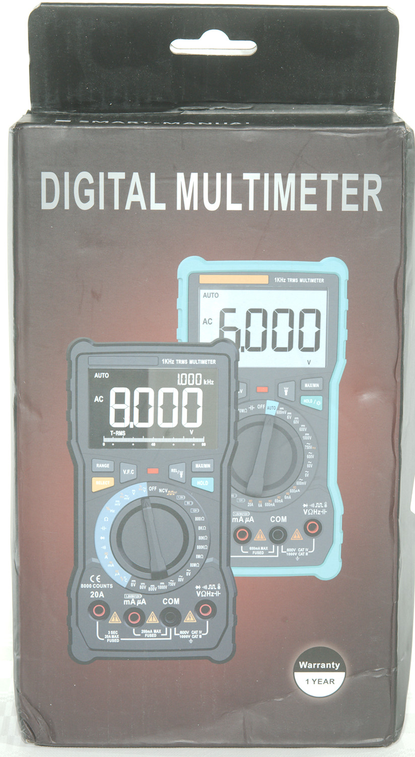
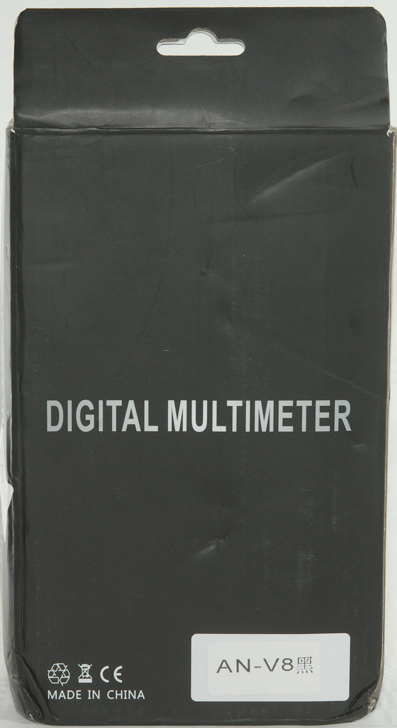
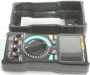
The box for the meter is designed for both the V7 and V8 meter.
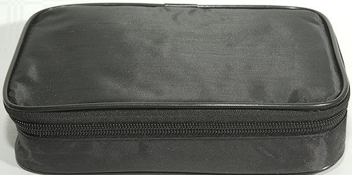
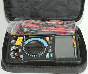
Inside the box is a pouch with everything in it, except the manual.
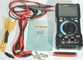
The package included the DMM, a pair of standard probes, the universal probes, a thermocoupler and a manual in addition to the pouch.
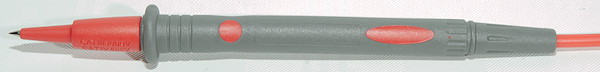
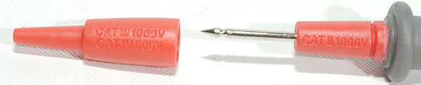
The probes are unbranded, has removable tip covers and is rated for CAT II 1000V, to CAT IV 600V
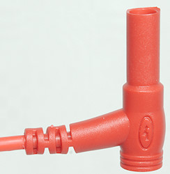
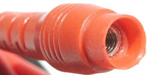
The plug is shrouded.
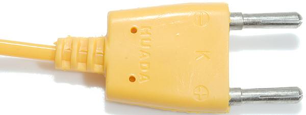
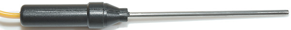
The thermocoupler is designed for insertion into stuff and is with a dual banana plug connector.
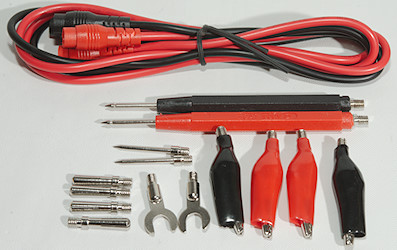
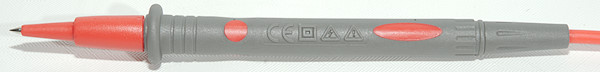
The universal probes can be assembled to many different configuration, they are not high quality, but very useful.
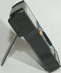
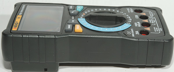
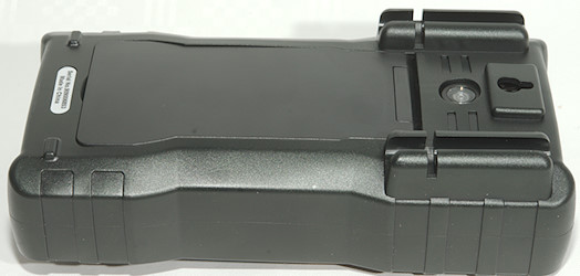
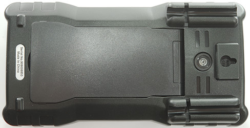
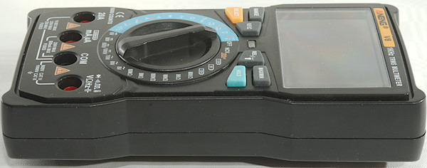
When using the tilting bale it is possible to turn the switch, but not use the buttons with one hand.
Display
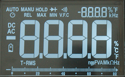
All the segments on the display. There is both bargraph and secondary display
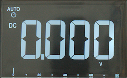
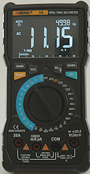
Typical screen during usage with bargraph.
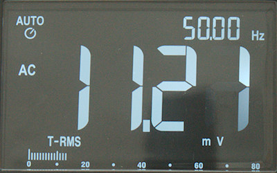
In AC modes the secondary display is used for frequency.
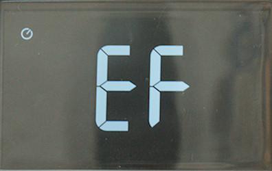
The NCV mode shows the usual EF (Electric field) on the display and change to bars when a actual field is detected. The led below the display will flash red and the buzzer will also sound.
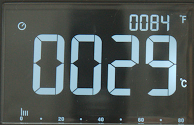
In temperature mode it shows both Celsius and Fahrenheit at the same time.
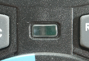
Between the buttons is a led that will show red in continuity and NCV mode.
Secondary display functions, value after / is secondary value:
VAC: VAC/frequency, frequency/duty-cycle
Frequency: frequency/duty-cycle
Current: DCA, ACA/frequency, frequency/duty-cycle
Temperature: Celsius/Fahrenheit
Functions
Buttons:
- Range: Select and change manual range (Used in auto range position), hold down to return to auto range.
- V.F.C.: Apply a high pass filter to AC voltage, it will also lock the range to 750VAC.
- Select (Yellow): Select the ranges printed with yellow.
- Rel: Shows values relative to current value, will also select manual range. Press again to disable. Hold down for flashlight.
- Max/min: Starts recording maximum and minimum value, press to select between max/min, hold down to disable
- Hold (Blue): Freezes the display reading.
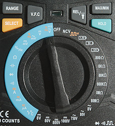
Rotary switch:
- Off: Meter is turned off
- NCV: Non Contact voltage or electric field detection.
 : Frequency output from 50Hz to 5000Hz, use SELECT to step the frequency.
 : 12V battery test
 : 9V battery test
 : 1.5V battery test.
- 6 x ohm: Manual ohm ranges.
- 3 x VAC: Manual VAC ranges
- 4 x VDC: Manual VDC ranges.
- °F °C: Temperature range.
- uA: Micro ampere DC and AC with frequency and duty cycle for AC
- mA: Milli ampere DC and AC with frequency and duty cycle for AC
- A: Ampere DC and AC with frequency and duty cycle for AC
 : Continuity
 : Diode
 : Capacitance
 : Resistance
- mVDC: Millivolt DC
- mVAC: Millivolt AC with frequency and duty cycle.
- VDC: Volt DC
- VAC: Volt AC with frequency and duty cycle.
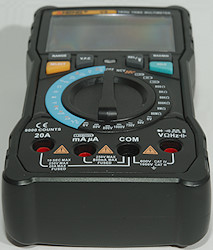
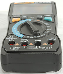
Input
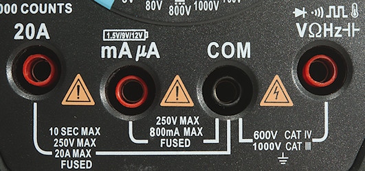
- 20A: High current, it can only withstand 10+ ampere for a short time (Fuse is 10A).
- mAuA: The lower current ranges, the selector switch will change between two different shunts (Fuse is 600mA).
- COM: The common terminal for all ranges.
- xxx: All other ranges.
The terminals fairly retracted into the meter.
Measurements
- Volt and frequency
- At 100mVrms input frequency input range is from 1.1Hz to 6MHz
- At 1Vrms input frequency on VAC range is from 1Hz to 40kHz
- Frequency input requires a zero crossing on both logic and VAC input
- Duty cycle works from 2% to above 99% at 100kHz with 1Vpp, precision is within 0.2
- 1 VAC is 5% down at 1.9kHz (RMS will not work at the frequency), AUTO and manual is similar.
- 7 VAC is 5% down at 500Hz with VFC (RMS will not work at the frequency), AUTO and manual is similar.
- When using VFC the range is locked to 750VAC, it cannot be select in manual voltage ranges.
- Max/min needs less than 200ms to capture a voltage, but need many pulses for it.
- Input impedance is between 10 and 11Mohm on DC and AC
- Input impedance is high on mVDC (AC is limited to 10Mohm) and will drop to a few kOhm above 2V.
- Current
- 20A range will give audible alarm at 10A
- Overload protection in uA and mA: 0.8A/250V 5x20mm ceramic fuse
- Overload protection in A: 20A/250V 6x30mm ceramic fuse and 20A/250V fuse.
- Ohm, Continuity, diode and capacitance
- Ohm needs about 1.8s to measure 100ohm in auto range and 0.7s in manual range
- Ohm is 1.0V open and 0.38mA shorted
- Continuity is quick (Below 30ms).
- Continuity beeps when resistance is below 50ohm.
- Continuity is 1.0V open and 0.38mA shorted
- Diode range uses 3.2V, max. display is 3.000V at 0.12mA, max. current is 1.6mA shorted
- 10uF takes about 5 seconds to measure.
- 11000uF takes about 10 seconds to measure.
- No overload protection is rated.
- Miscellaneous
- 12V battery test uses a 1200ohm resistor
- 9V battery test uses a 910ohm resistor
- 1.5V battery test uses a 150ohm resistor
- Frequency output has the following frequencies: 50, 100, 200, 300, 400, 500, 600, 700, 800, 900, 1000, 2000, 3000, 4000, 5000Hz
- Current consumption of meter is 26mA (With backlight it is 29mA).
- Meter works down to 2.4V where it turns off, battery symbol show at 2.9V.
- Reading is stable within a few counts until it turns off.
- Backlight fades slowly with falling voltage, display is nearly unreadable at 2.5V
- The meter usual need a couple of display update to reach the final value.
- Viewing angle is good, except from the top.
- Display updates around 3 times/sec
- Flashlight do not turn automatic off, but will turn off when the meter turns off.
- Will automatic turn power off in about 15 minutes.
- Standard probes can nearly be pushed fully down.
- Weight is 416g without accessories, but with rubber sleeve and batteries.
- Size is 176 x 91 x 47mm with rubber sleeve.
- Probes
- Standard probe resistance 40mOhm for one.
- Standard probe wire is 79cm long.
- Custom probe resistance is 56mOhm
- Custom probe wire is 86cm long
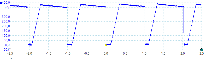
A look at the capacitance measurement waveform.
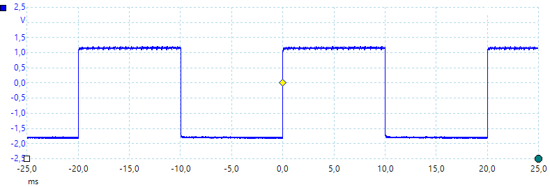
50Hz frequency output, it swings around zero.
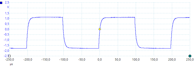
5000Hz frequency output.
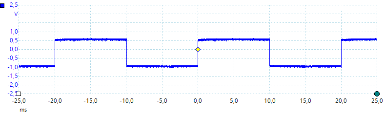
50Hz output loaded with 100kohm halved the output voltage
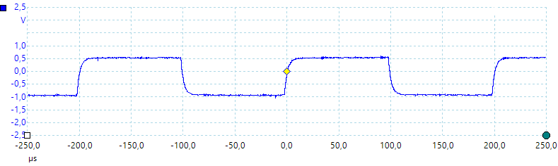
5000Hz output with 100kOhm load.
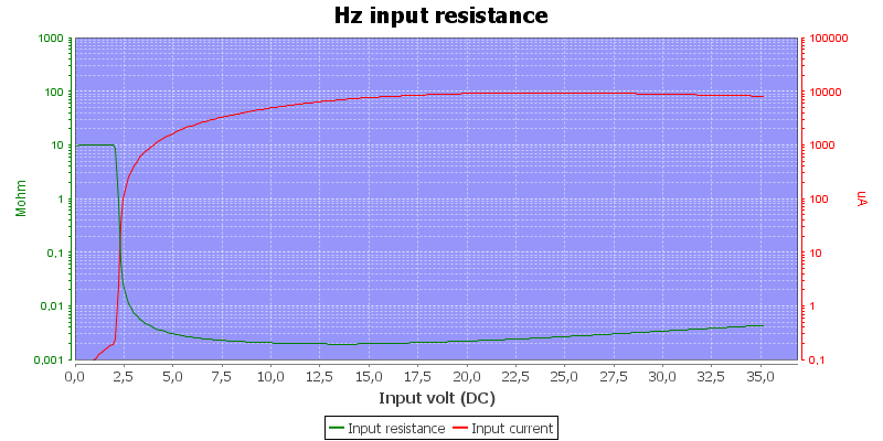
Frequency input resistance depends on input voltage.
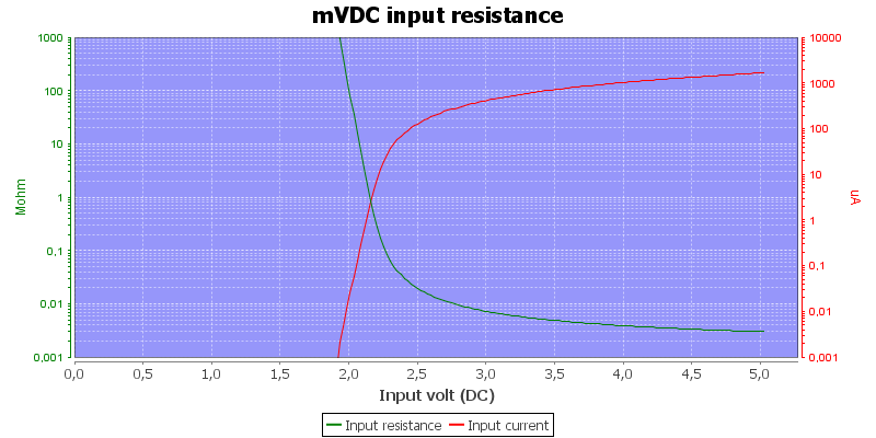
The mVDC range is high impedance, until the protection clamps, mVAC is limited to 10Mohm.
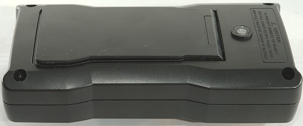
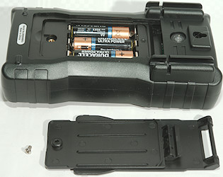
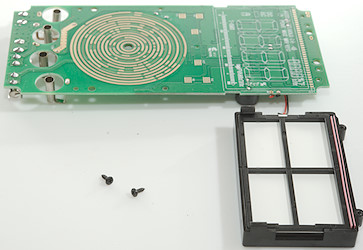
Tear down
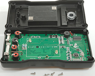
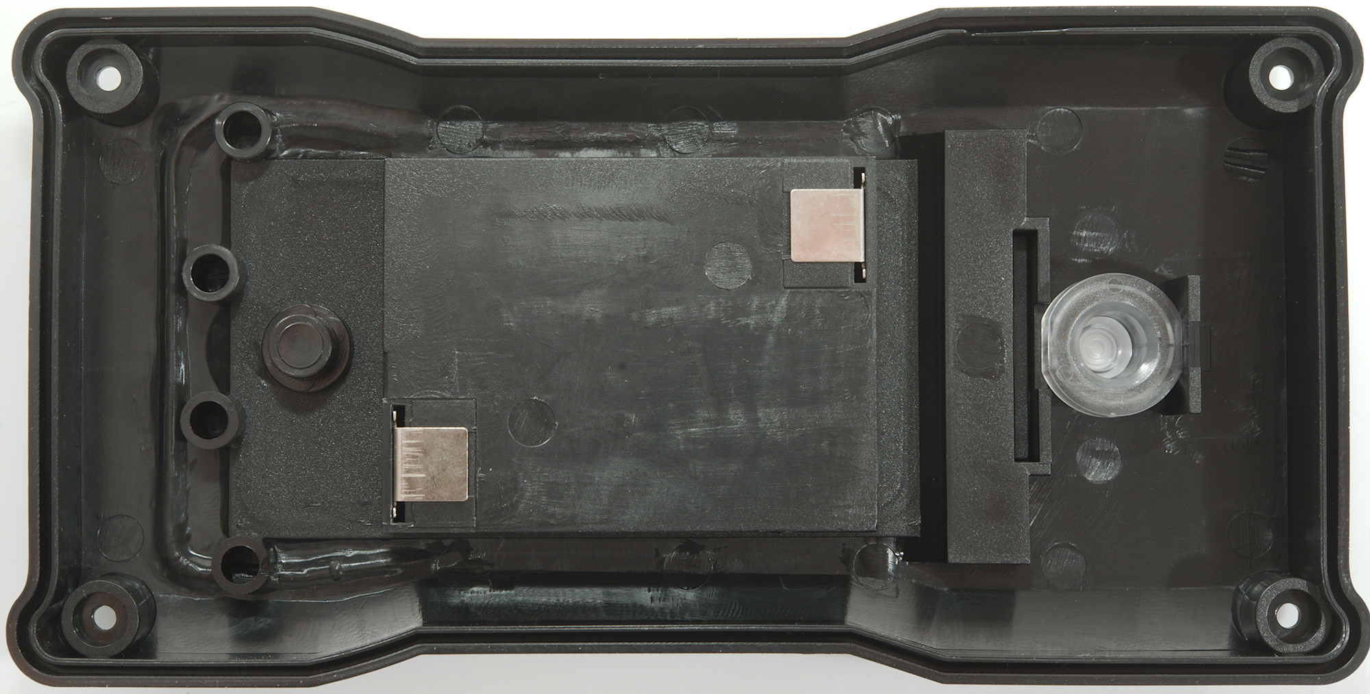
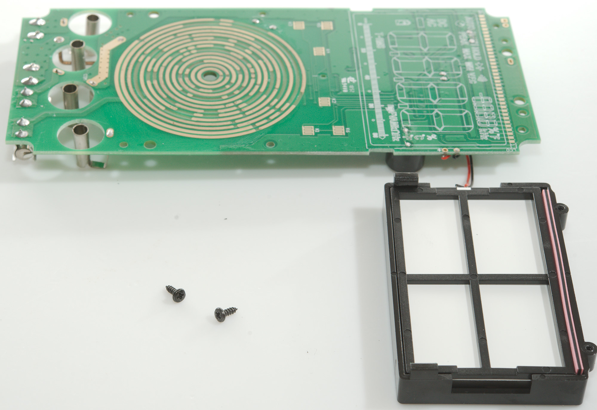
I had to remove four small screws to open the meter.
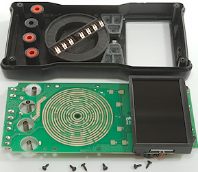
And 6 more to remove the circuit board.
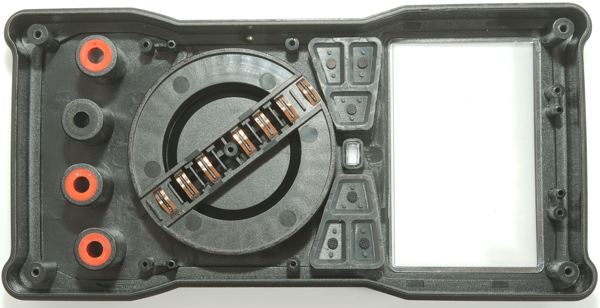
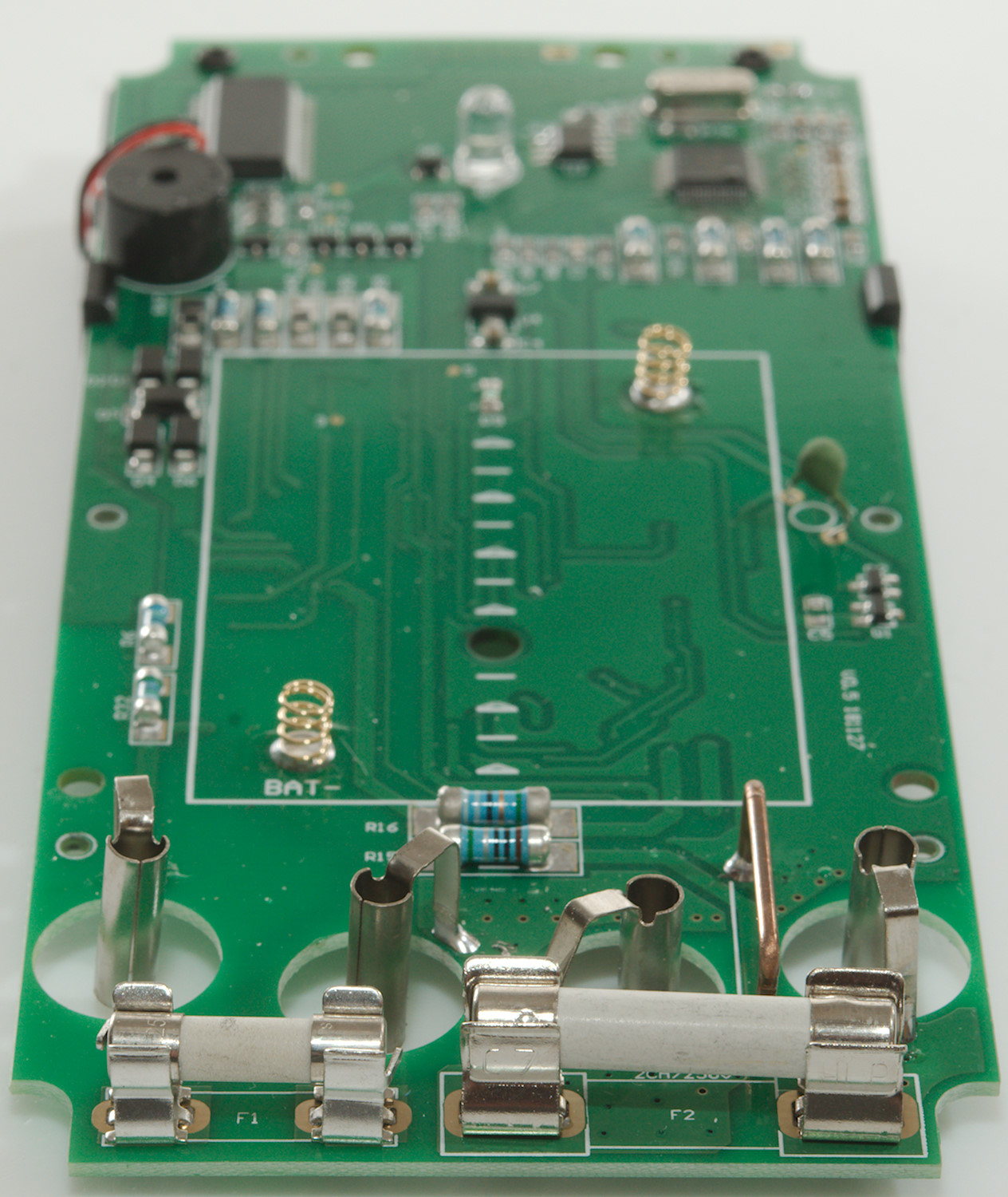
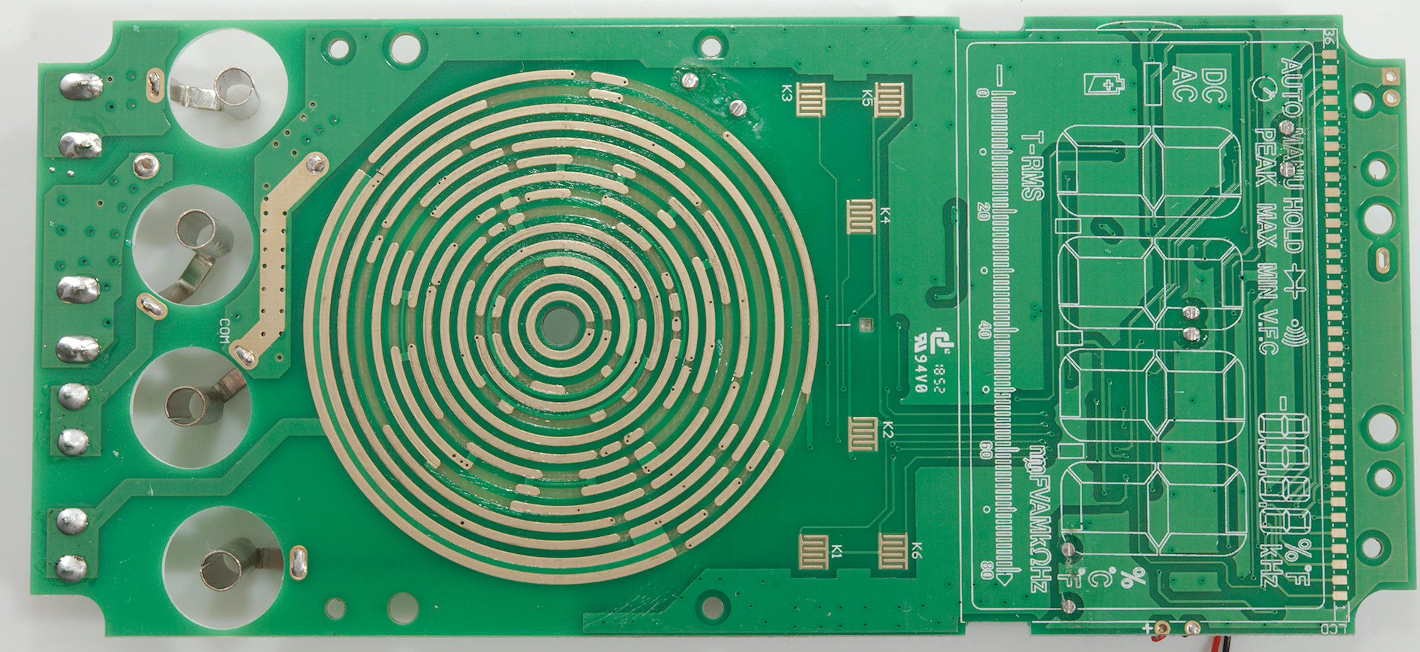
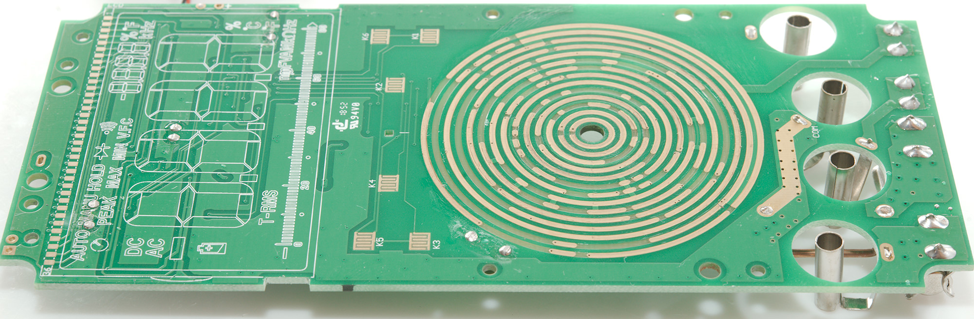
The range switch has 7 connections.
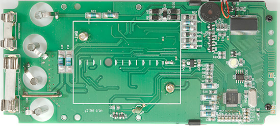
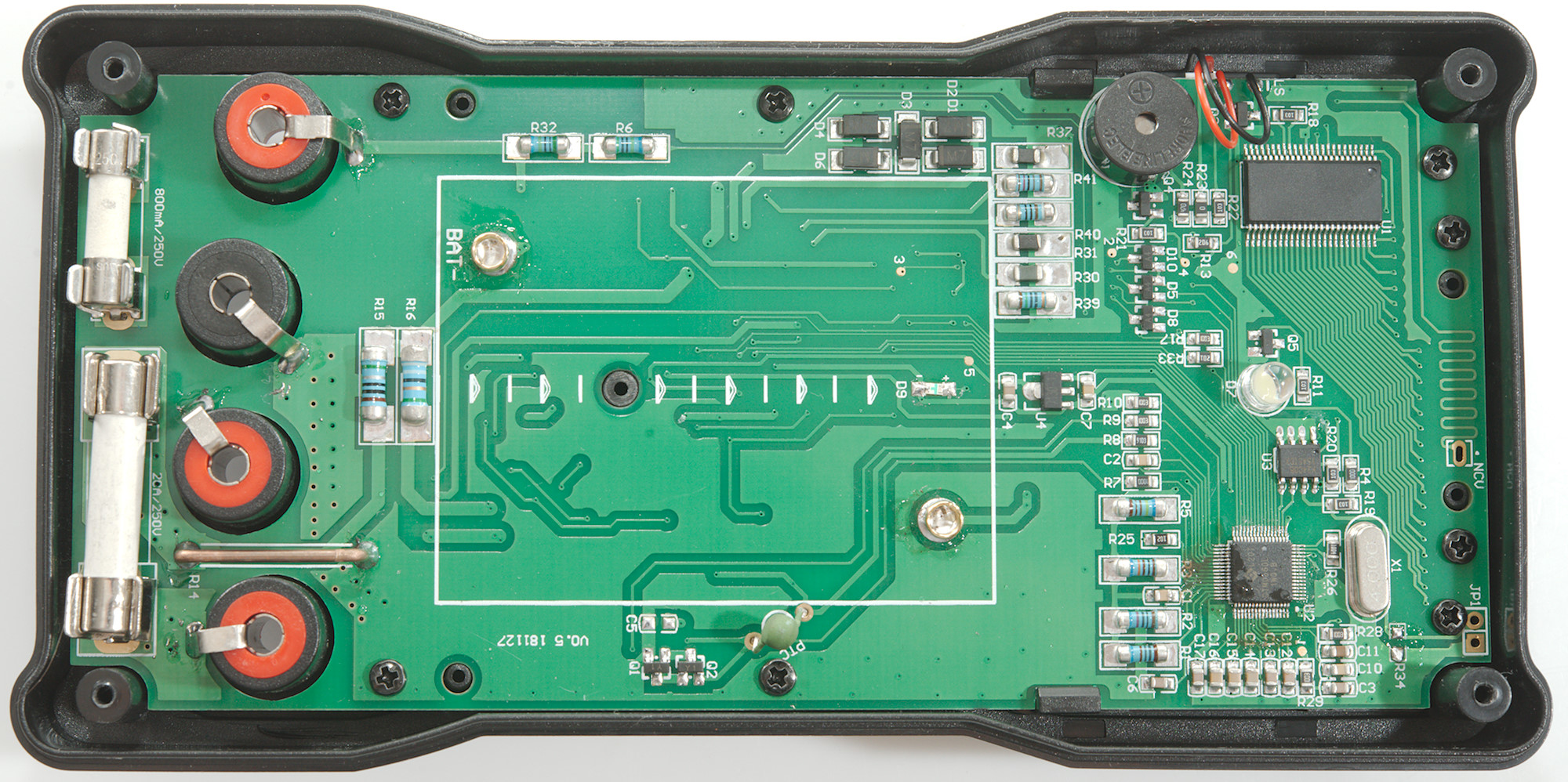
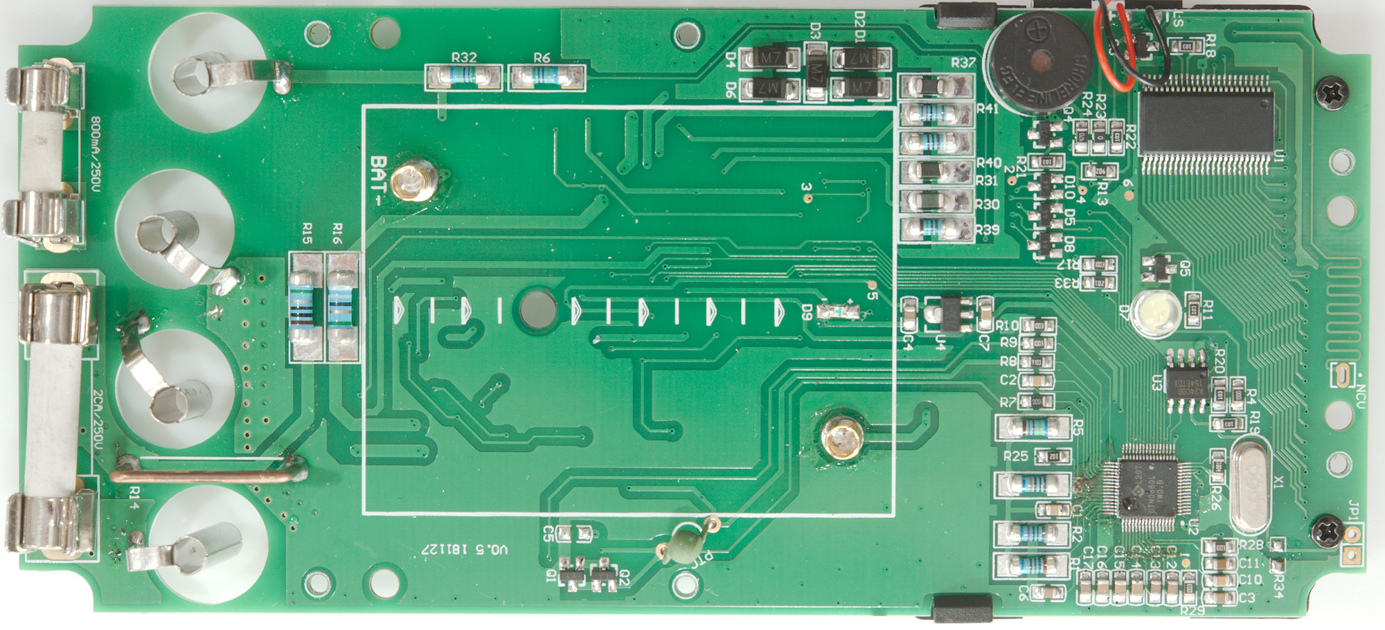
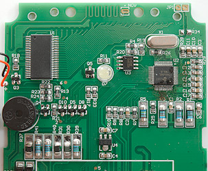
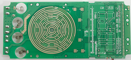
All the electronic is on this side. The uA shunt (R16: 99ohm) is in series with the mA shunt (R15: 1ohm), the five diodes (D1, D2, D3, D4, D6) is across the input voltage, but after the fuse. The voltage from the current shunts goes to a resistor (R9: 100kOhm) and the to the main chip. The voltage input has two resistors in series (R6 & R32: 2x5Mohm) going directly to the main chip.
The battery tester for 1.5V (R36: 150ohm), 9V (R40: 910ohm) and 12V (R41: 1200ohm) do not have any overload protection, except the fuse and that is not very safe because the V input is directly connected to the resistors (mA & V input is shorted together through the fuse in these 3 ranges).
This meter has the very common small SMD resistor (R8: 910kOhm) that must handle overload on a lot of ranges: mVDC, mVAC, frequency, resistance, capacitance, diode, continuity and temperature. For resistance, capacitance, diode, continuity the PTC and the transistor pair (Q1 & Q2) protection the current output, but it is also connected in mVDC, mVAC, frequency and temperature. Frequency output is through a resistor (R17: 100kOhm), this will give a fair amount of protection, but not against high voltage.
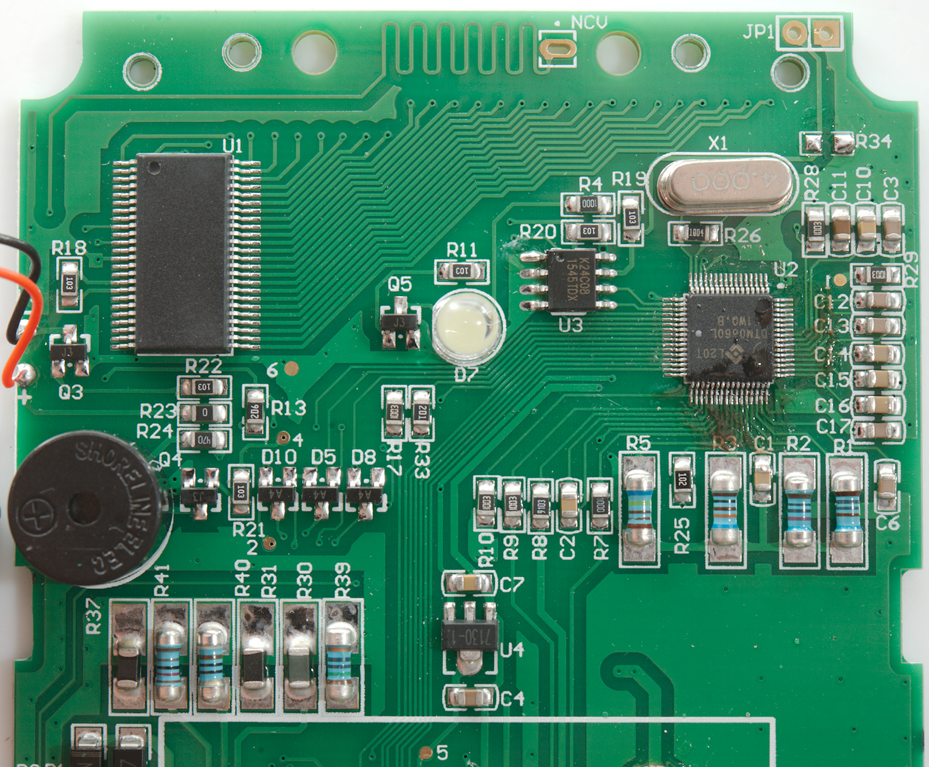
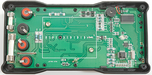
The main chip (U2: DTM0660L) and its EEPROM (U3: K24C08) is a well proven solution is cheap meters, this meter also adds a display driver (U1: unmarked) for the inverted display. There is transistors for backlight (Q3), flashlight (Q5) and buzzer (Q4), in addition to a voltage regulator (U4: 7130). There are a few diodes (D5, D8, D10), they may be used for rotary switch encoding to the chip.
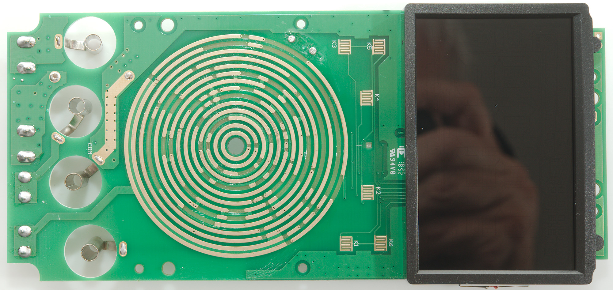
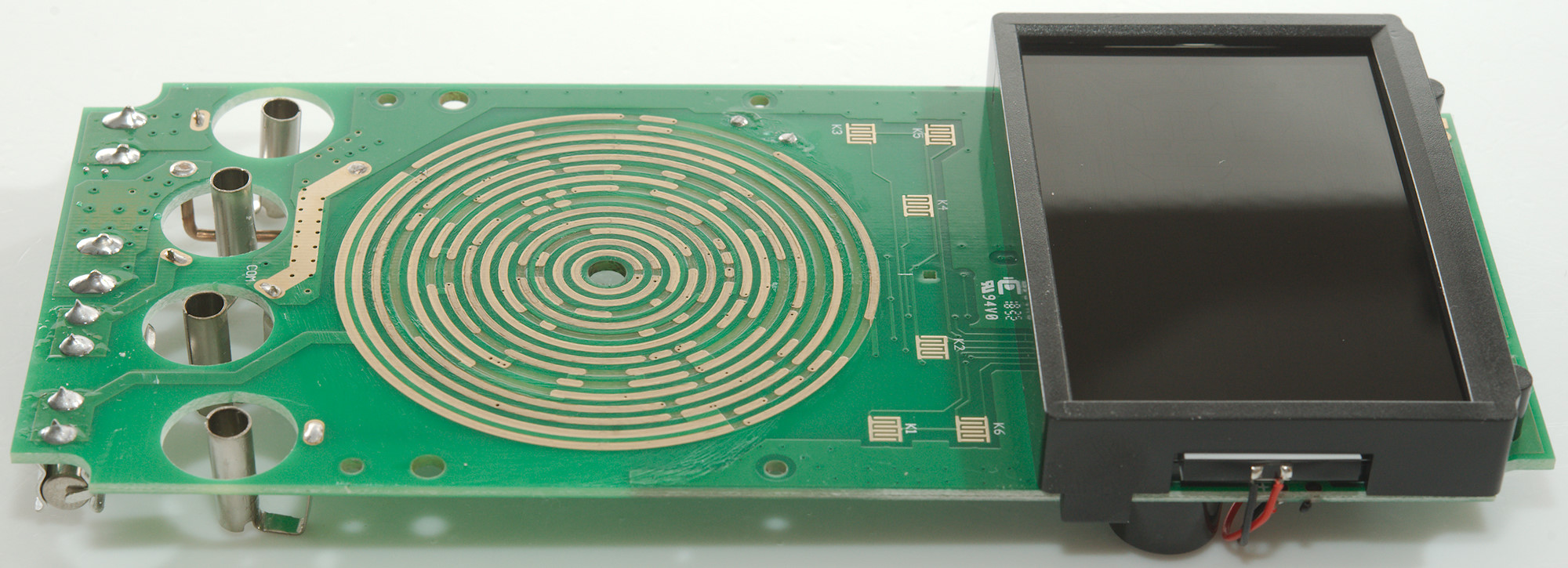
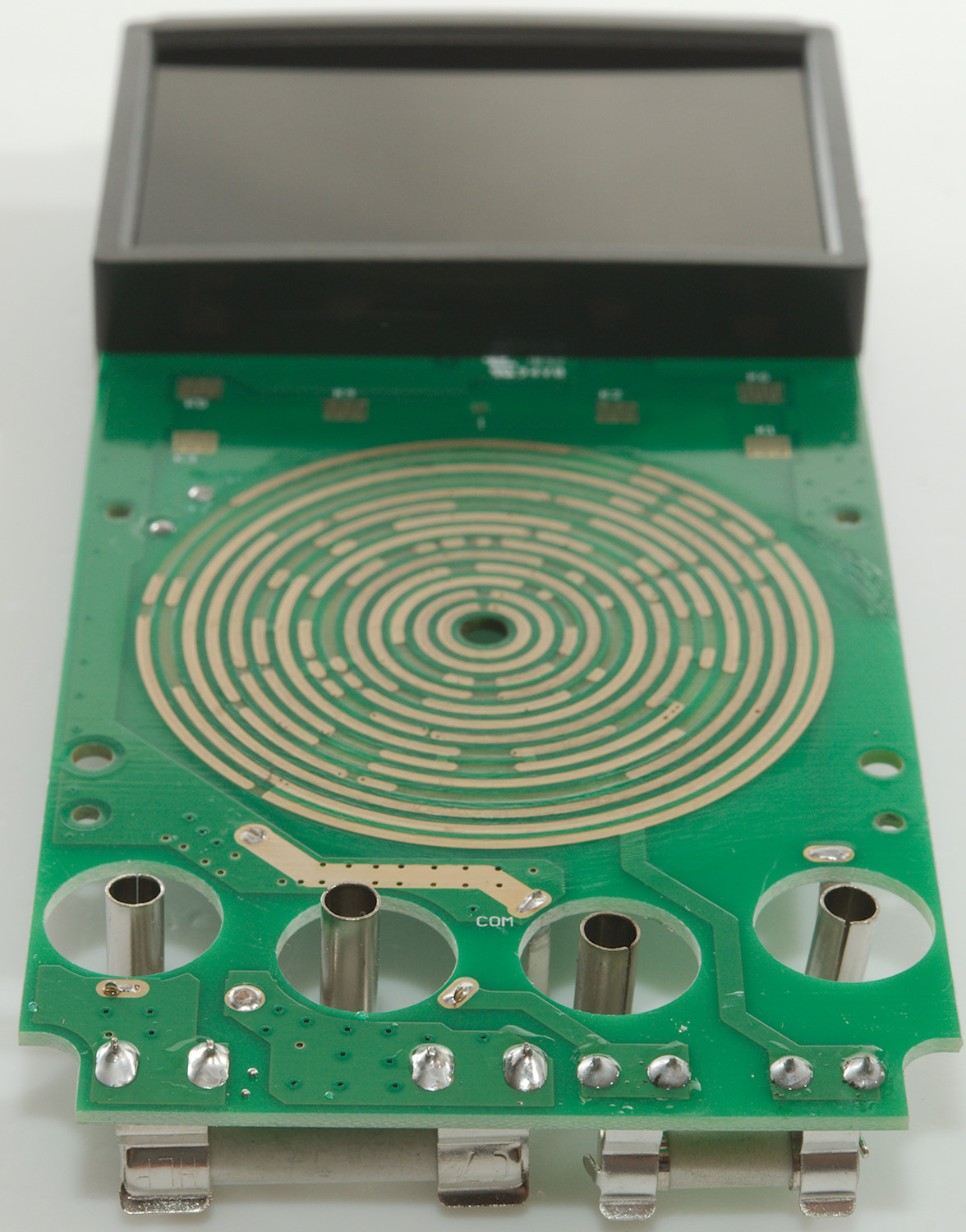
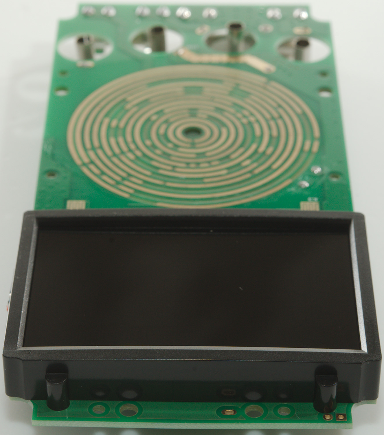
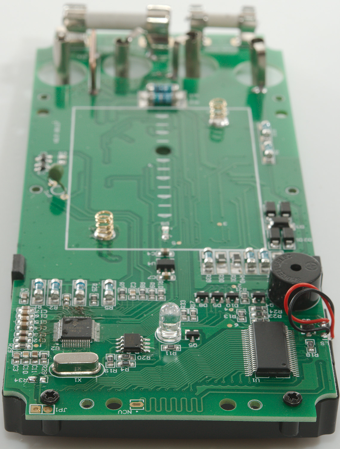
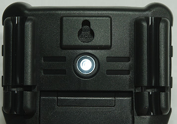
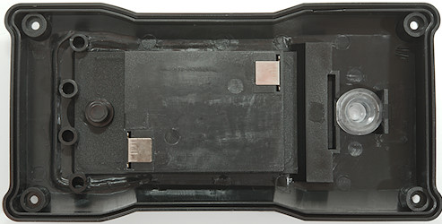
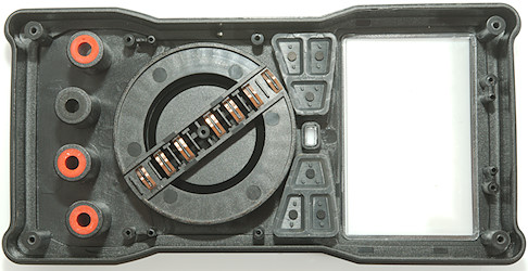
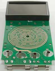
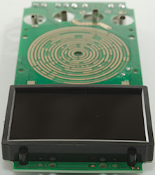
The NCV antenna is at the top.
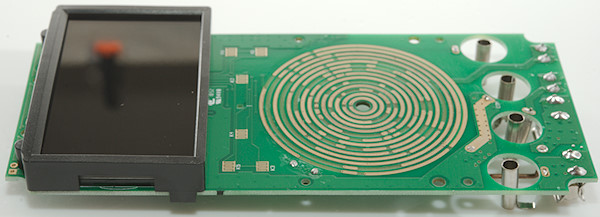
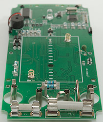
A closeup of the top part.
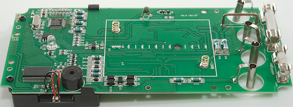

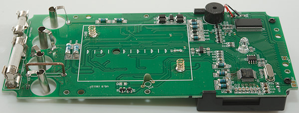
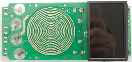
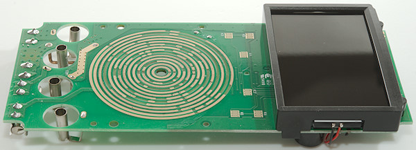
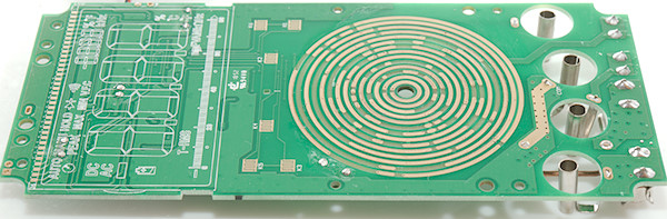
This side only has the pads for the rotary switch, the buttons and the LCD. The LCD layout is printed on the circuit board.
Conclusion
This is a cheap meter and as usual with cheap meters they do not live up to their CAT rating, 250VAC fuses do not match with a 1000V CAT rating. A small SMD resistor that must withstand 1000's of volt is not realistic either. Or the battery load resistors that is directly connected to the V terminal when battery test ranges is selected.
With that said the meter do have a lot of functions and do most of it fairly well. The manual range is a bit silly, it is easy enough to select a range manually when needed with the RANGE button.
Notes
How do I review a DMM
More DMM reviews