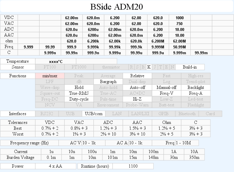
DMM BSide ADM20
This is the one of the best BSide meters, it includes a computer connection.
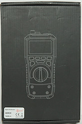
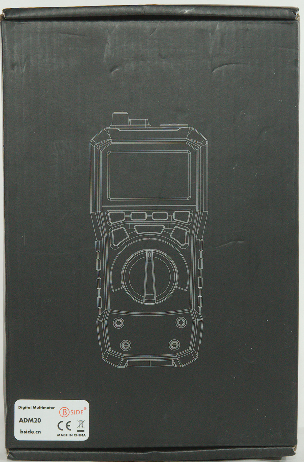
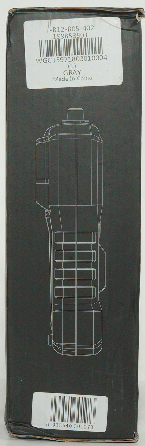
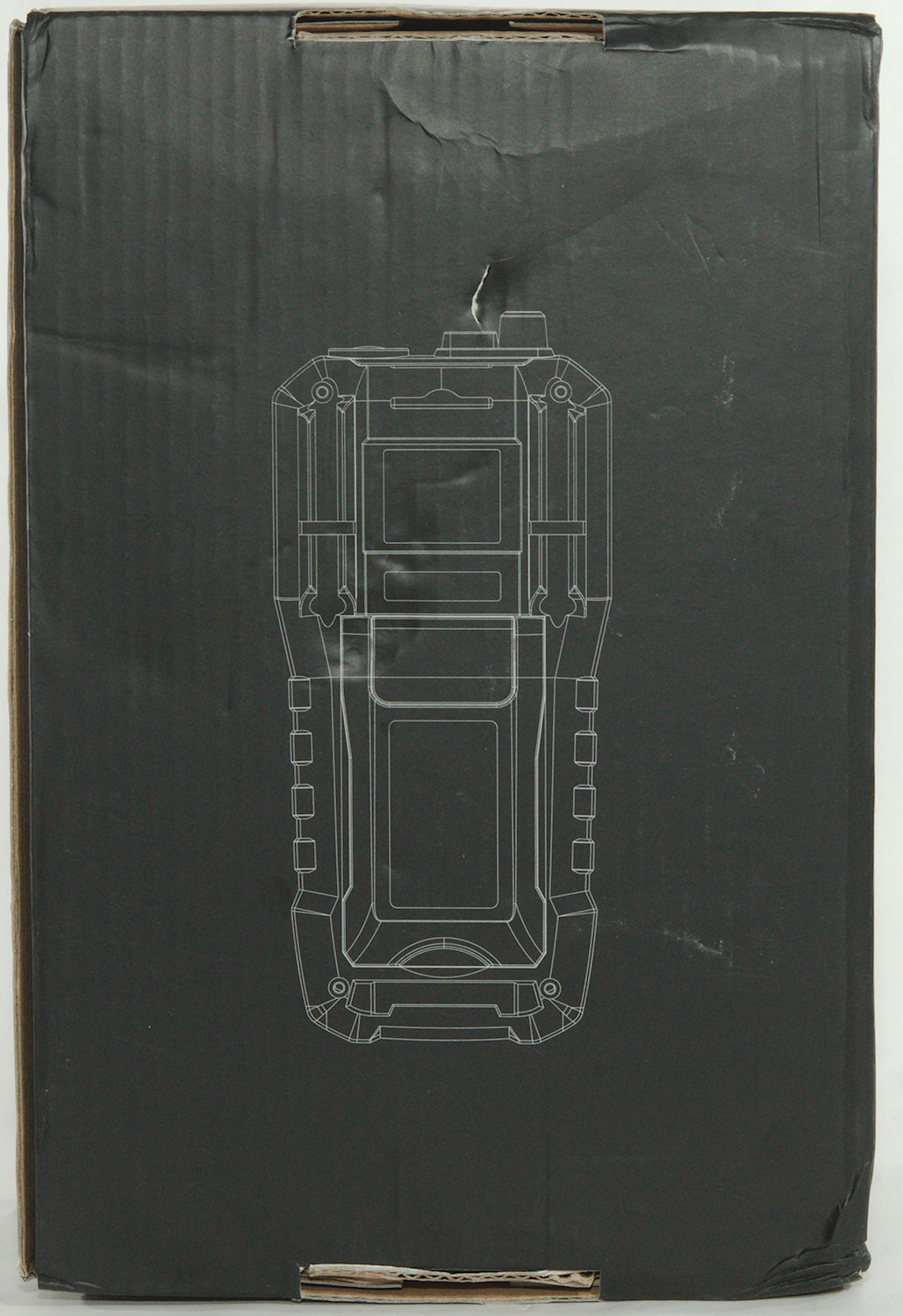
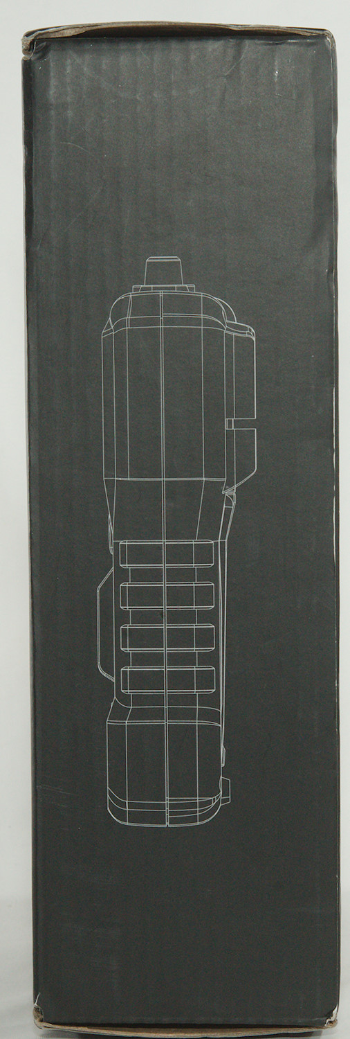
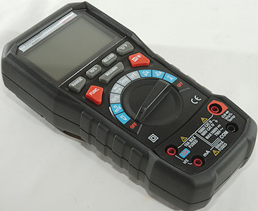
The meter arrived in a cardboard box without any branding on it but the drawing nearly matches the meter.
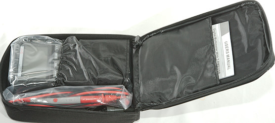
Inside the box was a pouch with the meter and everything else.
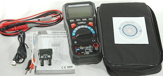
This means the meter, two probes, a thermocoupler, a transistor tester adapter, a USB cable, a CD and a manual.
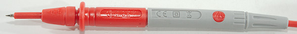
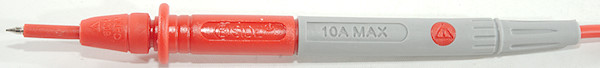
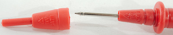
Probes are branded with BSide and rated for 1000V, CAT II without tip covers and CAT III with covers.
The cable is rated for 10A, but that is very optimistic with the resistance I have measured.
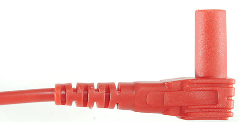
The plug is fully shrouded with short shroud.
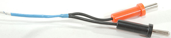
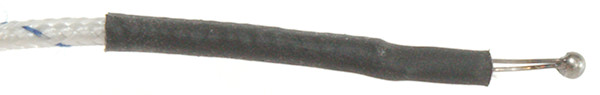
A standard cheap thermocoupler with a two banana plugs.
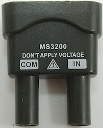
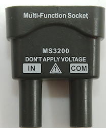
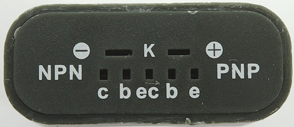
The transistor test plug can also be used for thermocouplers.
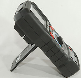
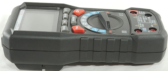
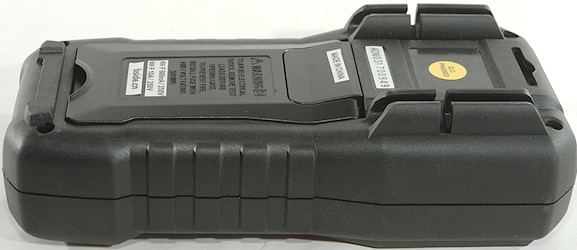
The meter is heavy and the tilting bale can hold it while the range switch is used or the buttons is pressed.
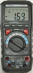
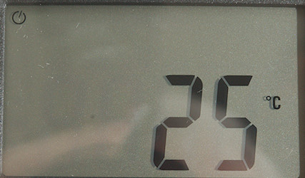
Display
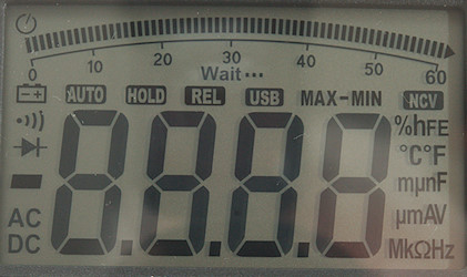
The above picture shows all the segments on the display, a few of them are not used.
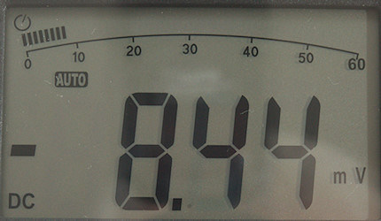
Normal DC voltage with voltage and bargraph. The bragraph always goes to 60 for ranges with maximum at 99 it will be stuck at maximum from 60 and up.
The bargraph is included on most ranges, but there are some exception.
Functions
Buttons (Range selection and a few other are remembered):
- Range: Switch to manual range and select range, hold down to activate automatic ranging again.
- Hz %: Select frequency or duty cycle in AC voltage and AC current modes. In Hz mode it selected duty cycle.
- Rel/USB. A short press will remember current value and show further values relative to this, press again to disable. Holding it down will enable the usb interface.
- °C/°F: Change between Celsius and Fahrenheit in temperature mode.
- Func (Red): Select AC/DC and ohm/continuity/diode/capacitance
- Max/Min: Supposed to capture maximum and minimum values (Do not work reliable), it changes between max/min/max-min., hold down to disable.
- H: Freeze the display, press again to release. Hold down to turn on background light.
REL and MAX/MIN will disable auto ranging.
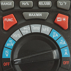
Rotary switch:
- Off: Meter is turned off.
- V: Measure DC and AC voltage, use Hz button for frequency and duty cycle.
- mV: Measure DC and AC millivolt, use Hz button for frequency and duty cycle.
- Hz%: Logical frequency and duty cycle, this has much higher bandwidth.
 : Resistance, continuity, diode and capacitance.
- Temp: Measure temperature with a thermocoupler.
- hFE: Transistor tester, requires the supplied adapter.
- uA: The uA range, use Hz button for frequency and duty cycle.
- mA: The mA range, use Hz button for frequency and duty cycle.
- A: The A range, , use Hz button for frequency and duty cycle.
- Off: Meter is turned off.
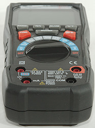
Input
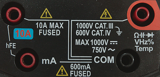
- A: High current, maximum current is 10A, this is also used for the hFE adapter
- mAuA: The lower current ranges, this is also used for the hFE adapter
- CON: The common terminal for all ranges.
- xxx: All other ranges.
Measurements
- Volt and frequency
- At 0.1Vrms frequency input (VAC) range is from 2Hz to 1kHz
- At 1Vrms frequency input (VAC) range is from 2Hz to 33kHz
- Frequency input (VAC) requires a zero crossing.
- At 0.1Vrms logical frequency input (Hz) range is from 2Hz to 6MHz
- At 1Vrms logical frequency input (Hz) range is from 2Hz to 46MHz
- Logical frequency input (Hz) requires a zero crossing.
- Duty cycle works from 2% to 99% at 100kHz with 1Vpp, precision is within 0.2
- 1 VAC is 5% down at 2kHz (RMS will not work at the frequency).
- Max/min probably needs about 350ms to capture a voltage, but do not work reliable.
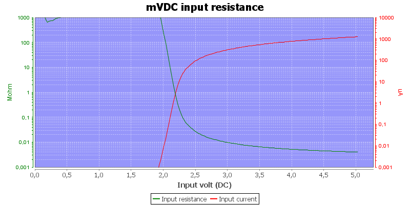
- Input impedance is 10-11Mohm on AC/mVAC/DC
- mV DC has high input impedance up to about 2V
- Frequency input has high input impedance up to about 2V
- Rated overload protection on V ranges 1000VDC 750VAC
- Current
- All current ranges has audible alarm when overloaded.
- Overload protection in uA and mA: 0.6A/1000V 6.3x32mm fuse (The mounted fuse was 250V)
- Overload protection in A: 10A/1000V 6.3x32mm fuse (The mounted fuse was 250V)
- Ohm, continuity, diode and capacitance
- Ohm needs about 2.7s to measure 100ohm
- Ohm is 1.0V open and 0.33mA shorted
- Continuity is very fast (Below 10ms).
- Continuity beeps when resistance is below 50ohm
- Continuity is 1.0V open and 0.33mA shorted
- Diode range uses 3.2V, max. display is 1.5V at 0.74mA, max. current is 1.4mA shorted
- 10uF takes about 4.5 seconds to measure.
- 70000uF takes about 7 seconds to measure.
- Rated overload protection on V ranges 1000VDC 750VAC
- Miscellaneous
- Current consumption of meter is 2mA-2.5mA, the high value is for AC modes (73mA with backlight, usb adds about 0.6mA)
- Meter works down to 2.1V, at 2V it might reset and slightly below that turn off, battery symbol show at 4.7V.
- The meter reading is stable down to about 3V, then it will show a few counts low (With 5V I got 10 count down to 2V).
- Backlight is fades with battery voltage and is just about gone at 2.7V
- The meter need a couple of updates before the reading is fully correct.
- Viewing angle is good
- Display updates around 4 times/sec
- Bargraph updates at same rate as numbers
- Backlight will turn off in 15 seconds
- Will automatic turn power off in about 15 minutes
- Standard probes fits into sockets on meter.
- Weight is 458g without accessories, but with batteries.
- Size is 194 x 93.4 x 54mm.
- Probes
- Probe resistance 126mOhm for one.
- Probe wire is a bit stiff and 100cm long.
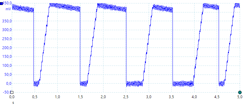
A look at the capacitance measurement waveform when measuring 1uF
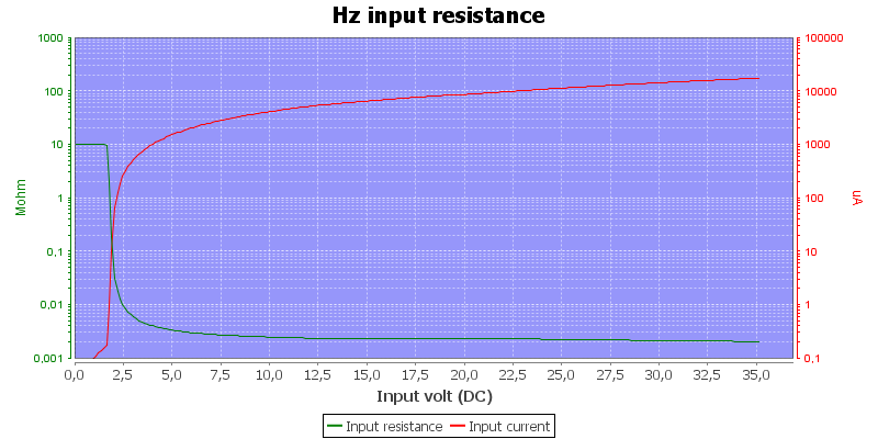
Frequency input resistance, this is similar to mV
10A range will change when heated up, but stays inside tolerances.
min/max do not work reliable.
With high DC voltage AC ranges will jump up/down.
Software
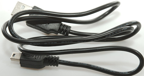
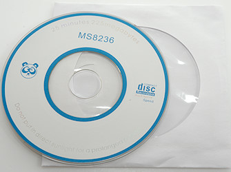
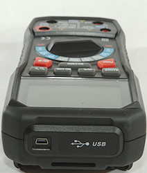
The meter includes a usb cable (Mini) and a small CD with the software and drivers.
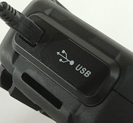
The usb-mini is plugged into the top of the meter.
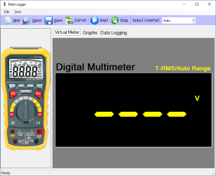
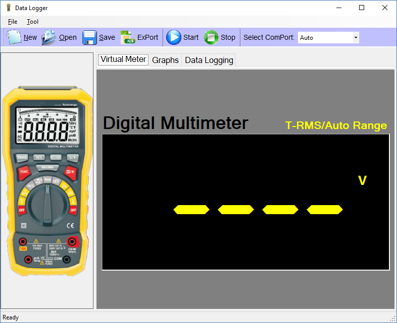
Software installed on my Win10 computer and started. The shown meter is unbranded and uses other colors than ADM20.

Connected to the meter it will replicate the display, but without the bargraph.
I maximized the window, but the display stayed the same size.

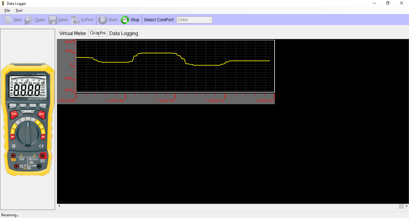
The meter makes a chart of the received values, the scale is just a generic 6000 scale and do not show I was using the 6.000V range.
I would also have like a larger chart.

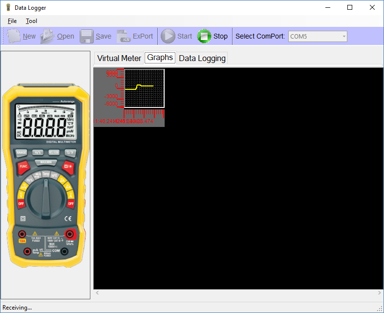
Going down to the smaller window did scale the chart, it do not make it easier to read.
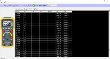
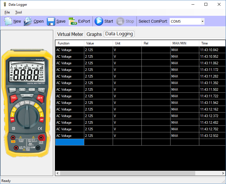
The meter saves each data point and they can be viewed in a table together with the time.
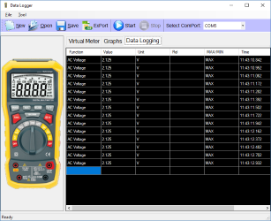
The max/min and REL columns do not show numbers, only that the function is activated.
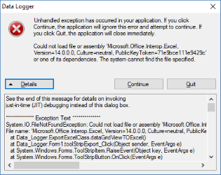
It is possible to save data or export data, the export function requires that Excel is installed, I did not have that.
With the save function it is possible to read data again and watch the table and chart.
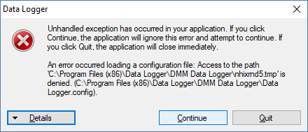
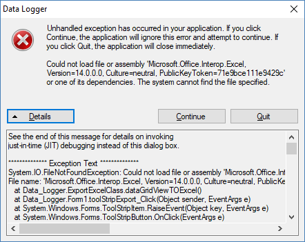
I also had another error when I closed the program.
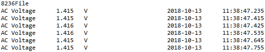
The data from the save function is a tab delimitered file and can be read by Excel.
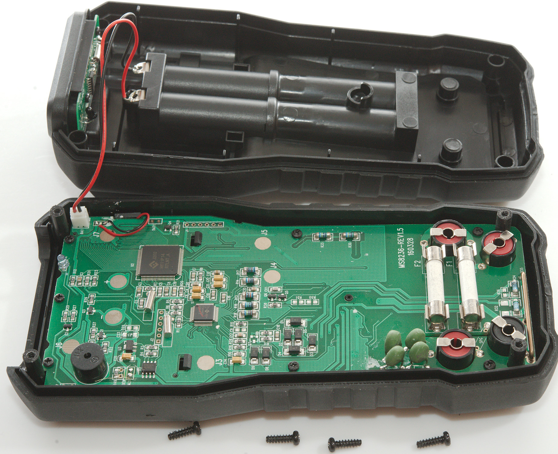
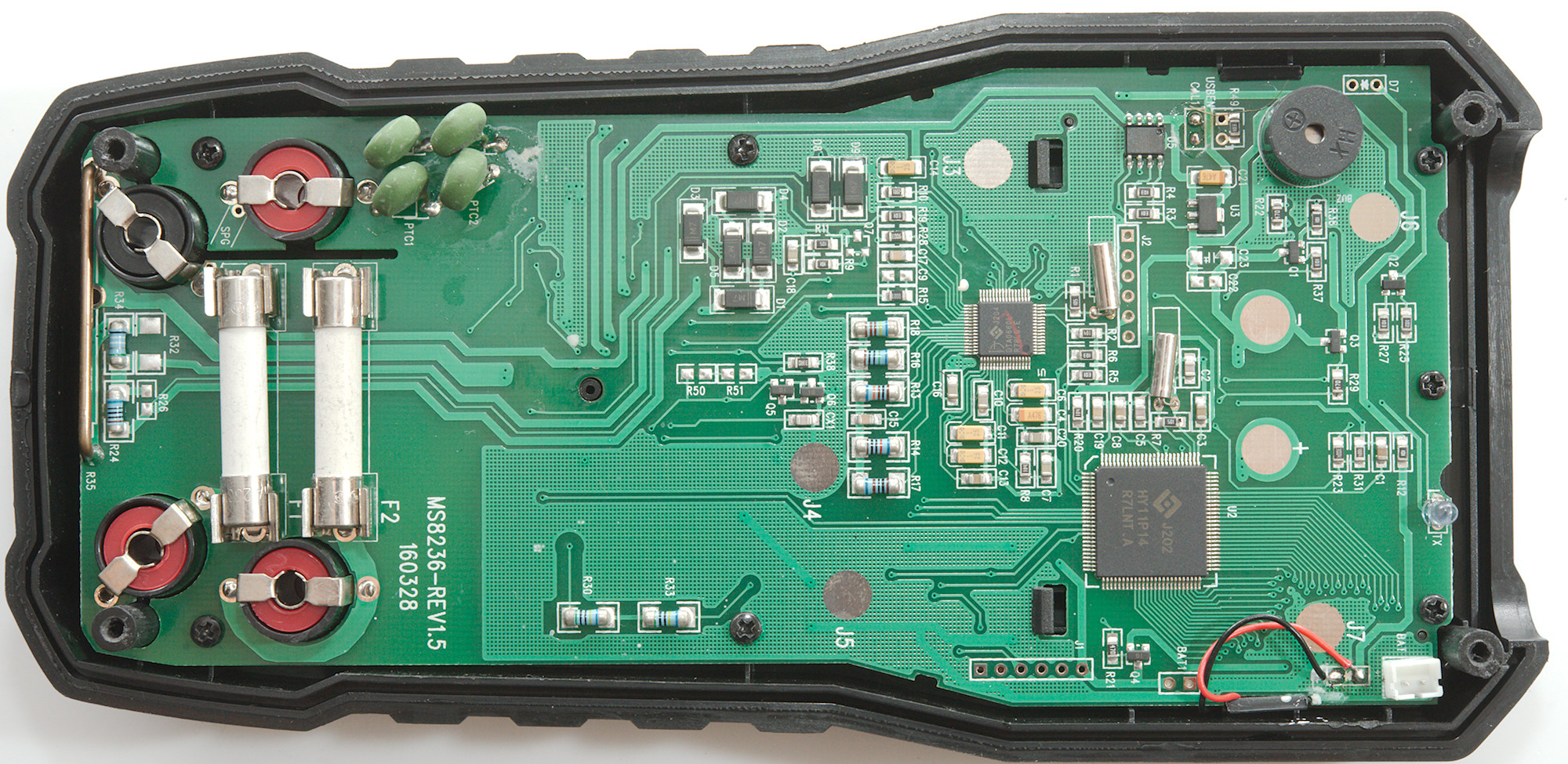
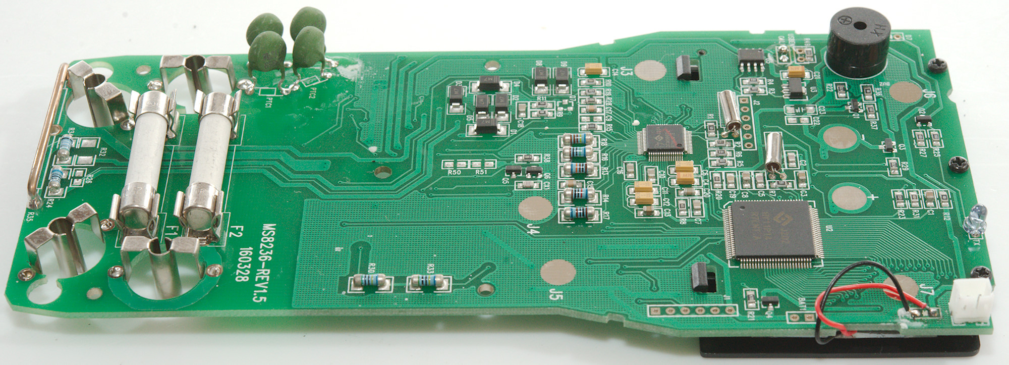
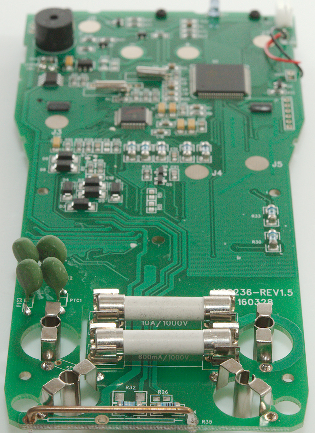
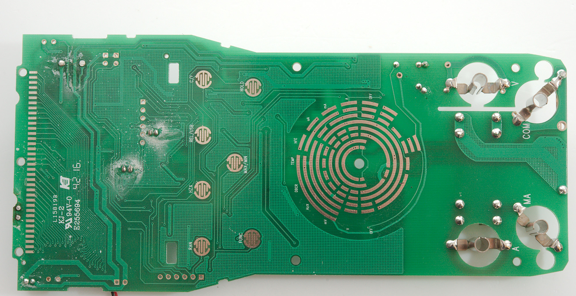
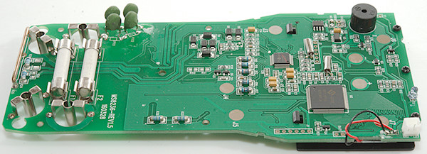
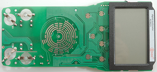
Tear down
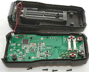
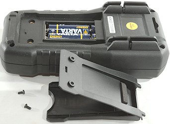
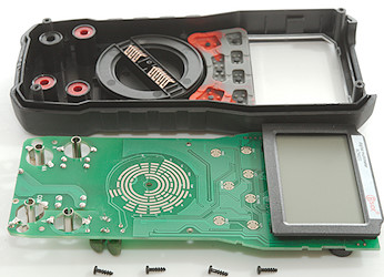
I had to remove four screws and I could open the meter.
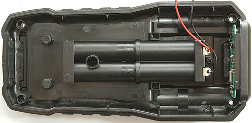
The circuit board are shaped to fit the meter.

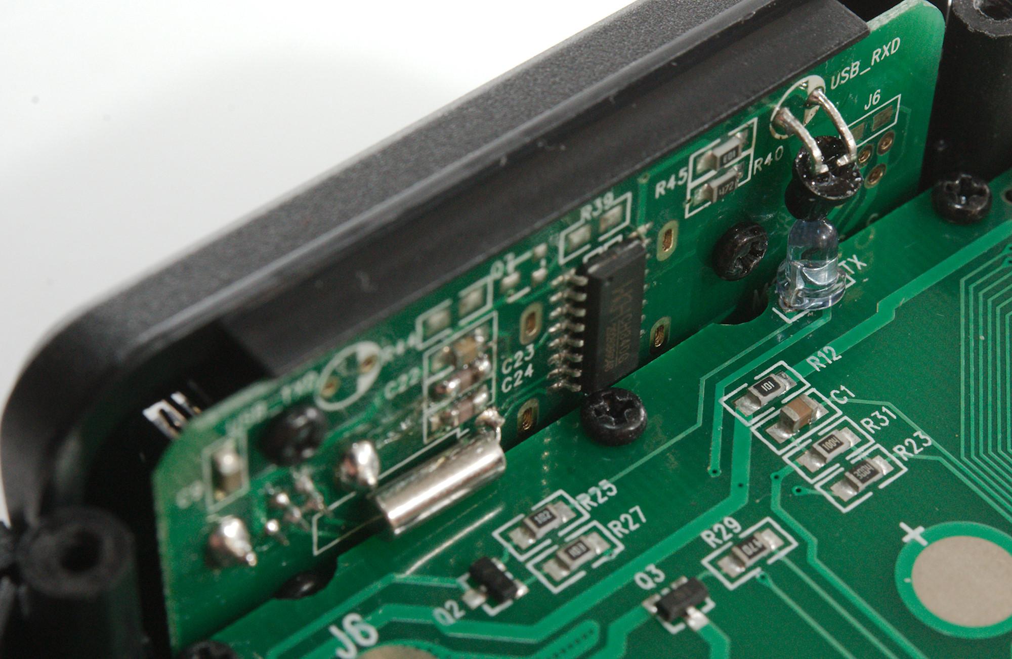
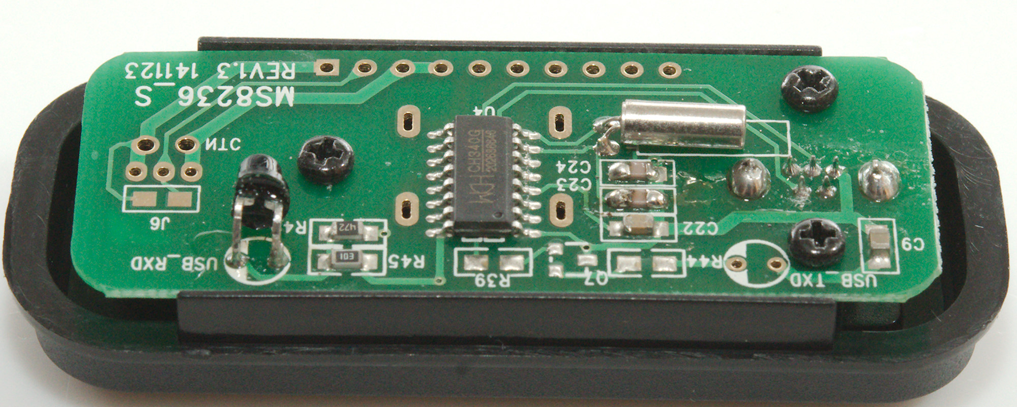
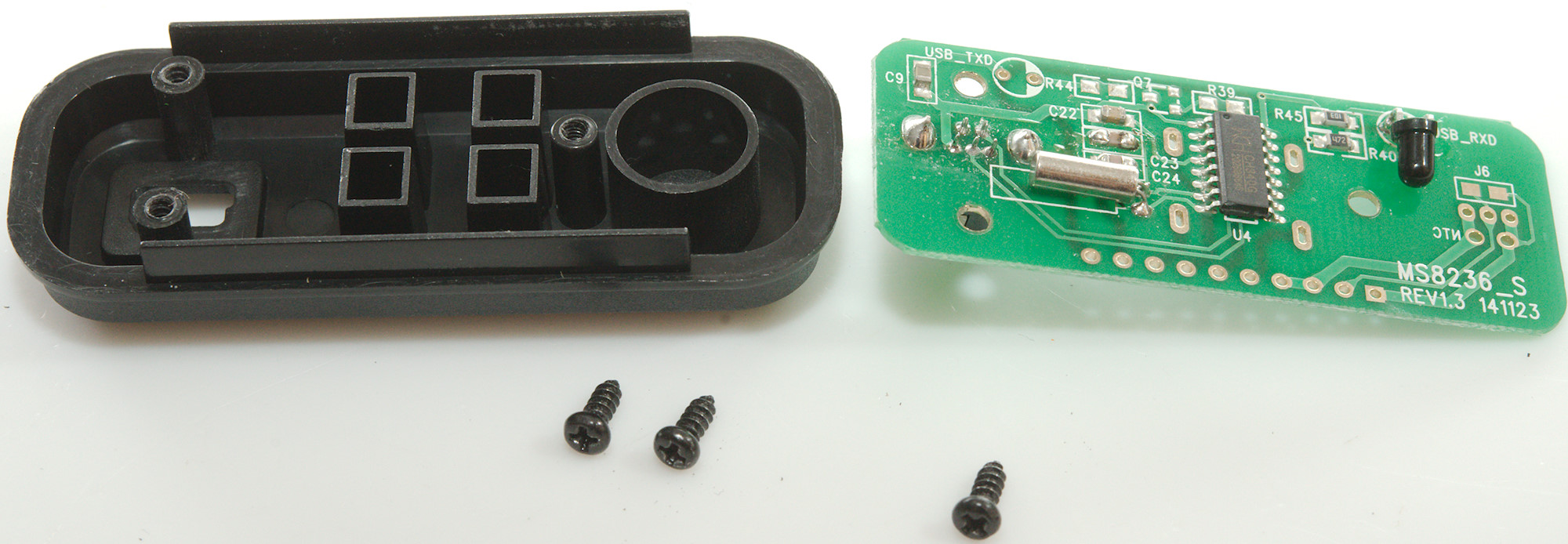
At the front is the usb interface and it is not connected to the meter circuit board. I will take a closer look at this later on.
The circuit board was mounted with four screws around the range switch.
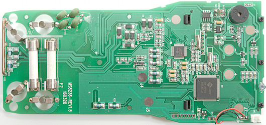
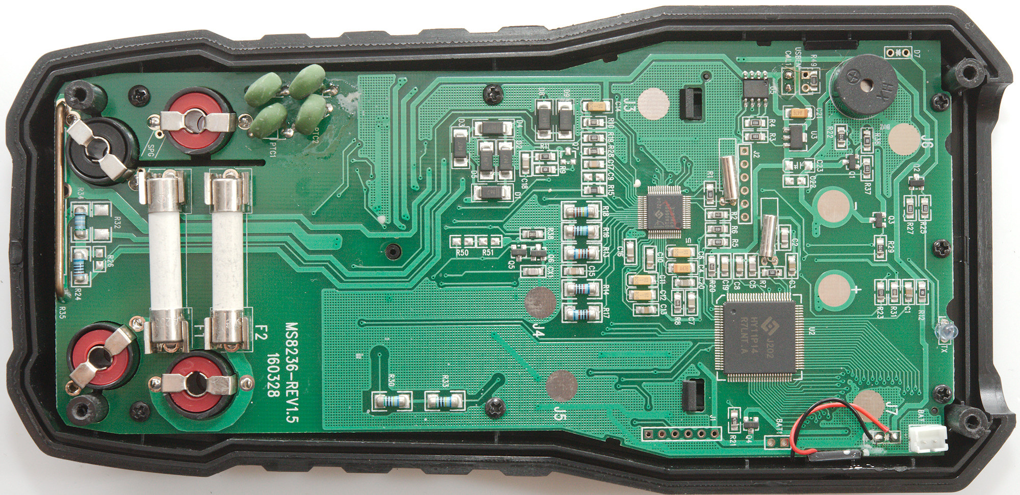
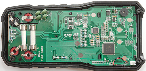
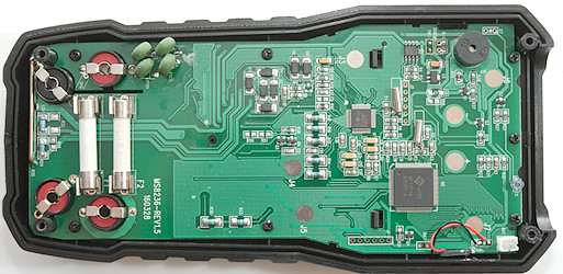
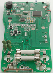
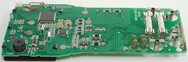
The current input uses some long fuses, but the mounted ones are only rated for 250V (oops). The mA resistor (R34: 1ohm) and uA resistor (R26 100ohm) are protected with a diode bridge (D1..D5).
The voltage input uses two paths each with two PTC's (PTC1 & PTC2, PTC3 & PTC4), the voltage input resistor (R30 & R33: 2x5Mohm) is the split in two. In mV, Hz, ohms, Temp the meter uses PTC1 6 PTC2 together with a transistor pair (Q5 & Q6) for input protection, but in ohm a secondary path is required, that uses PTC3 6 PTC4 and goes to a small SMD resistor (R28: 900kOhm) without further protection
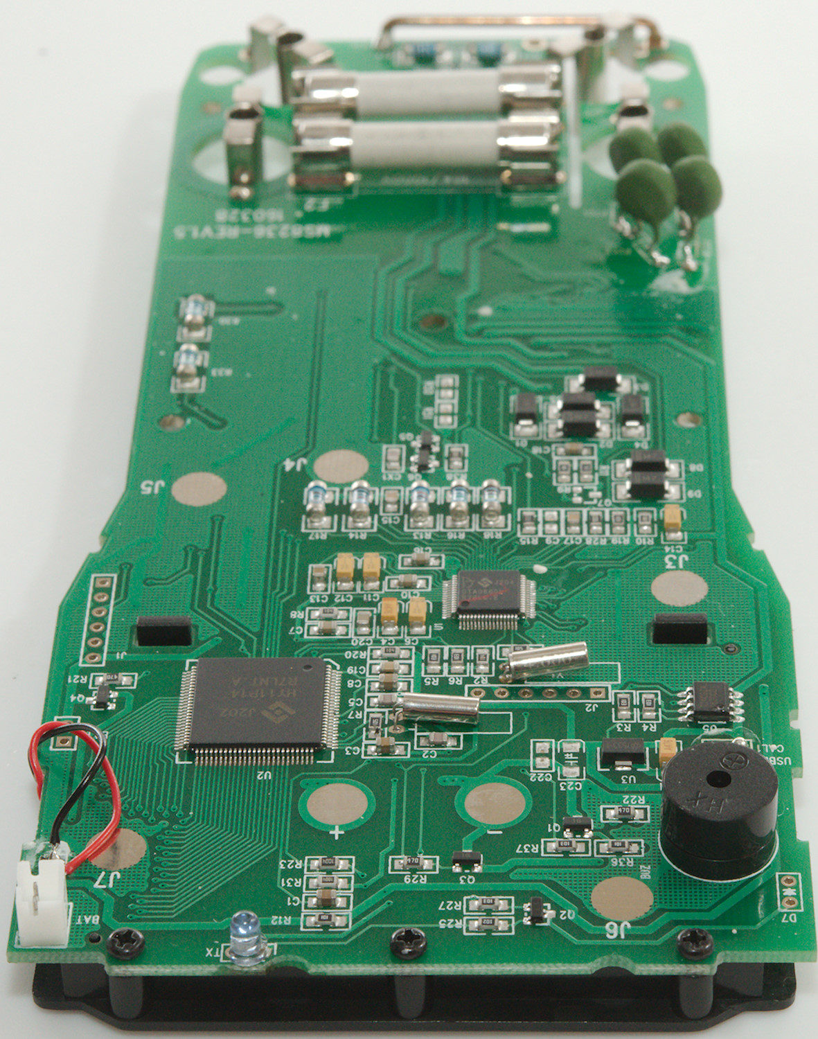
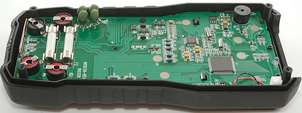
The multimeter part consist of two chips, a multimeter front end chip (U1: DTA0660L) and a processor, 18bit ADC and LCD driver (U2: HY11P14). There is also a EEPROM (U5: T24C02A) and a voltage regulator (U3: 7533-1: 3.3V).
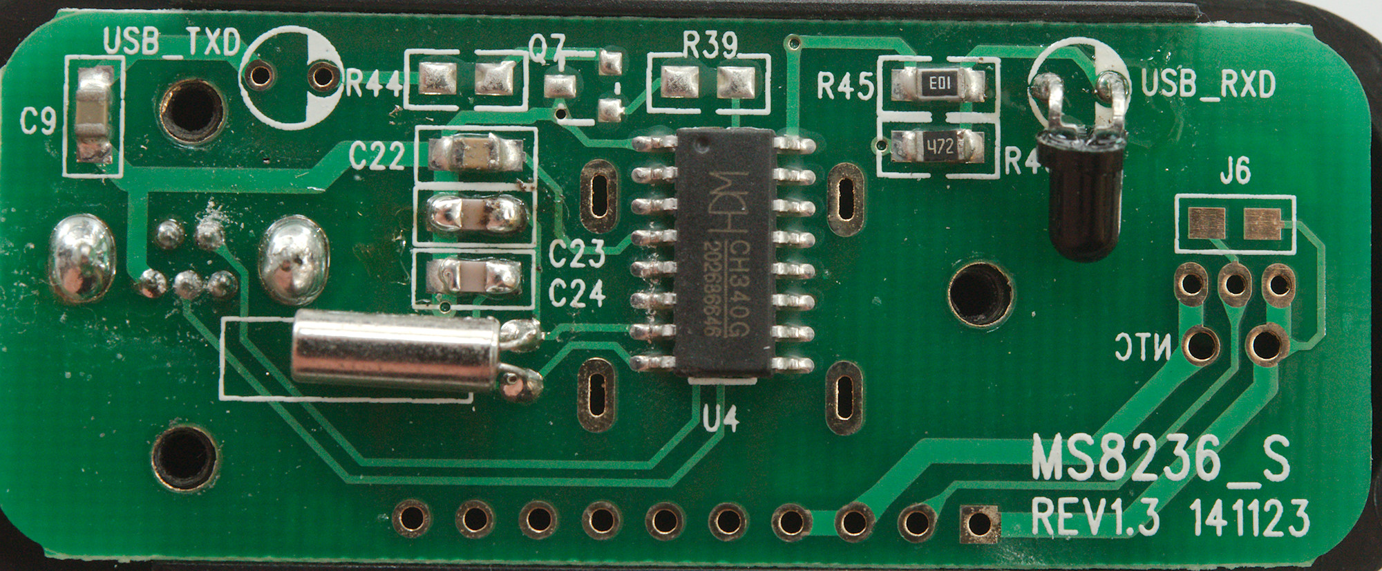
The USB interface is only a singled LED (TX) on this circuit board.
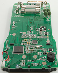
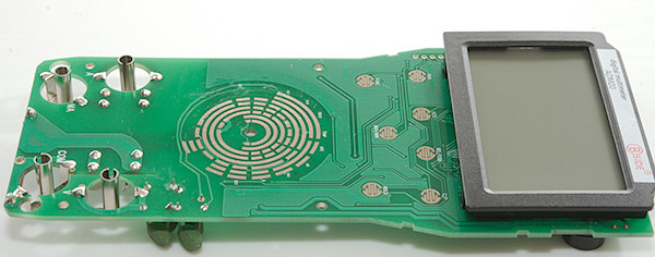
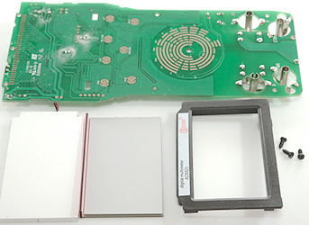
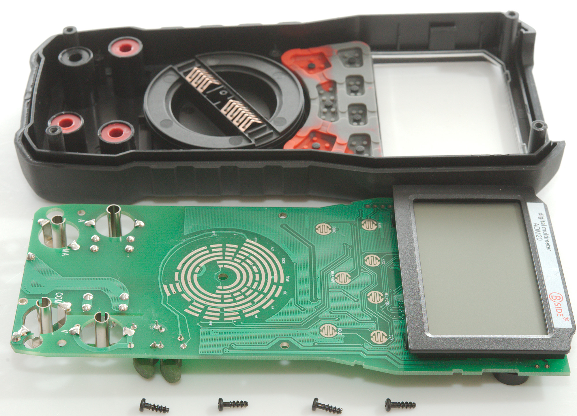
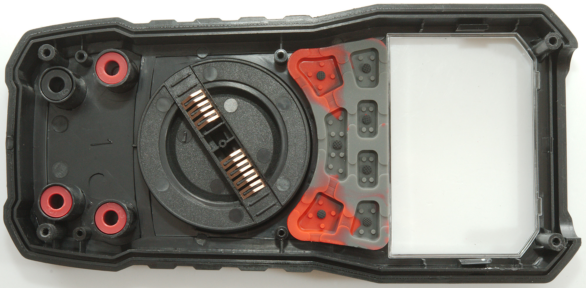
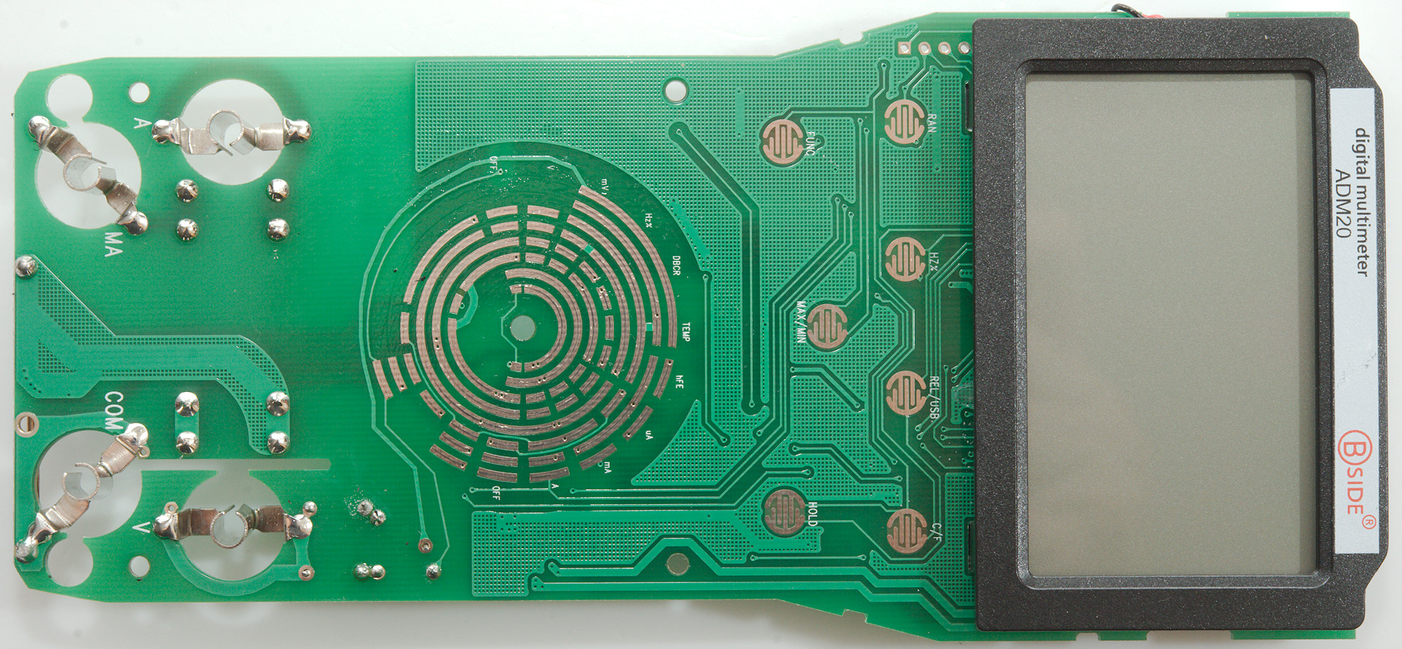
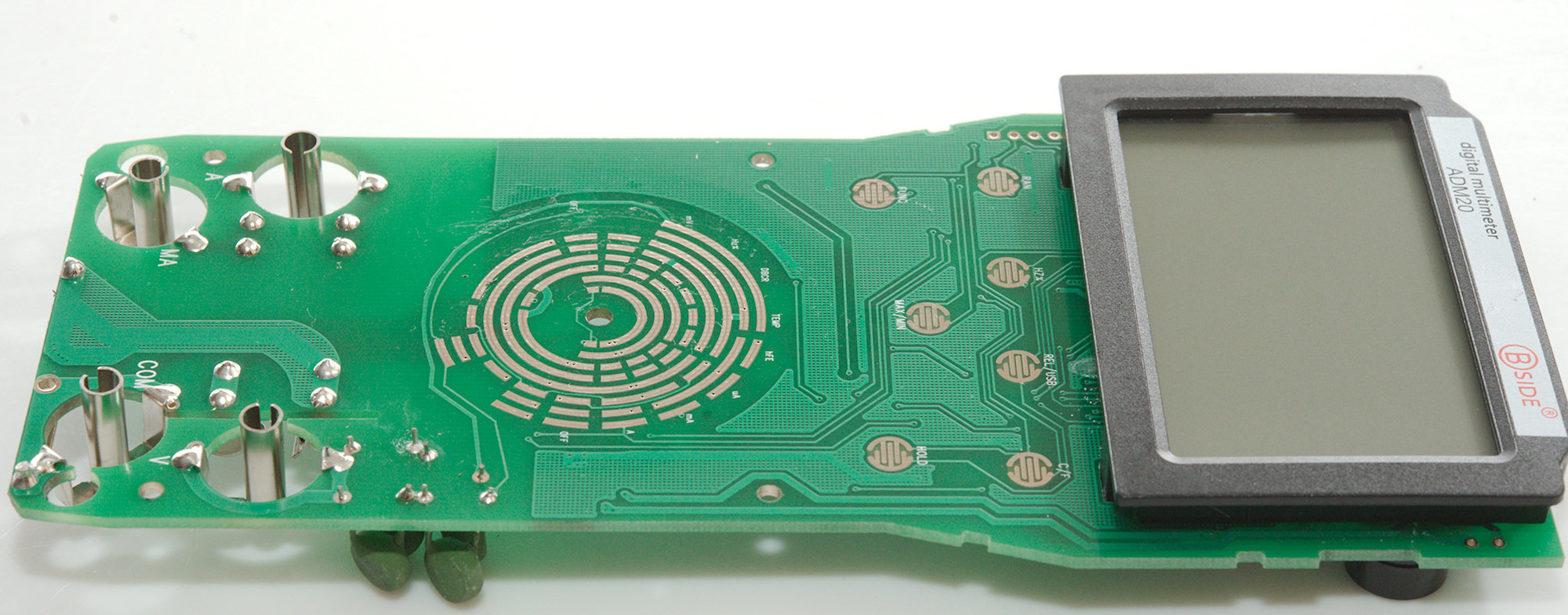
I had to remove 3 screws to remove the display and backlight.

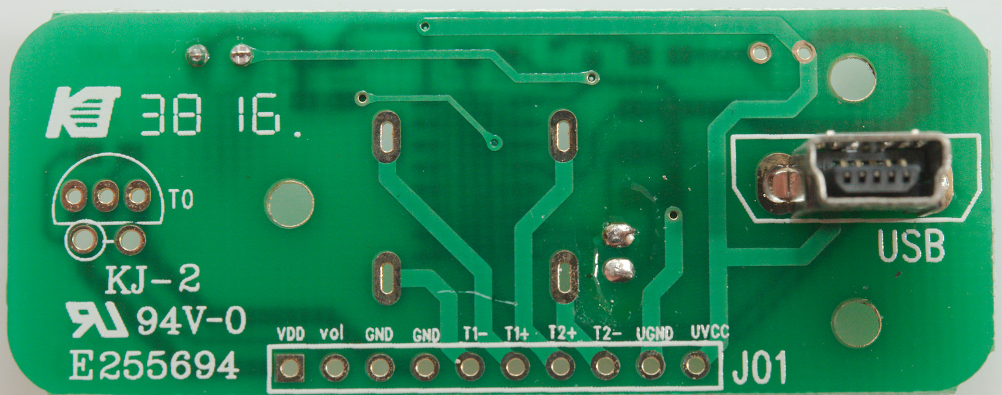
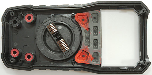
This side only has pads for the rotary switch, the buttons and the LCD display.


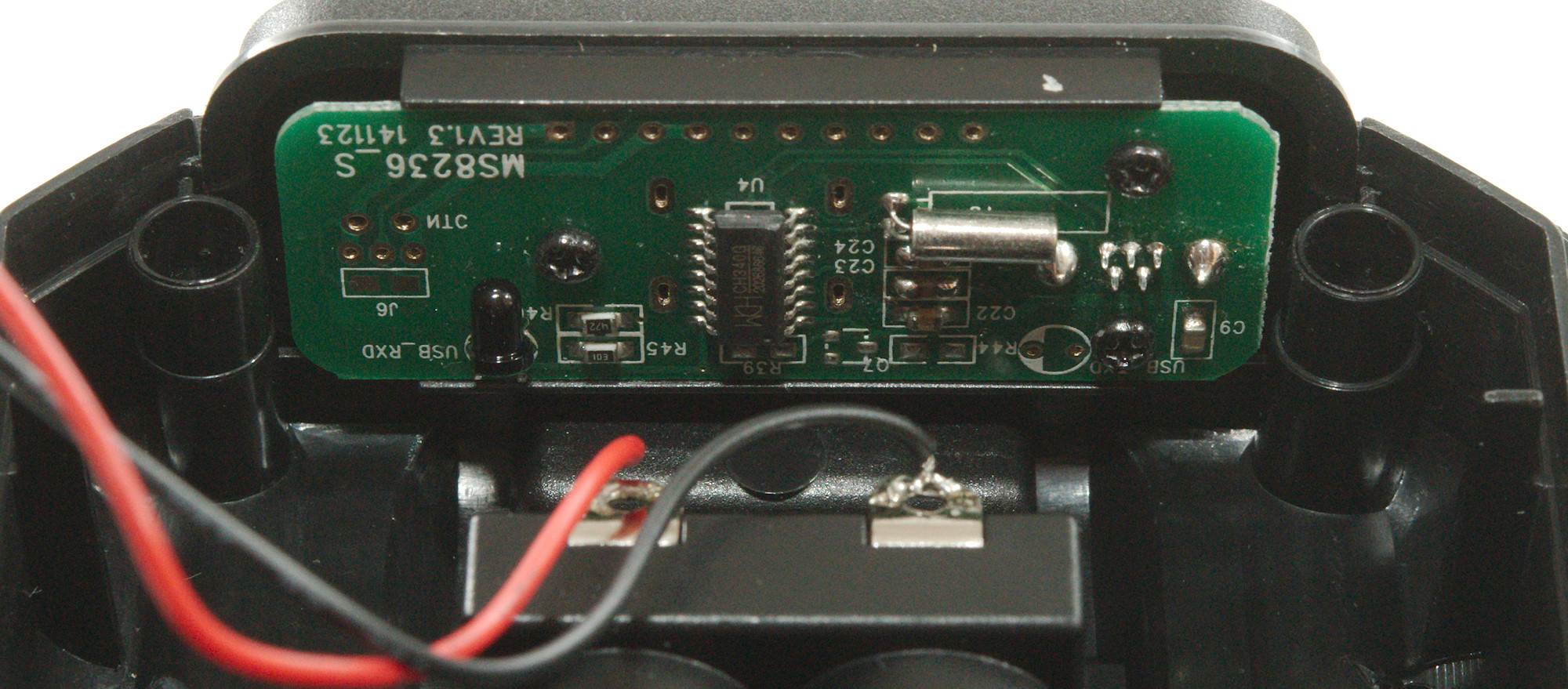
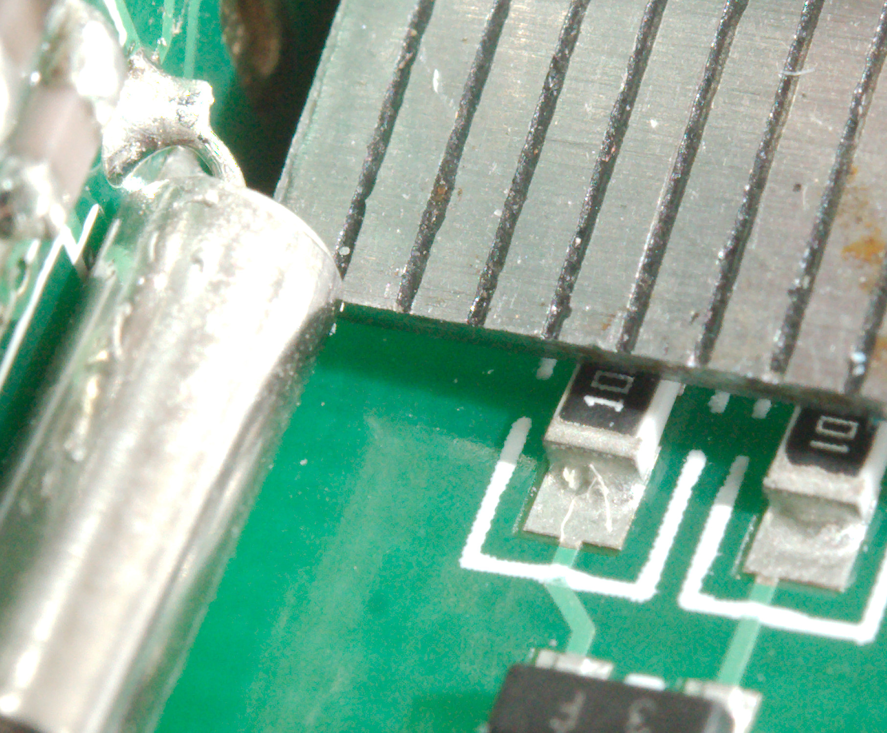
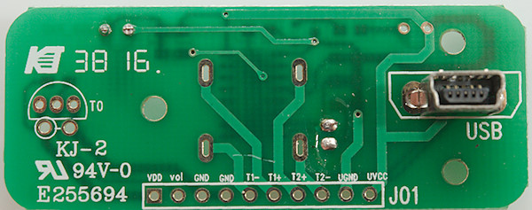
The USB interface is mounted at the front and is very close to the main circuit board, I would say too close, the crystal is only a few mm and it could move if the meter is dropped. The transmit and receive diodes are also very close together.

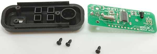
It is mounted with 3 screws, two close to the USB interface securing it against pressure when pushing the USB connector in.
It looks like this piece of plastic and the circuit board can be used for more functions, maybe thermocouplers, but then the isolation distance will be very low.
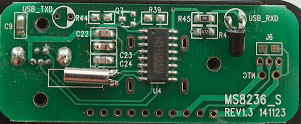
The USB interface is a standard serial interface chip (U4: CH340G).
Conclusion
At first glance the safety looks good, but there are a couple of caveats: The mounted fuse is only 250V, the voltage input has fairly low distance to common and do not use MOVs. In the ohm range a small SMD resistor must handle full input voltage (After the PTC). The USB interface is isolated, but isolation distance is a bit low. This means the CAT rating is not valid.
The meter has all the common ranges and most common functions (max/min could be better) and it also has USB output, but I am not very impressed by the supplied software. If some other software can be found for the meter it may be a nice meter for logging on the bench.
Notes
How do I review a DMM
More DMM reviews