DMM BTMeter BT-39C
This meter is from BTMeter and is the 39C mode, this looks to be the most advanced multimeter in the 39 series.
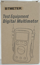
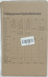
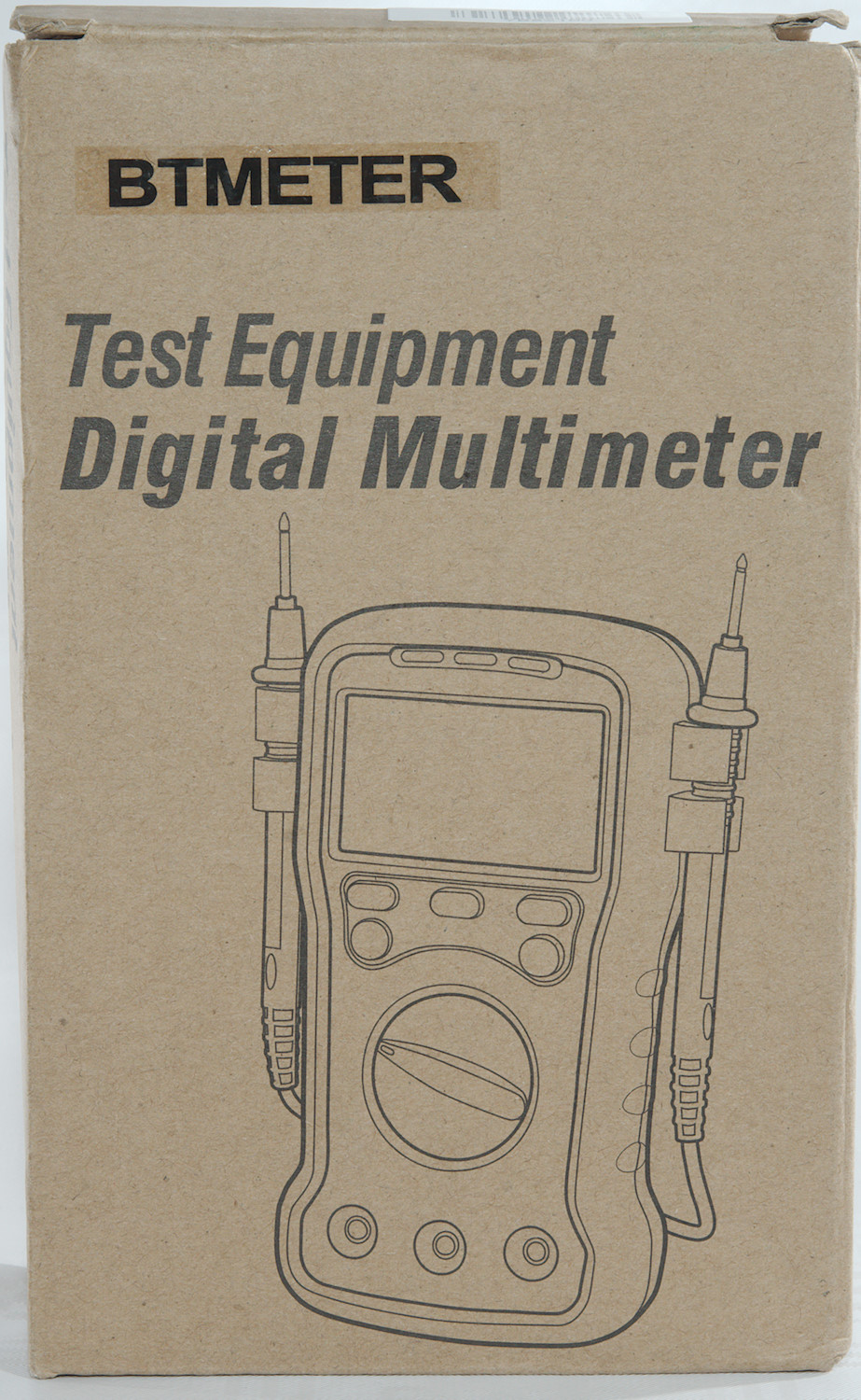
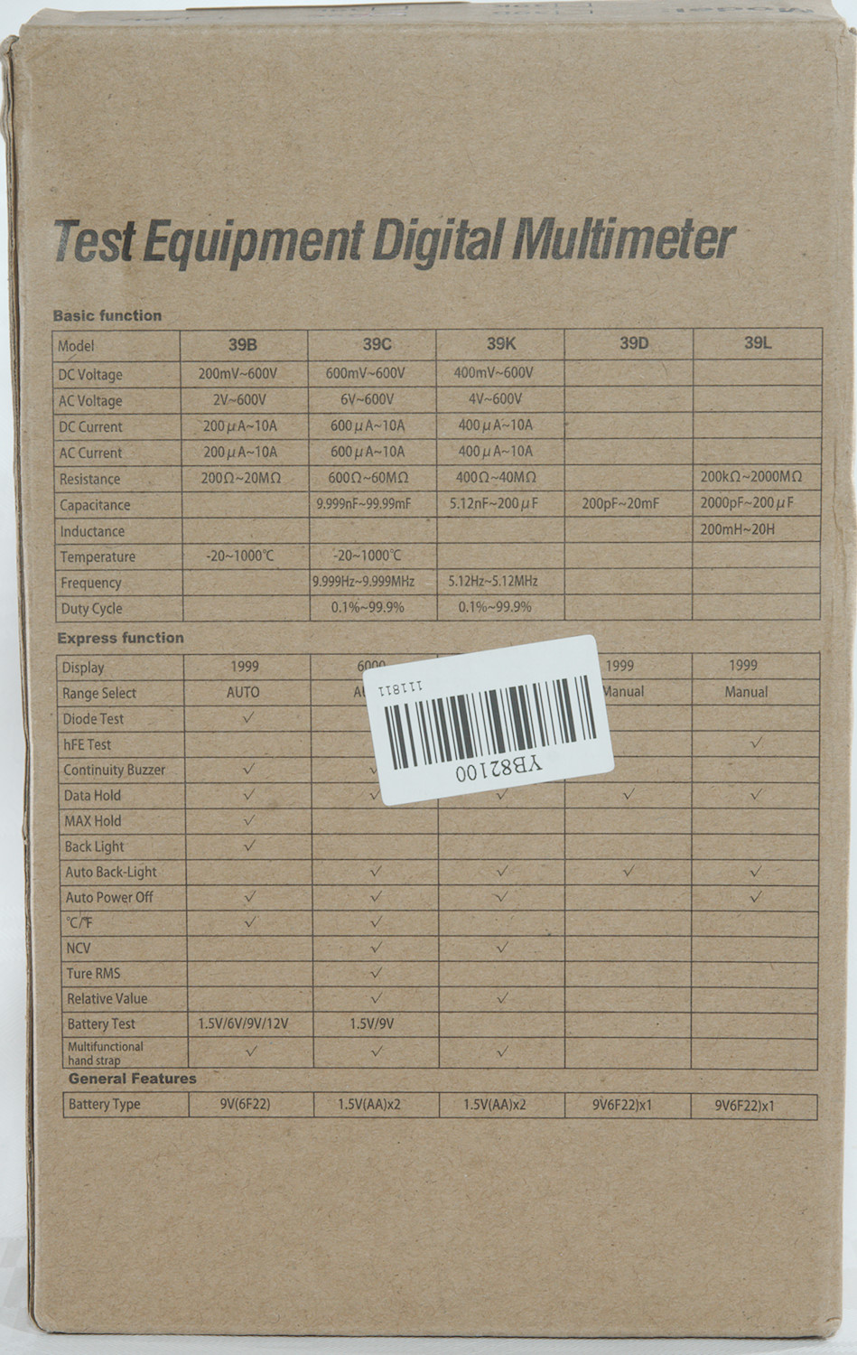
The meter arrived in a cardboard box, the branding is a label that is stuck on and on the back is a overview of the 39 series meters, including a capacitance and a LCR meter.
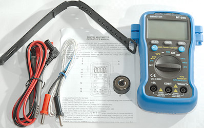
The box contained the meter, probes, thermocoupler, magnet, strap and a instruction sheet.
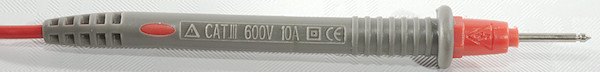
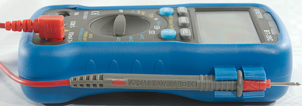
Probes are not branded and are specified for CAT III, this cannot be true with that much tip exposed.
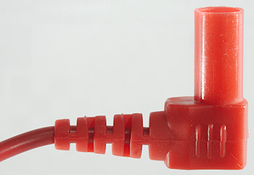
The plug is fully shrouded but a bit short.
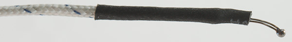
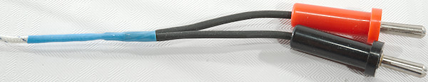
A standard cheap thermocoupler with two banana plugs.
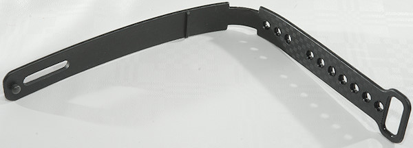
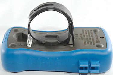
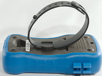
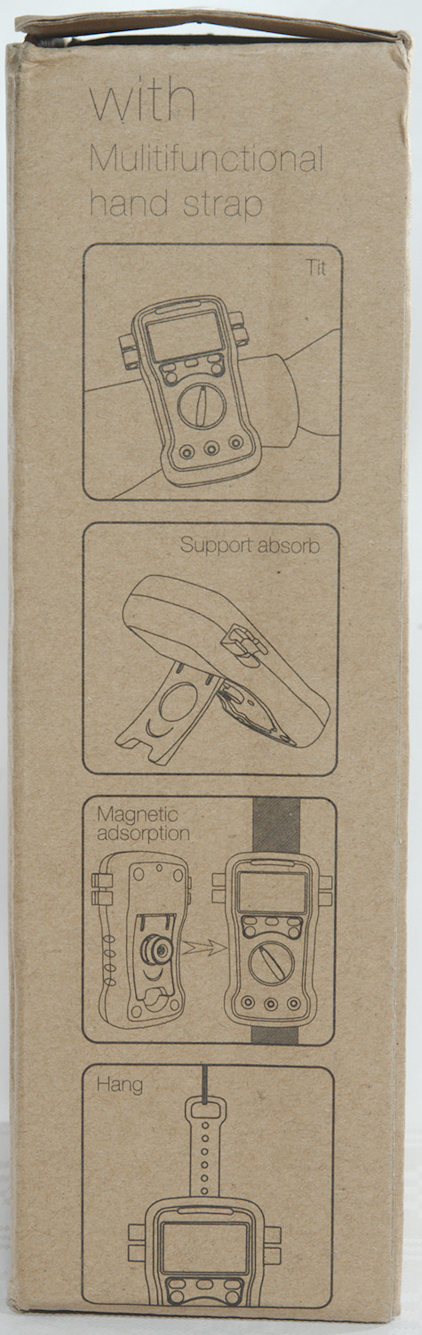
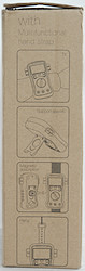
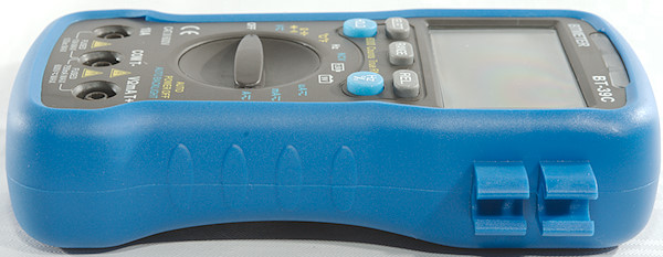
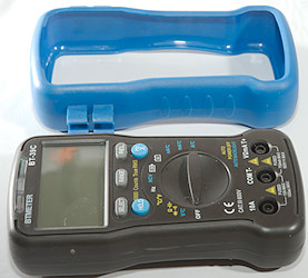
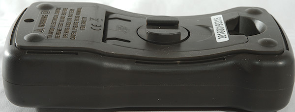
The meter includes a strap, it can be used as a hanger, but can also make a look behind the meter, probably to strap it to an arm.
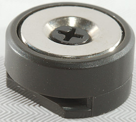
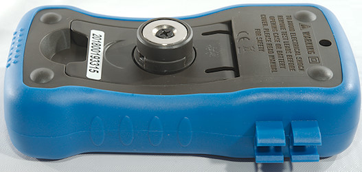
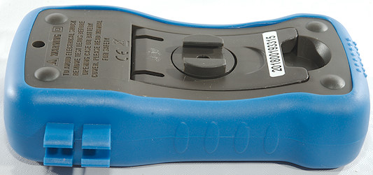
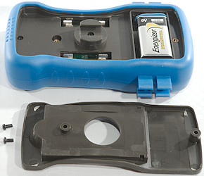
The magnet can be mounted on the back of the meter and used to secure it to metal.
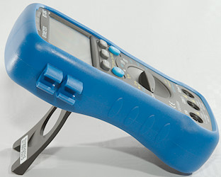
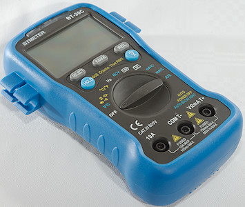
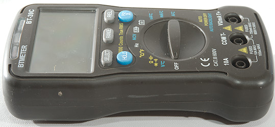
The rotary switch and button can be used single handed when using the tilting bale.

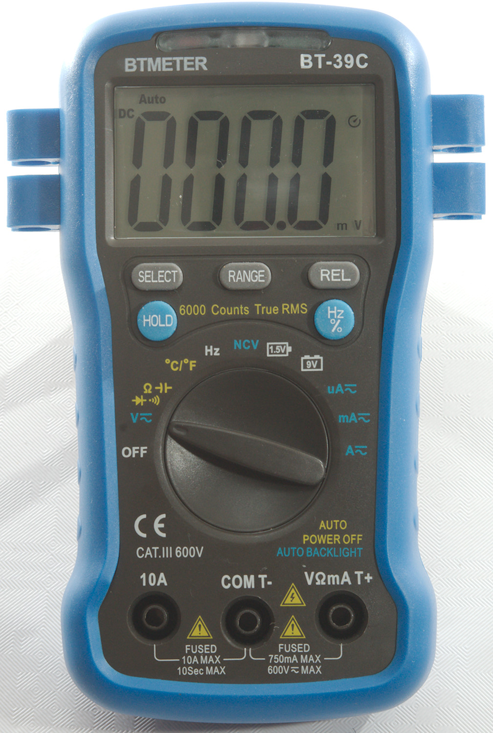
Display
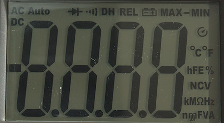
The above picture shows all the segments on the display, a few of them are not used.
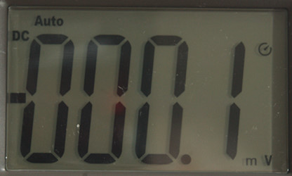
Usually the meter shows the selected range and the value.
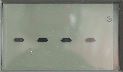
Non contact voltage uses bars to show the electric field strength.
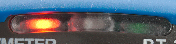
Add also a green and red led.
Functions
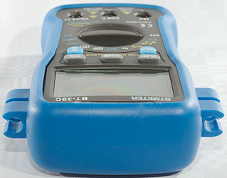
Buttons (Range selection and a few other are remembered):
- Select: Select AC/DC, ohm/continuity/diode/capacitance and Celsius/Fahrenheit
- Range: Switch to manual range and select range, hold down to activate automatic ranging again.
- Rel: Remember current value and show further values relative to this, press again to disable.
- Hold (Blue): Freeze the display, press again to release.
- Hz %: Select frequency in VAC and AAC modes, will also change between frequency and duty cycle.
REL will disable auto ranging.
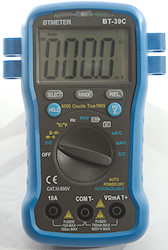
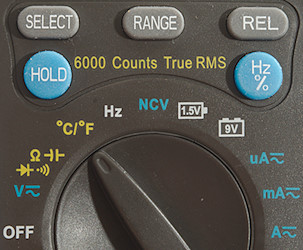
Rotary switch:
- Off: Meter is turned off.
- V: Measure DC and AC voltage, use Hz button for frequency and duty cycle, mVAC can only be selected with RANGE button.
 : Resistance, continuity, diode and capacitance.
- °C/°F: Measure temperature with a thermocoupler, will display meter temperature when no thermocoupler is connected.
- Hz%: Logical frequency and duty cycle, this has much higher bandwidth.
- NCV: Non contact voltage or electric field detection.
 : Measure 1.5V battery with load
 : Measure 9V battery with load
- uA: The uA range, use Hz button for frequency and duty cycle.
- mA: The mA range, use Hz button for frequency and duty cycle.
- A: The A range, , use Hz button for frequency and duty cycle.
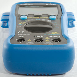
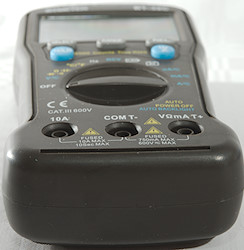
Input
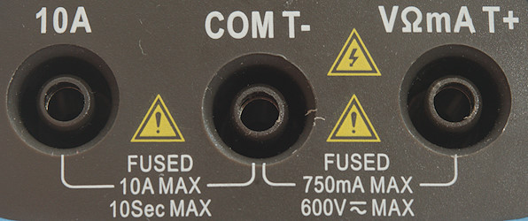
- A: High current, maximum current is 10A
- COM: The common terminal for all ranges.
- xxx: All other ranges.
Measurements
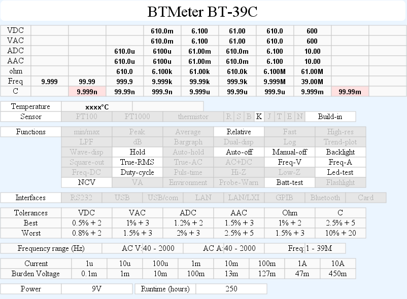
- Volt and frequency
- At 0.1Vrms frequency input (VAC) range is from 0.7Hz to 4kHz
- At 1Vrms frequency input (VAC) range is from 0.5Hz to 15MHz
- Frequency input (VAC) requires a zero crossing.
- At 0.1Vrms logical frequency input (Hz) range is from 0.7Hz to 8MHz
- At 1Vrms logical frequency input (Hz) range is from 0.5Hz to 39MHz
- Logical frequency input (Hz) requires a zero crossing.
- Duty cycle works from 1% to 99% at 100kHz with 1Vpp, precision is within 0.1
- 1 VAC is 5% down at 2.4kHz (RMS will not work at the frequency).
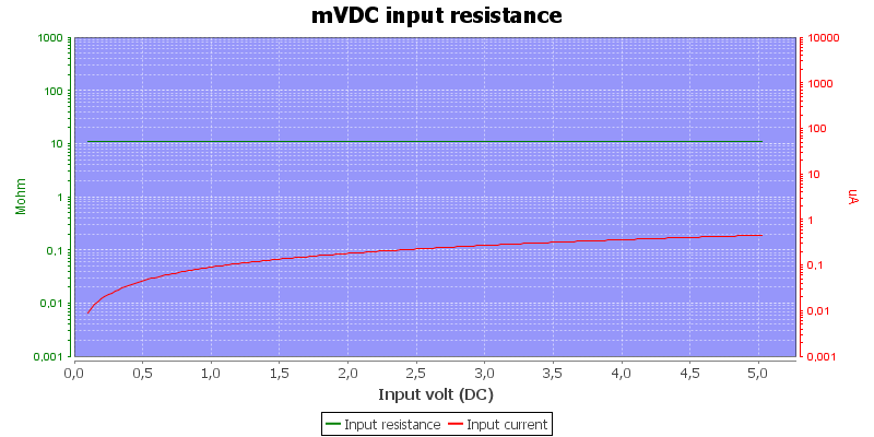
- Input impedance is 10-11Mohm on mVDC/mVAC/DC/AC
- Frequency input has high input impedance up to about 1.5V then drops to about 2kOhm
- 1.5V battery test uses a 30ohm resistor, i.e. the load is 50mA at 1.5V
- 9V battery test uses a 910ohm resistor, i.e. the load is 10mA at 9V
- Rated overload protection on V ranges 600VDC or VAC
- Meter has audible alarm on over voltage.
- Current
- Overload protection in uA and mA: 0.75A/250V 6x30mm fuse
- Overload protection in A: 10A/250V 6x30mm fuse
- Ohm, continuity, diode and capacitance
- Ohm needs about 2.7s to measure 100ohm
- Ohm is 1.1V open and 0.26mA shorted
- Continuity is fast (15ms).
- Continuity beeps when resistance is below 50ohm
- Continuity is 2.1V open and 0.26mA shorted
- Diode range uses 4.0V, max. display is 3.3V at 0.27mA, max. current is 1.6mA shorted
- 10uF takes about 2.3 seconds to measure.
- 11000uF takes about 9.5 seconds to measure.
- Rated overload protection on ranges 600 VDC or VAC
- Miscellaneous
- Current consumption of meter is 1.3mA-1.8mA in most modes, NCV uses 7.6mA due to the led (7.3mA with backlight fully on).
- Meter works down to 1.4V, where it turns off, battery symbol show at 7.3V.
- The meter reading is stable down to about 1.8V, then it will show a random value.
- Backlight is stable down to 5.2V then it start to fade and is just about off at 2.6V
- The meter will usual show correct value in first display update
- Viewing angle is good except from top
- Display updates around 3 times/sec
- Backlight display is directly controlled by a LDR and will turn slowly on when it gets darker (Backlight is disabled in NCV mode).
- Will automatic turn power off in about 16 minutes
- Standard probes cannot be pushed fully down.
- Weight is 259g without accessories, but with batteries.
- Size is 151 x 100 x 37mm.
- Probes
- Probe resistance about 60mOhm for one.
- Probe wire is on the thin side, not soft and 65cm long.
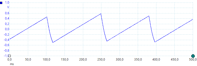
A look at the capacitance measurement waveform when measuring 1uF
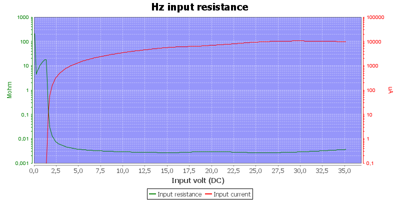
Frequency input resistance, the impedance is very high with low input signals.
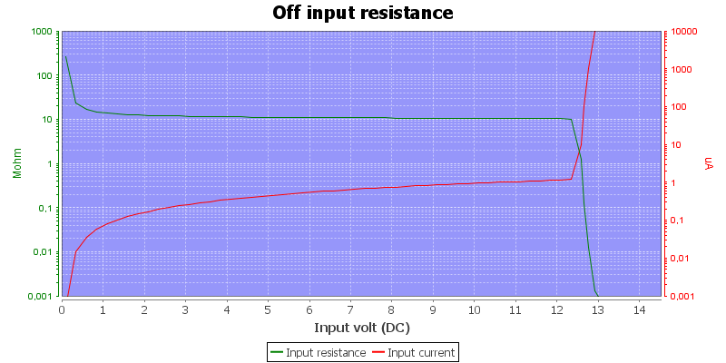
Oops, I do not like this off resistance, it is below 1kOhm above 13V, this means it goes around the PTC's at the input. Something is probably going to blow when measuring higher voltages with meter in off. During the tear-down I traced this: The input goes through the 0.75A fuse and the zener diodes.
Lowest capacitance range has more than 20pF negative offset when measuring 100pF.
Highest capacity range cannot measure my 70000uF capacitor.
Large DC values may prevent the meter from showing AC values.
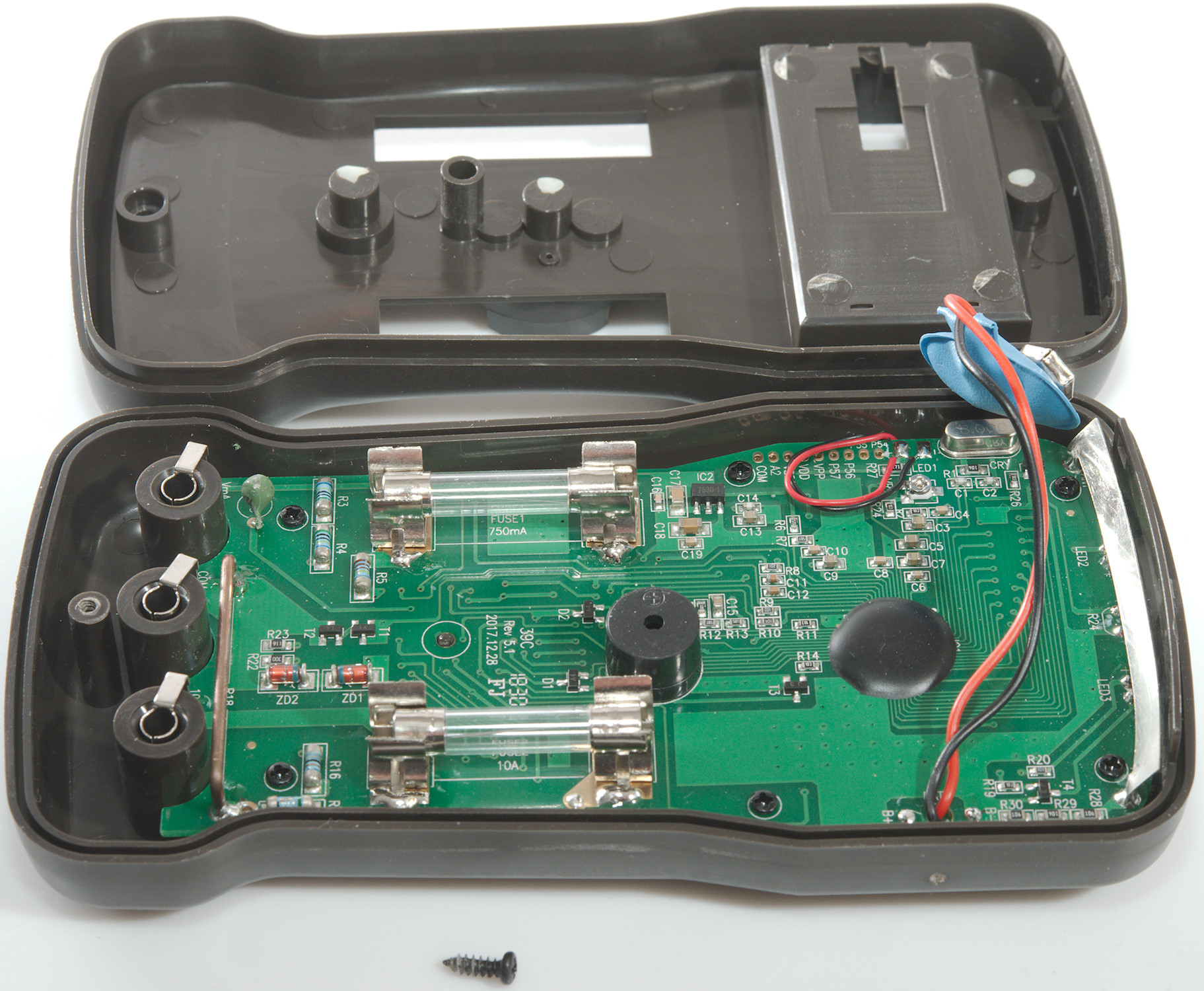
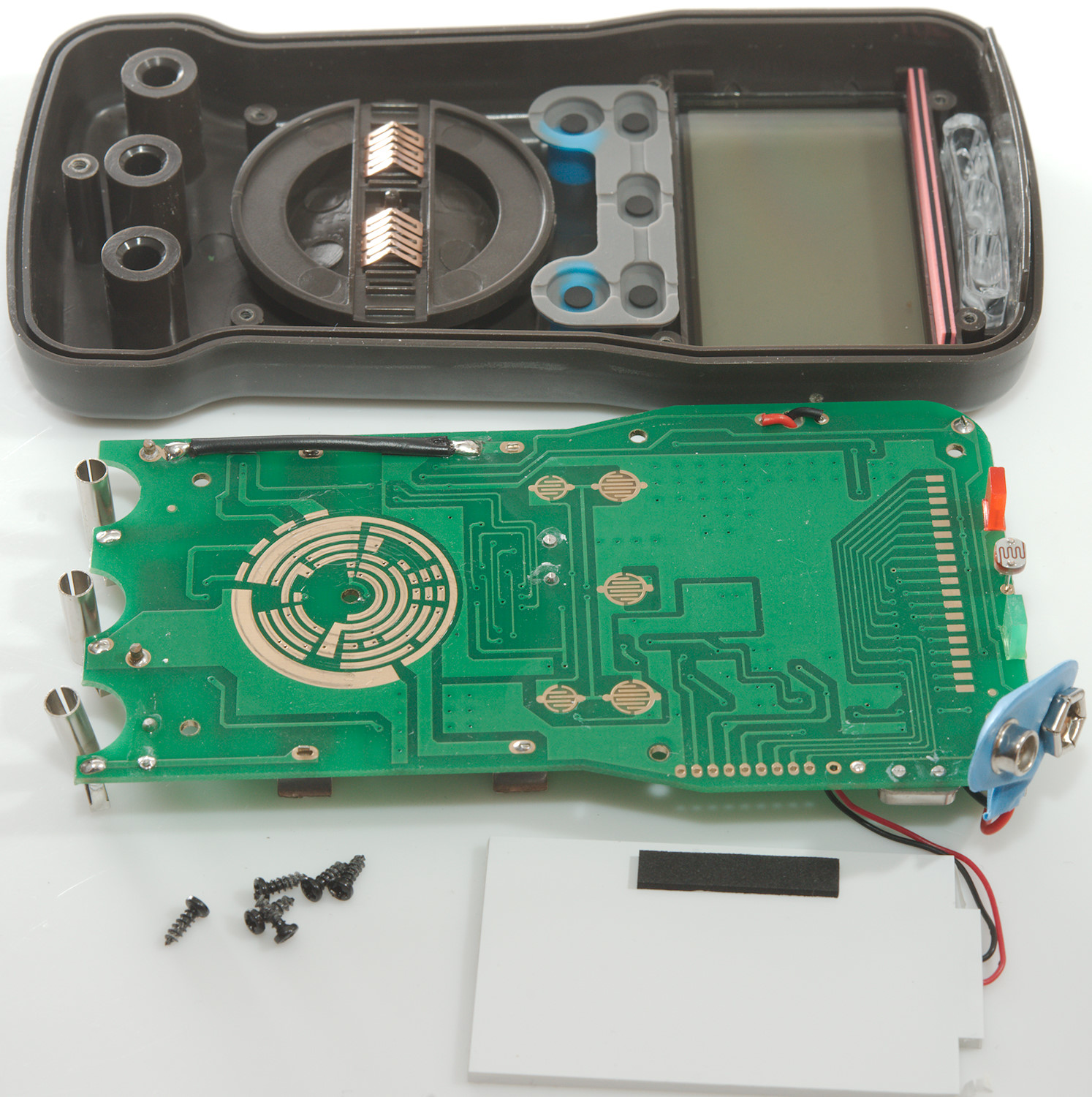
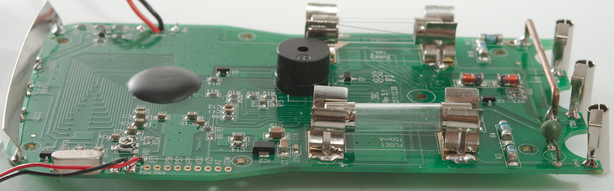
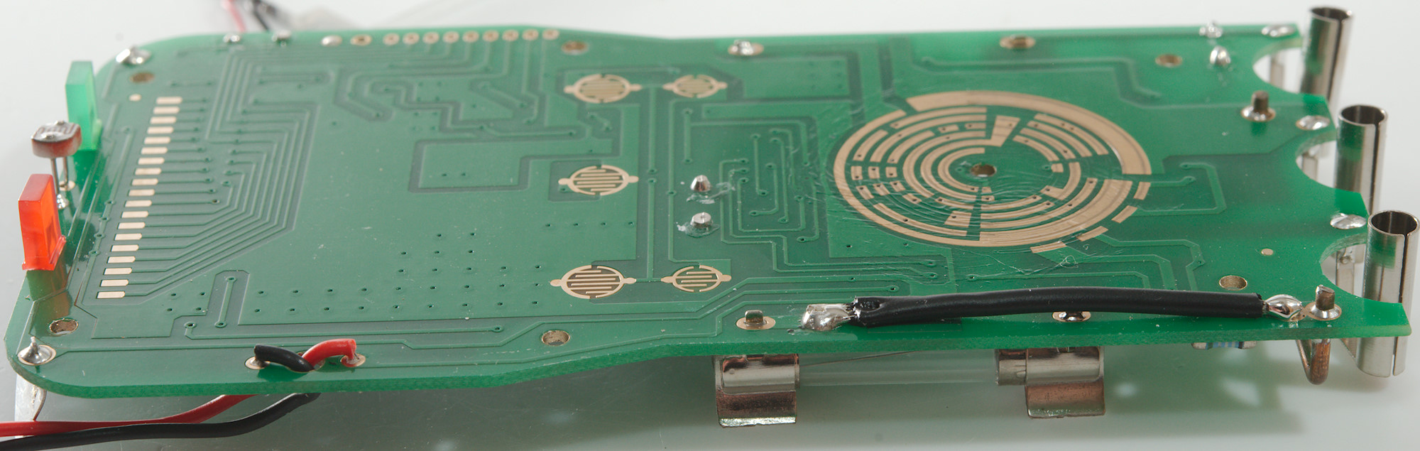
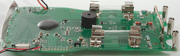
Tear down
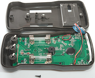
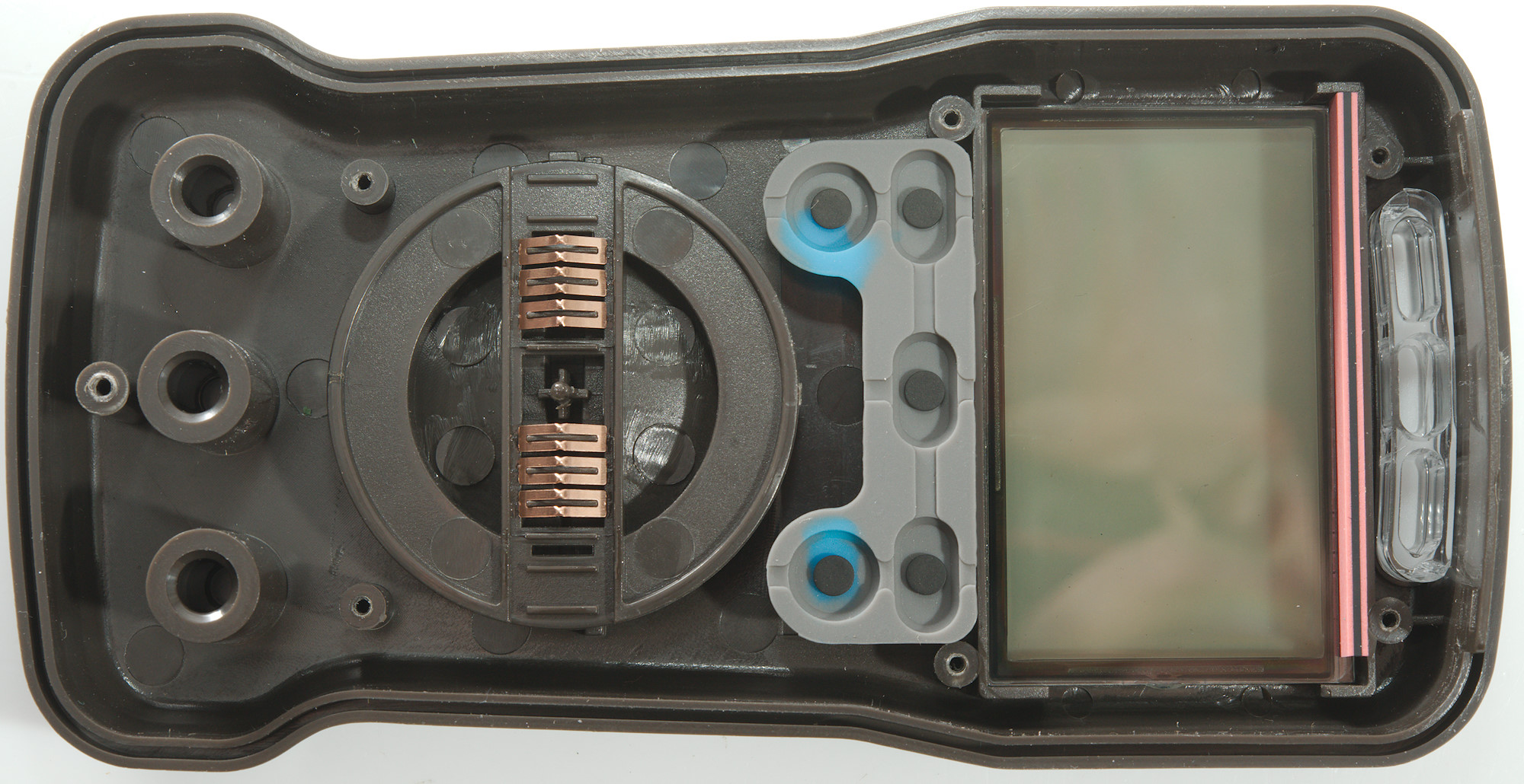
After removing the battery cover I only had to remove one screw to open the meter.

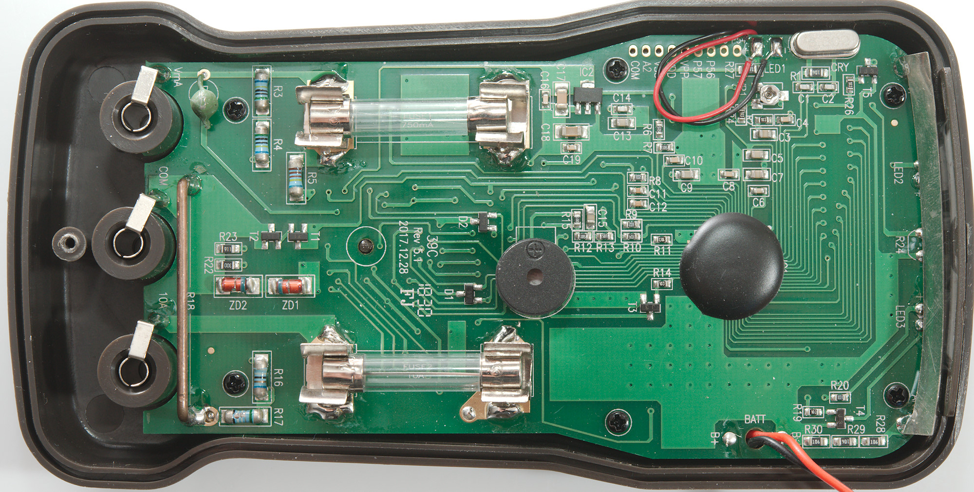
The circuit board was mounted with six small screws.
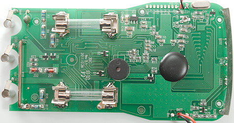
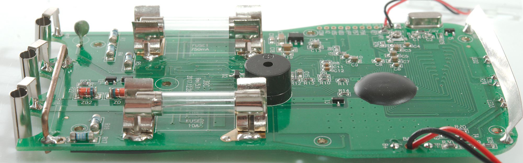
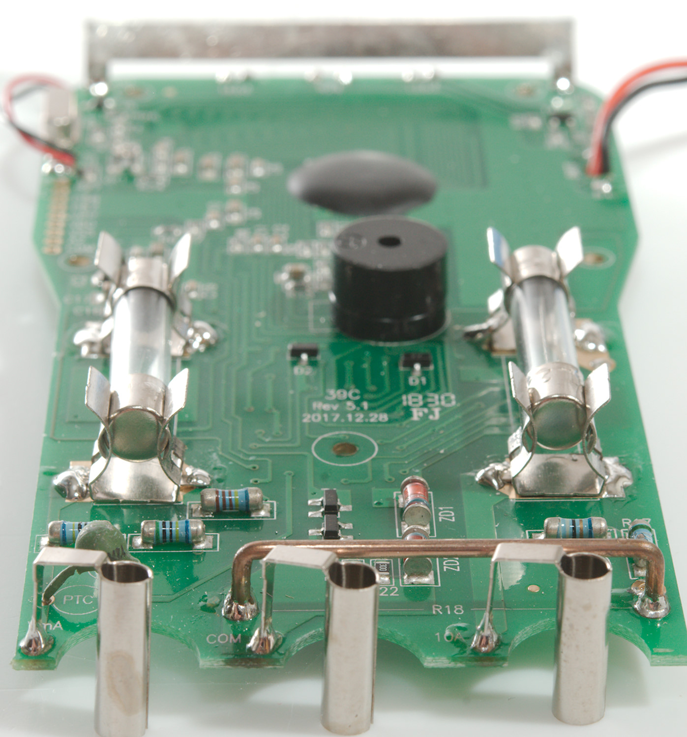
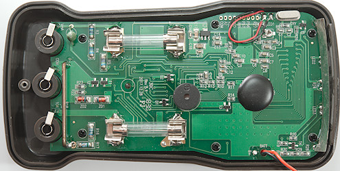
The 10A range was a fairly large shunt (R18) and a long fuse. The two resistors at the end of this shunt are the mA (R17: 1ohm) and uA (R16: 99ohm) shunts. There are also resistor for the 1.5V battery range (R22: 30ohm) and 9V range (R23: 910ohm), these ranges also uses the 0.75A fuse, but the small SMD resistor will not survive 0.75A. All these ranges (Except 10A) are protected by two zener diodes (ZD1 & ZD2: 12V) in reverse series. For voltage input there is a 10Mohm resistor (R3 & R4: 2x5Mohm).
Ohm ranges probably measures through another resistor (R5: 1.1Mohm) and supply current through the PTC and a transistor pair (T1 & T2), this transistor pair is also used for temperature and frequency.
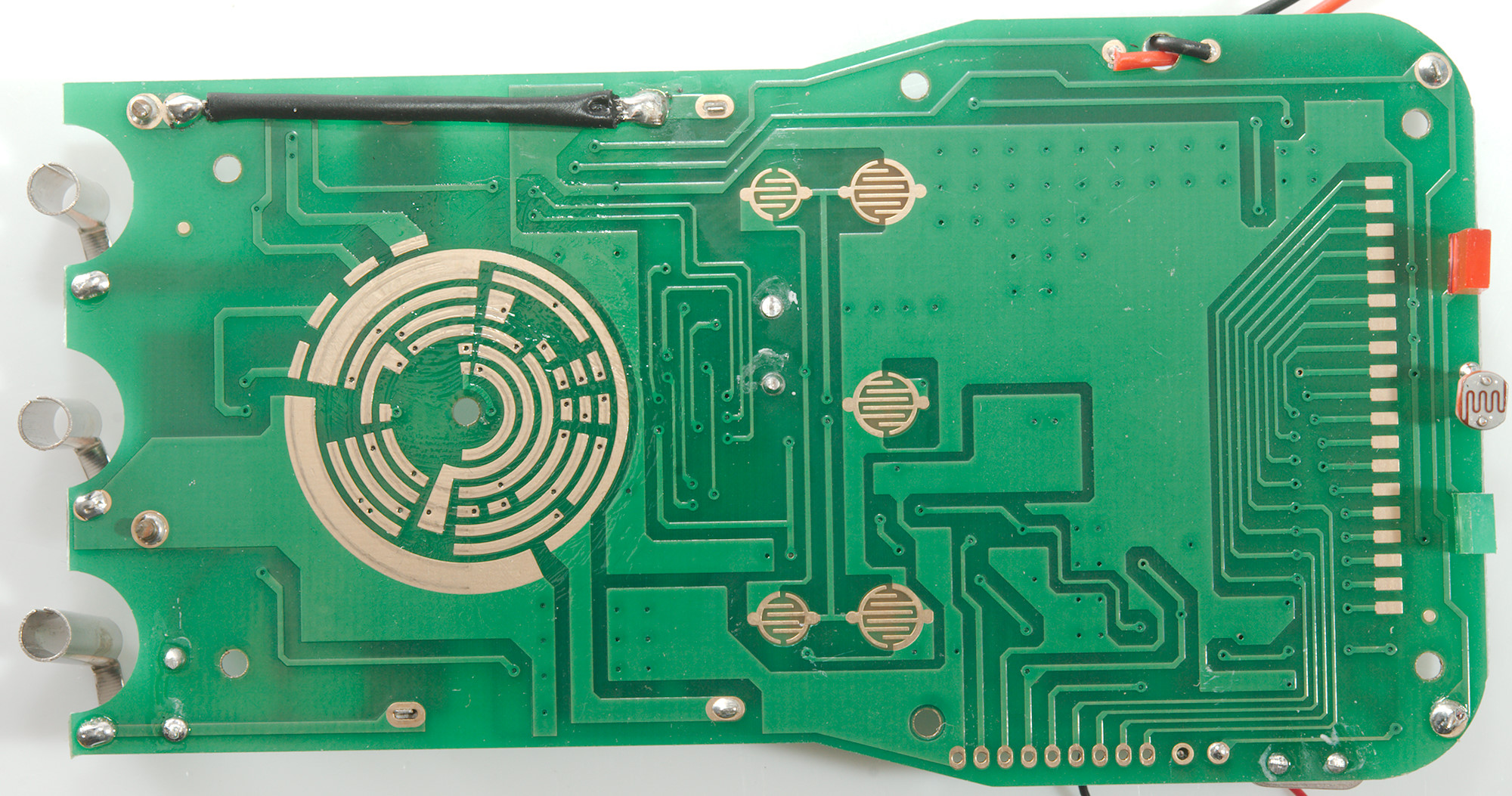
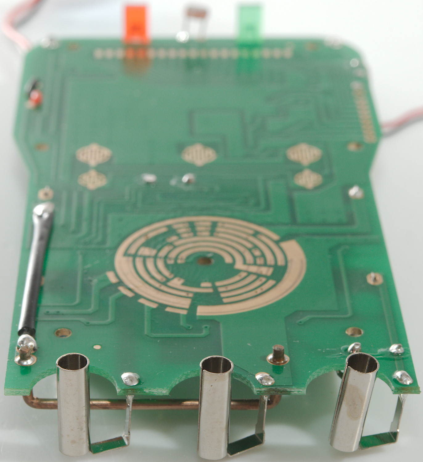
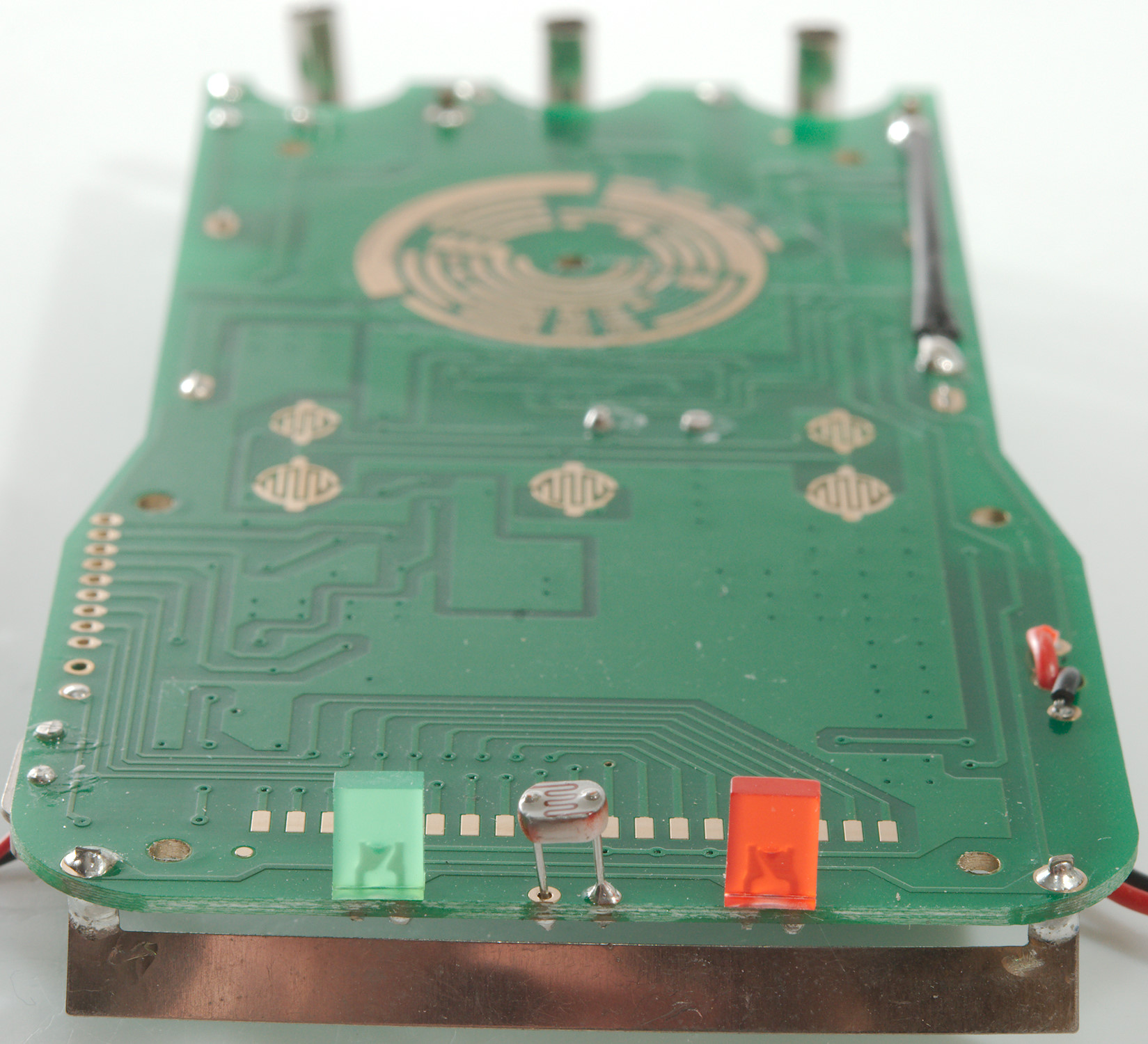
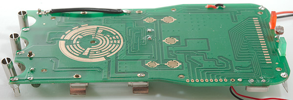
The NCV antenna at the front is tied to ground with a couple of resistors (R28, R29, R30: 3x10Mohm). The meter uses a 3V regulator (IC2: 7530-1). There is 3 transistors, one (T4) for the two leds, one for backlight (T5) and one for buzzer (T3). The trimpot is probably to adjust the reference.
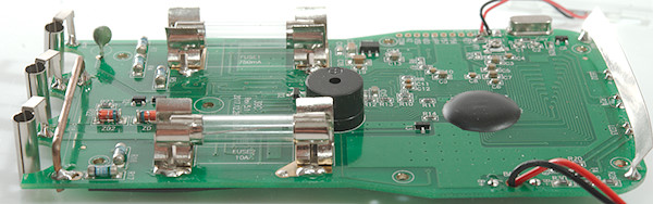
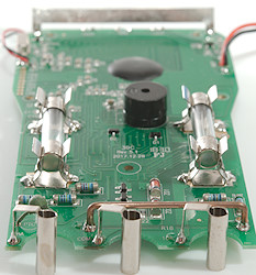
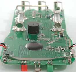
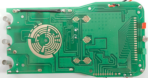
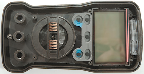
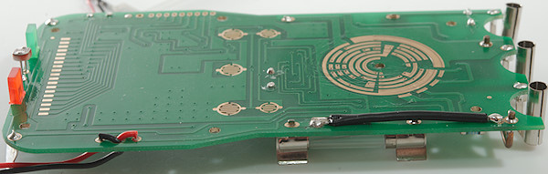
There is only two leds and a LDR resistor on this. There is also a wire to move 10A current to the fuse, generally it is fine to use a wire for this, but in this case the wire is placed above the other leg of the fuse, i.e. a hot fuse may melt the isolation and short itself, this is very bad. Generally the fuses are not soldered very well into the circuit board, only one side of the fuse holder goes through the circuit board.

Conclusion
As usual the CAT rating is wrong, it cannot be 600V with 250V fuses.
The meter has a nice selection of ranges and good precision, but it is not very well protected. The uA and mA range and the battery ranges may get damage by over voltage/current, the fuse will not protect them very much, especially in the 1.5V battery range it is easy to blow the shunt resistor. The 10A range may short out its fuse. In off the input is partially shorted, this is also problematic.
The meter may be used for a hobby meter, it is best to keep it well away from high energy. I do not expect the current/battery ranges will survive many mistakes (The resistors will get damaged).
Notes
How do I review a DMM
More DMM reviews