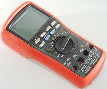
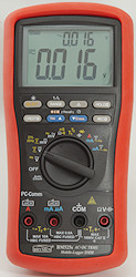
DMM Brymen BM525s
This is one of the advanced Brymen meter with good precision, logging and PC connection (Must be bought separately).
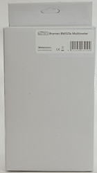
The meter arrived in a white cardboard box without any text on it.
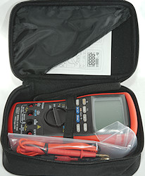
Inside was a pouch with everything in it.
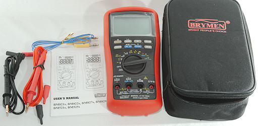
The box/pouch included the meter, two probes, a thermocoupler (Meter supports two) and the manual (It can also be downloaded).
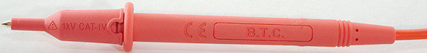
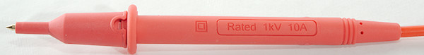
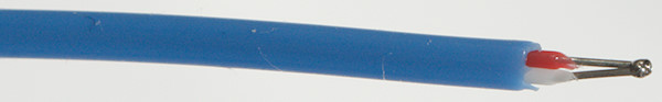
Probes are branded with B.T.C. and has removable tip covers.
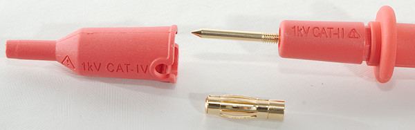
The probes are rated for up to CAT IV 1000V like the meter.
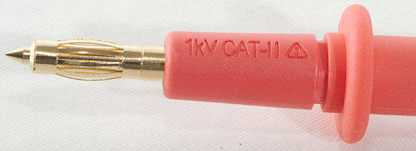
It is possible to screw a banana plug onto the tip, but then the tip cover cannot be used.
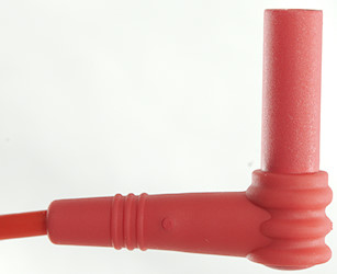
The plug is fully shrouded and standard probe plug size.
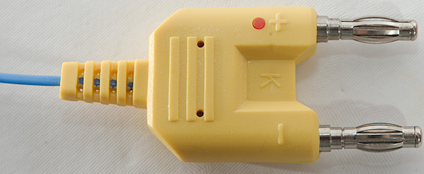
A standard thermocoupler with a standard dual banana connector.
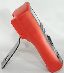
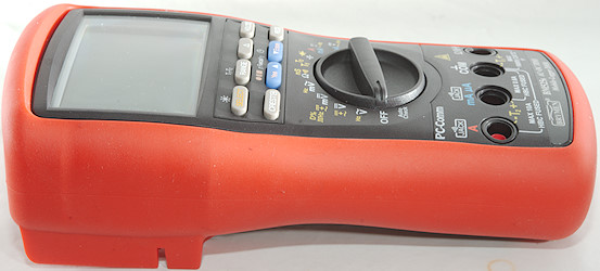
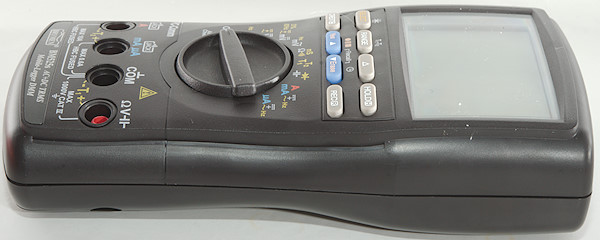
The meter is heavy and the tilting bale can hold it while the range switch is used or the buttons is pressed.
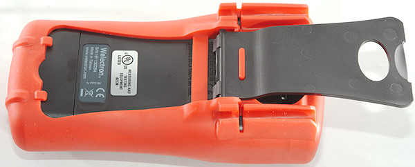
The tilting bale can be moved a bit and then be used to hand the meter on.
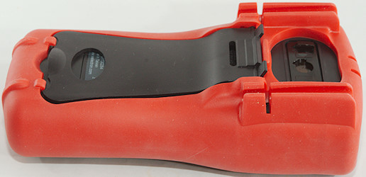
The PC connection is on the back with an optical link.
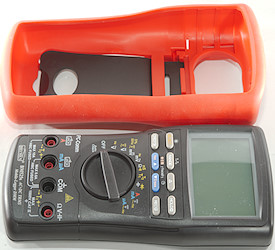
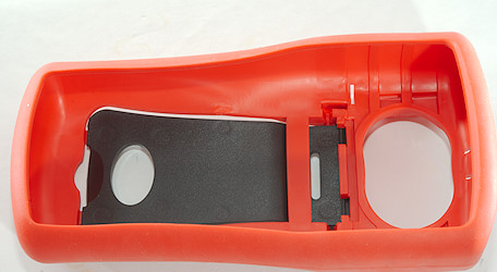
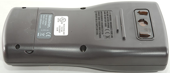
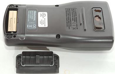
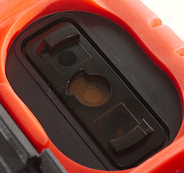
The rubber sleeve must be removed to replace the battery
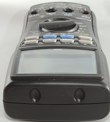
Display
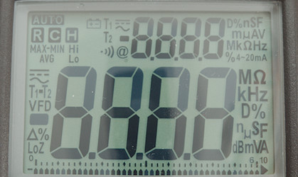
The above picture shows all the segments on the display.
There is two 4 digit displays and a bargraph. The small display and the bargraph will only be used in some ranges, see end of this chapter. There are also a few segments that is not used on this model.
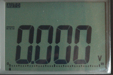
Normal DC voltage with voltage and bargraph.
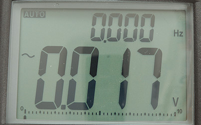
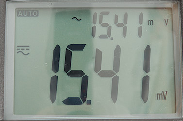
In AC modes the small display with frequency will supplement the large display.
With this display the meter could not maintain the bargraph.
The bargraph will not be show when the secondary display shows voltage or current.
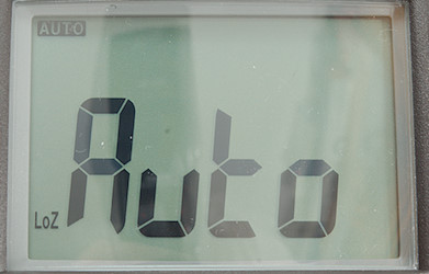
The meter has a special auto position where it will show voltage AC or DC and ohms.
Dual and single display functions (After / is small display):
VAC: VAC/Hz, Hz/VAC
VDC: VDC, VDC/VAC, DC+AC/VAC
mVDC: mVDC, mVDC/mVAC, mDC+mAC/mVAC, Hz, Duty Cycle
mVAC: mVAC/Hz, Hz/mVAC
Temp: T1, T2, T1/T2, T1-T2/T2 (Use RANGE to select)
mA: mADC, mADC/mAAC, mDC+mAC/mAAC, mAAC/Hz
A: ADC, ADC/AAC, DC+AC/AAC, AAC/Hz
uA: uADC, uADC/uAAC, uDC+uAC/uAAC, uAAC/Hz
Functions
Buttons (Select and a few other are remembered):
- Select: Select between the different modes on each position of the range switch, hold down to activate background light. Meter will remember the selection and use it next time the range is selected.
- Range: Switch to manual range and select range, hold down to activate automatic ranging again. In temperature mode it will select different combinations of thermocouplers.
 : Shows values relative to current value.
- Hold: Freeze the display, press again to release.
- Crest: Peak mode, will record and show fast min/max. Use button to change between max/min/max-min. Hold down to end mode.
- Yes: Hold down to start logging, confirm logging with a fast press or use Erase to clear all old logs before starting.
- Erase: Hold down to set logging interval from 0.05, 0.1, 0.5, 1, 2, 3, 4, 5, 10, 15, 30, 60, 120, 180, 300, 600 seconds (Use arrows to select, hold down to confirm). This setting is reset to fastest setting every time mode is changed.
- Rec: Minimum/maximum mode, will record min/max values. Use button to change between actual/max/min/max-min. Hold down to end mode.
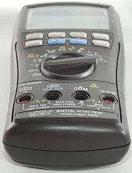
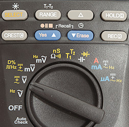
Rotary switch:
- Auto check: VDC, VAC and ohms, meter will automatic select
- Off: Meter is turned off.
- VAC: Measure AC voltage and frequency
- VDC: Measure DC voltage, AC voltage and AC+DC voltage.
- mVDC: Millivolt range, measure DC voltage, AC voltage, AC+DC voltage, frequency and duty cycle.
- mVAC: Millivolt range, measure AC voltage and frequency
 : Resistance and continuity, the nS makes it possible to measure very huge resistance values.
- T1 T2: Measure temperature with one or two thermocouplers, can also show difference between them.
 : Capacitance and diode range.
- A mA: This is either mA or A depending on where the probe is connected. It will measure DCA, ACA, ACA+DCA and frequency
- uA: The uA range. It will measure DCA, ACA, ACA+DCA and frequency.
Input
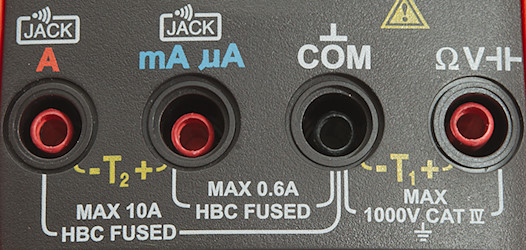
- A: High current, maximum current is 10A, also ground for second thermocoupler.
- mAuA: The lower current ranges and + input for the second thermocoupler.
- CON: The common terminal for all ranges.
- xxx: All other ranges.
Measurements
- Volt and frequency
- Frequency input (mVDC) has a trigger point around 1.2V
- At 10mVrms frequency input (mVAC) range is from 2Hz to 80kHz
- At 100mVrms frequency input (mVAC) range is from 2Hz to 58kHz (It is about the same at 1Vrms)
- At 1Vrms input on mVDC range (logical frequency), frequency range is from 2Hz to 180kHz
- At 2Vrms input on mVDC range (logical frequency), frequency range is from 2Hz to 1.2MHz
- Duty cycle works from 1% to 99% at 10kHz with 4Vpp, precision is within 0.4
- 1 VAC is 5% down at 7kHz (RMS will not work at the frequency).
- Auto range works when doing min/max, peak and relative.
- Max/min (Rec) needs about 600ms to capture a voltage.
- Peak (Crest) needs about 0.7ms to capture a voltage.
- Auto mode requires 1.2V DC to select voltage DC.
- Auto mode requires 0.5V AC to select voltage AC.
- Large AC values on DC ranges will prevent the meter from showing a value, except if dual display AC and DC is selected.
- Input impedance is 10-10.5Mohm on DC
- AC input has a capacitor
- The DCV & DCmV range has two paths: Directly DC volt and True-RMS volt, they will not show exactly the same value.
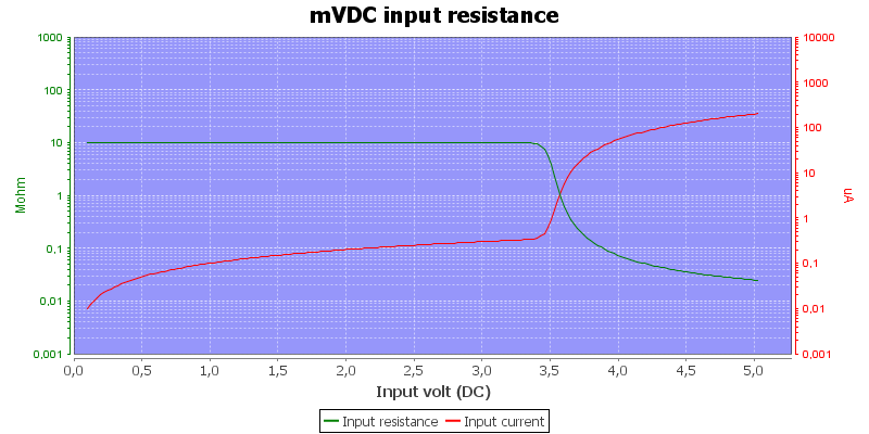
- mV DC/AC has 10Mohm input impedance up to about 3V, then it drops to 20kohm at 10 volt and 4kOhm at 35 volt.
- Frequency input is 10Mohm up to 3 volt then it drops to 20kohm at 10 volt and 4kOhm at 35 volt.
- Rated overload protection on V ranges is 1100VDC/VAC and 12kV transient.
- Rated overload protection is 1000VDC/VAC and 12kV transient in mV range .
- Current
- Overload protection in uA and mA: 0.44A/1000V 10x38mm fuse
- Overload protection in A: 11A/1000V 10x38mm fuse
- There is an audible warning and display shows "InErr" when using non current ranges with a probe in mAuA or A input.
- Ohm, continuity, diode and capacitance
- Ohm needs about 2s to measure 100ohm
- Ohm is 1.0V open and 0.17mA shorted
- Continuity is very fast (Below 10ms, but not latched making it difficult to use it faster).
- Continuity beeps when resistance is below 250ohm
- Continuity is 1.2V open and 0.17mA shorted
- Conductivity (nS) is 1.2V open and 0.3uA shorted
- Diode range uses 3.1V, max. display is 2.0000V at 0.13mA, max. current is 0.37mA shorted
- 10uF takes about 3 seconds to measure.
- 11000uF takes about 12 seconds to measure.
- Rated overload protection is 1000VDC/VAC and 12kV transient.
- Miscellaneous
- Current consumption of meter is 4.6mA and 4.8mA when logging (35mA with backlight)
- Current consumption when logging with an interval of 30 seconds or more will drop to 2.9mA after the first 5 minutes.
- Meter works down to 4.0V where it says "InErr", battery symbol show at 6.8V.
- The meter reading is stable down to 5.7V on battery.
- Backlight is stable until meter reports "InErr".
- Maximum logging speed depends on range and varies between 0.05s (20 times/sec) to 2s
- Meter can save up to 87000 single logging values or 43500 dual logging values (dual is used when dual display is on), this can be split in multiple sessions.
- The meter sometimes need a couple of updates before the reading is fully correct.
- Viewing angle is good
- Display updates around 5 times/sec.
- Bargraph updates 60 times/sec
- When logging bargraph is used to indicate that.
- Backlight will turn off in 32 seconds
- Backlight has a few shadows, they do not make it harder to read the display.
- Will automatic turn power off in about 30 minutes without any warning.
- Standard probes fits perfectly into sockets on meter.
- Weight is 638g without accessories, but with sleeve and batteries.
- Size is 207 x 103 x 64mm.
- Probes
- Probe resistance 26mOhm for one.
- Probe wire is soft and 100cm long.
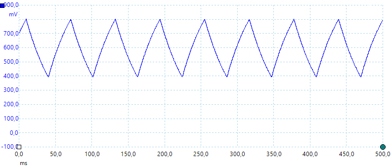
A look at the capacitance measurement waveform.
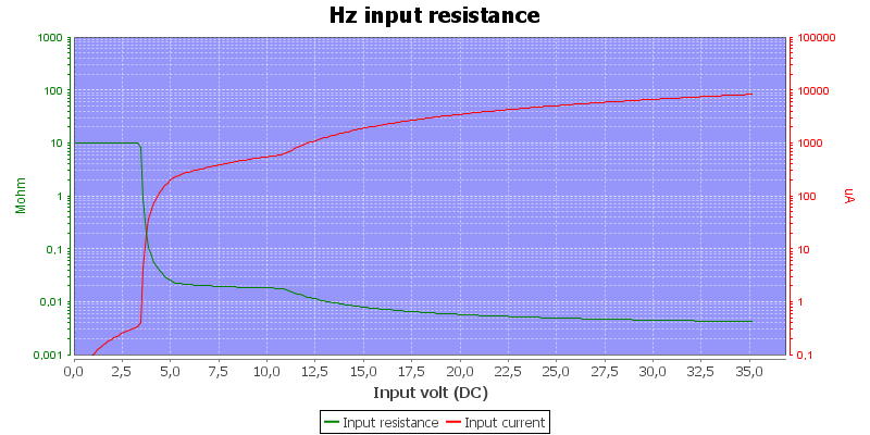
Frequency input resistance.
The 60mV DC is supposed to have a offset below 20uV, but it is more like 40uV
Software
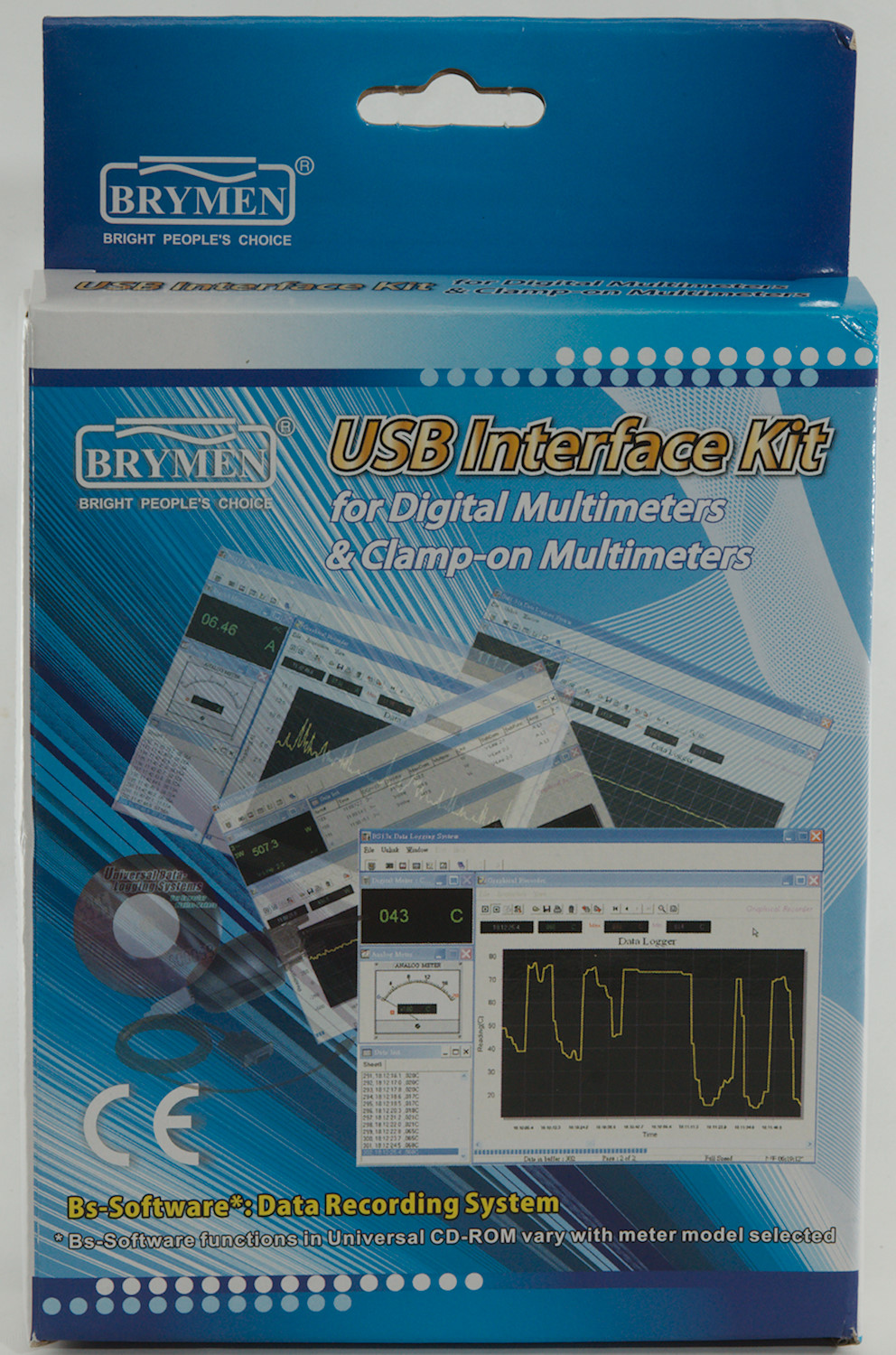
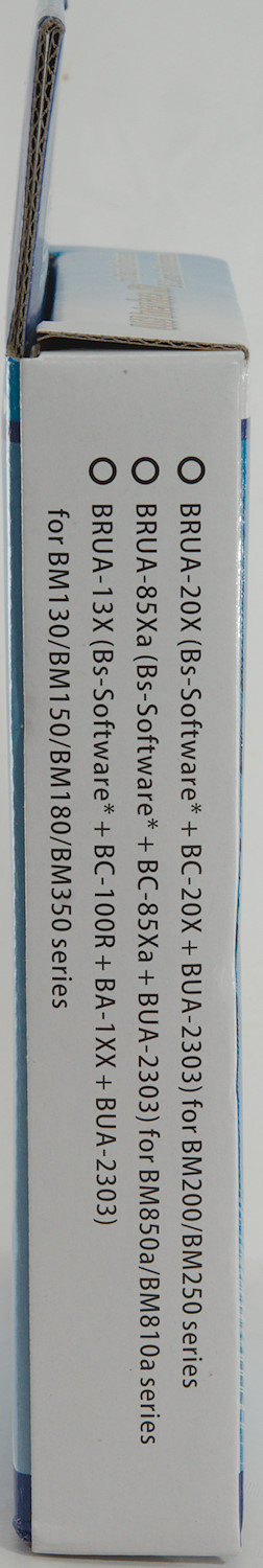
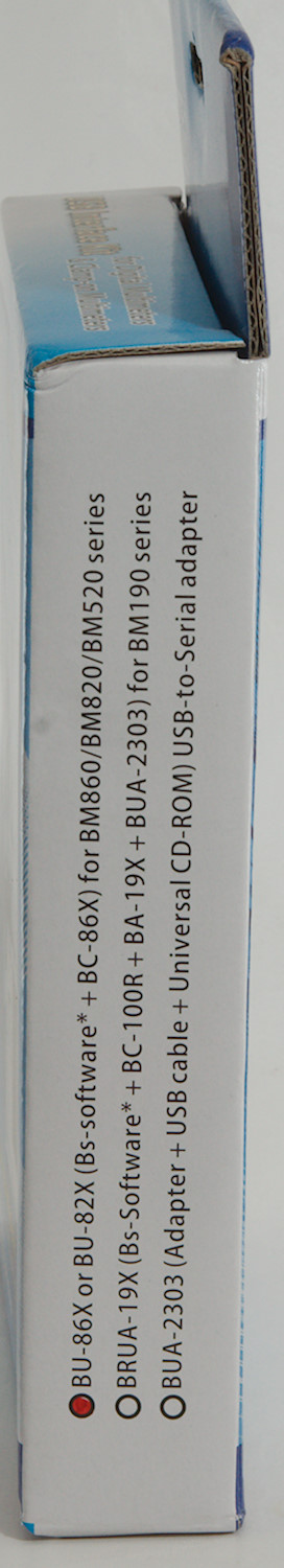
The software must be bought separately.
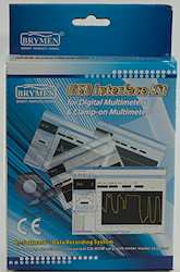
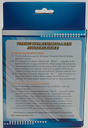
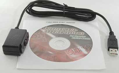
The box only includes a cable and a CD. The CD contains software for many different meters and also files describing the data format (It is the display segments, not digits that is transmitted).
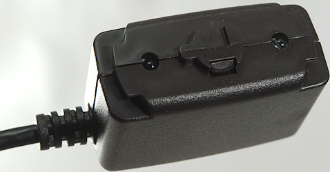
The opto adapter has two leds and some mechanic to lock it securely in place.
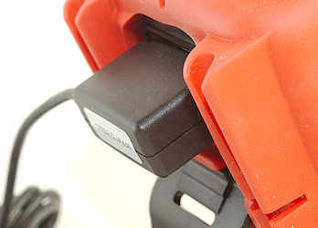
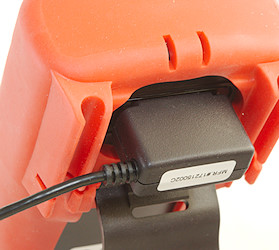
Here it is mounted on the meter.
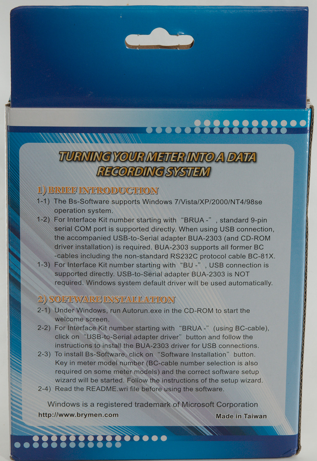
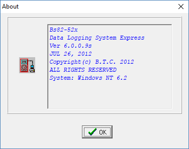
The software is not exactly new or frequently updated, but it worked fine on my Windows 10 computer.
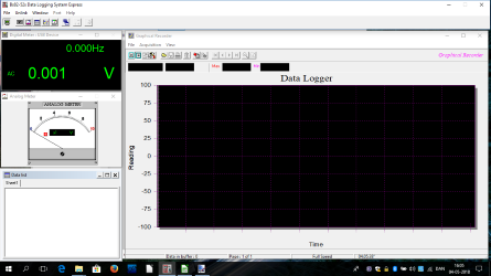
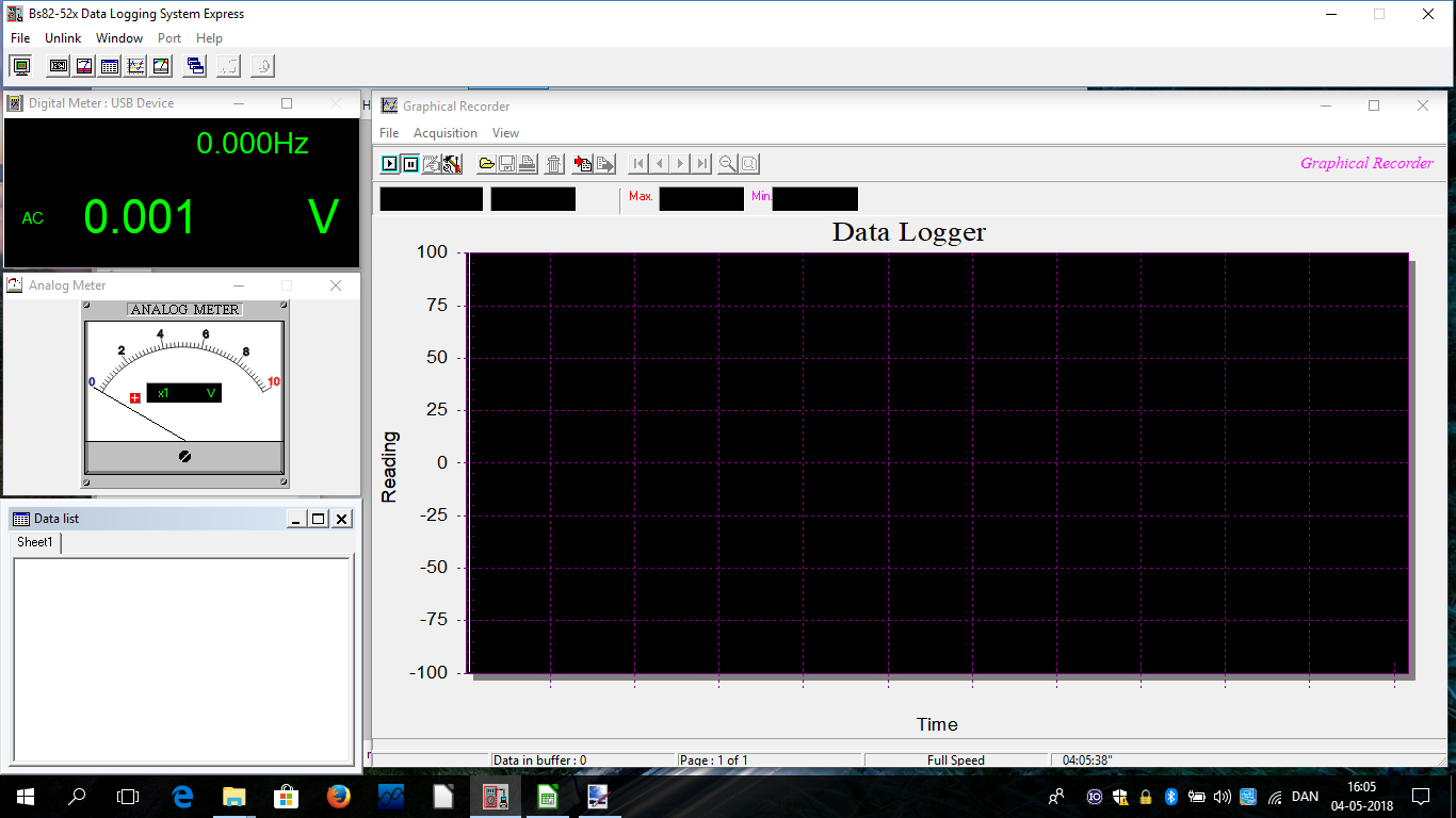
The software is one top bar and initially four independent windows.
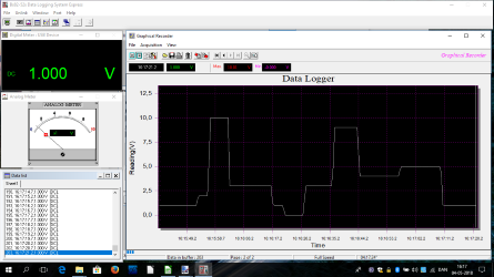
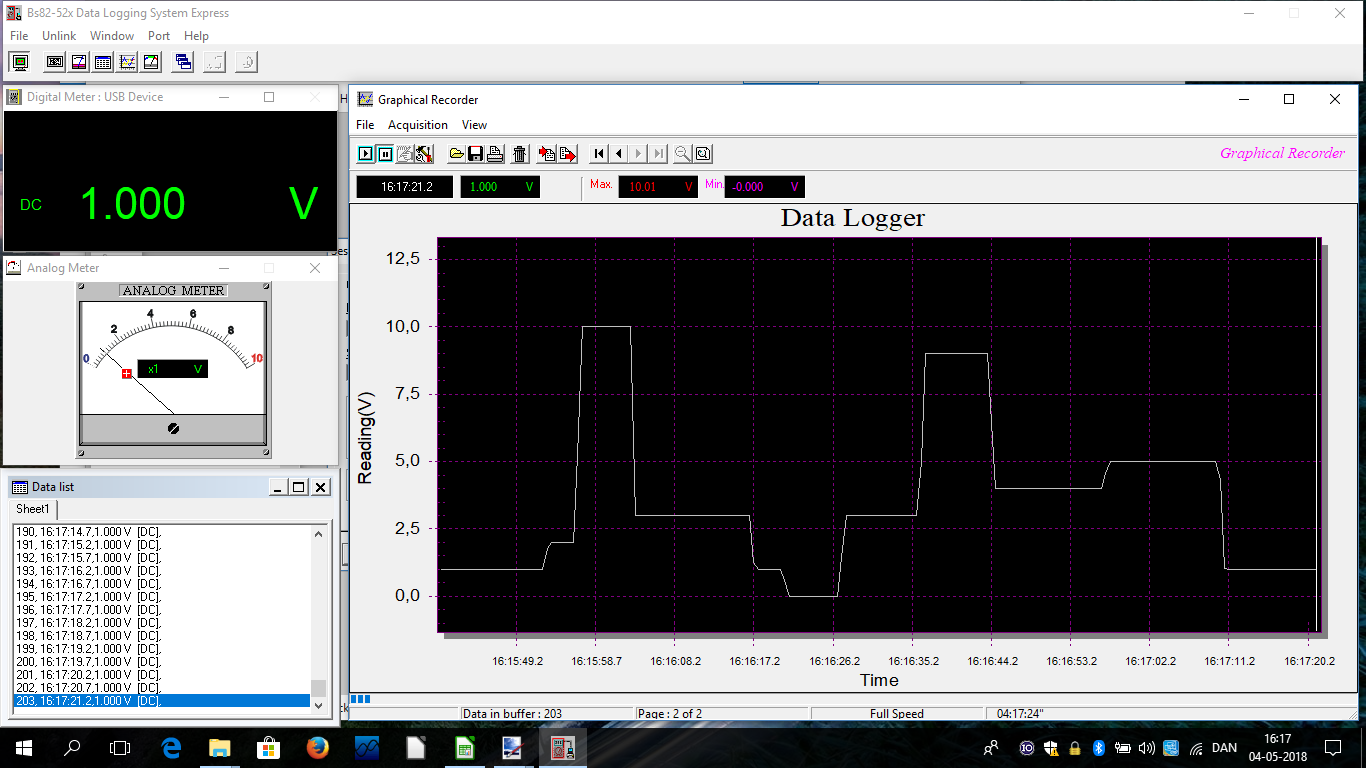
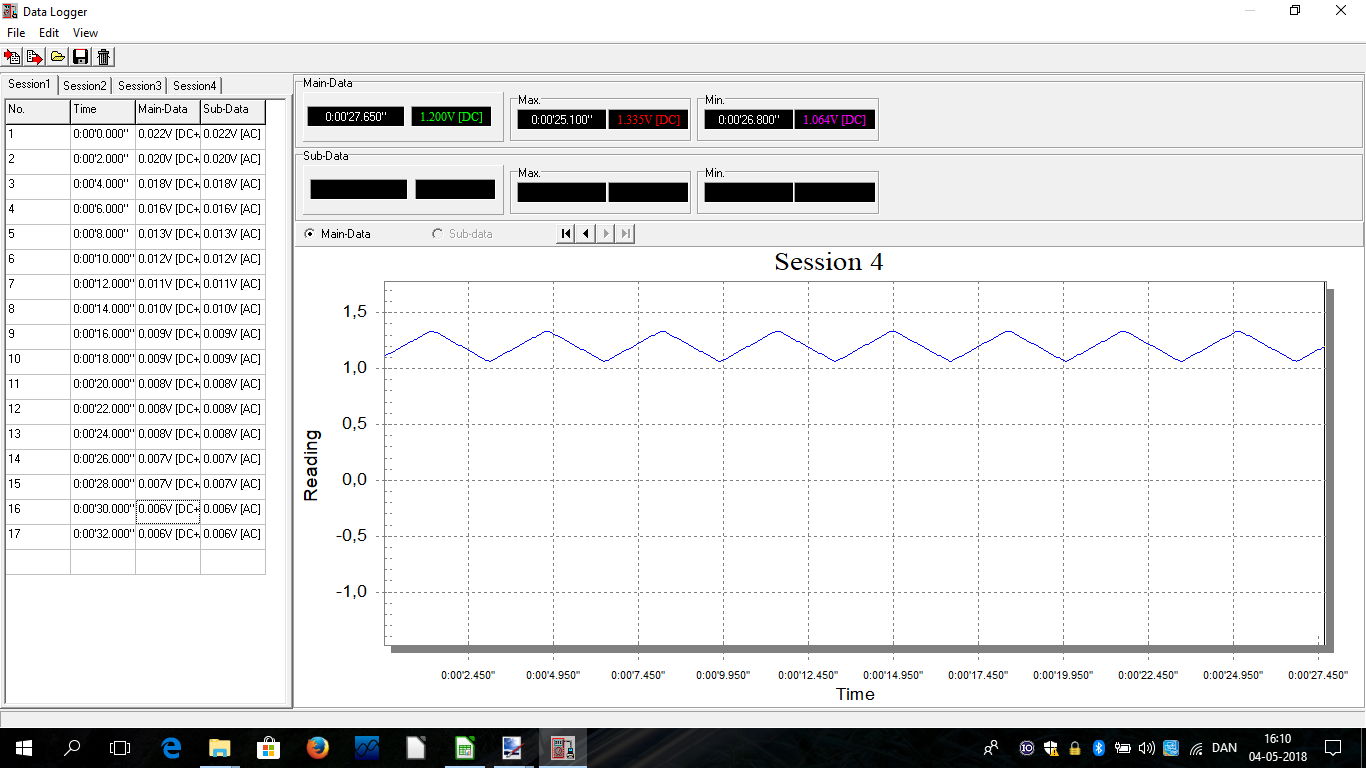
Here I am connected to the meter and reading data.
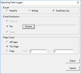
The data can be saved from the chart window in either an internal format or exported to a image or CSV file.
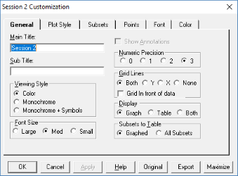
It is possible to do some layout adjustments (Double click on chart to get these settings).

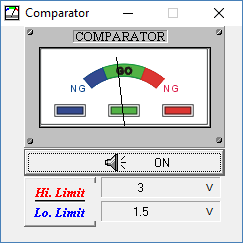
The software also has a comparator window for checking if a value is inside some tolerances.
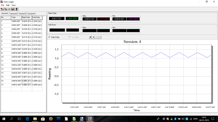
The log data saved in the meter can be downloaded. All session will be downloaded at once, they can be viewed and saved separately. It is only possible to see one curve at a time, either from the main display or from the secondary display, both cannot be combined in the chart.
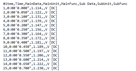
The CSV file is fairly easy to read, except the time format looks a bit special.
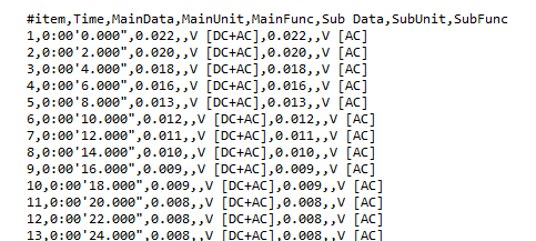
And if the meter is using the dual display it will log two sets of data for each line.
The empty field between the value and the unit is used to show u,m,k,M when needed.
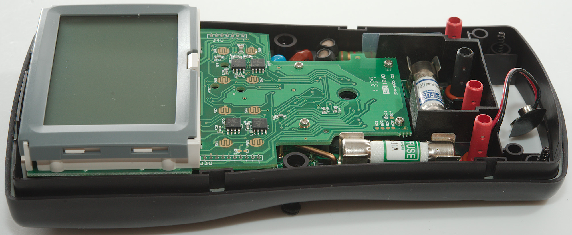
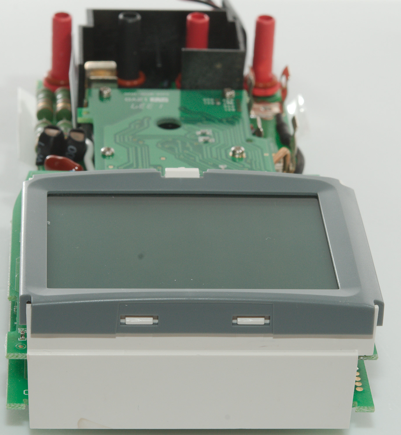
Tear down
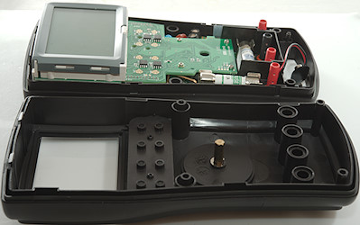
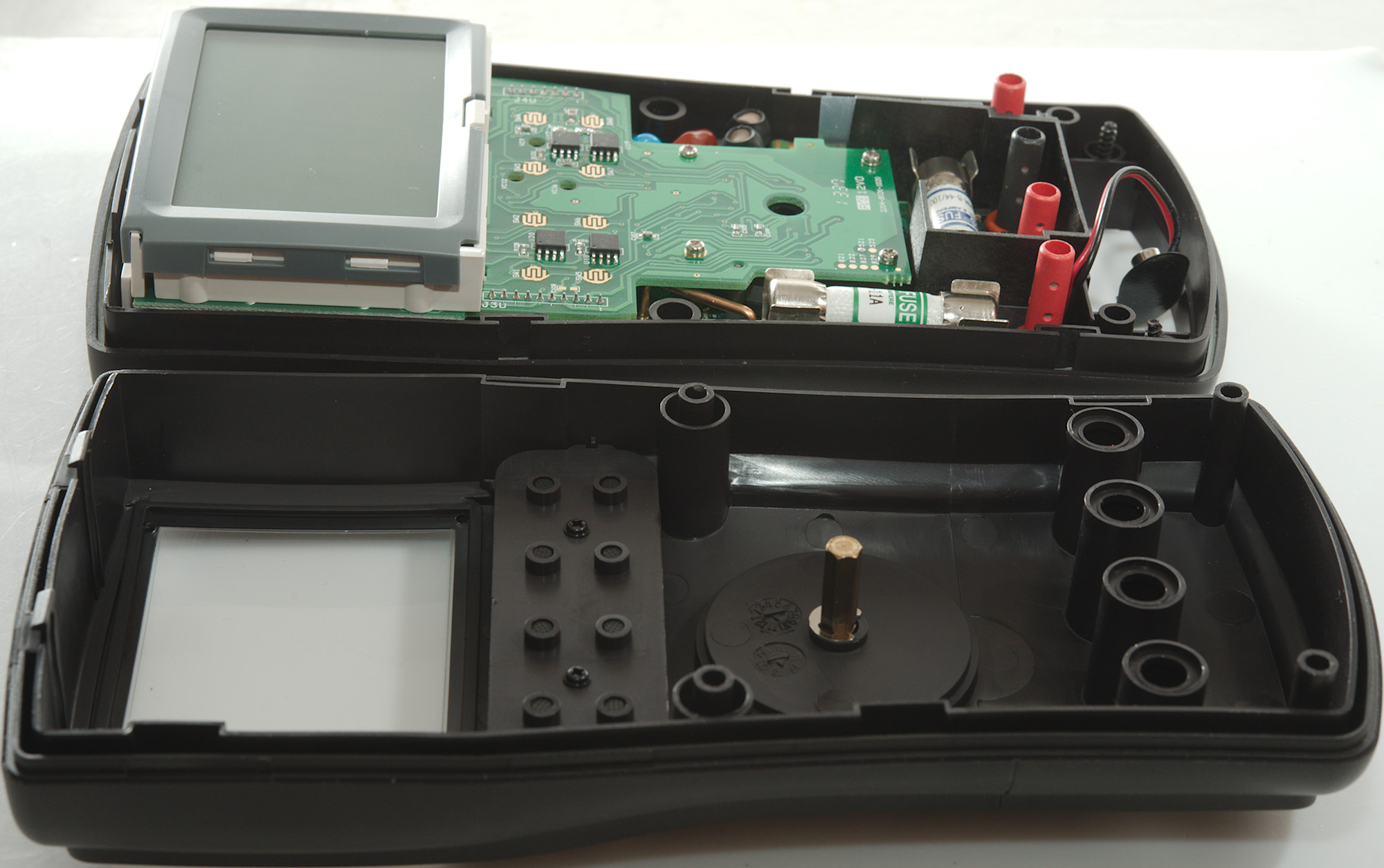
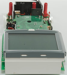
4 screws and the front could be removed (This time it was not the back). The screws do not fall out, but stays in the holes.

I had to remove one small screw at the COM terminals base, then I could take the electronic out of the bottom.
The buzzer is placed below the shield with holes for springs to connect.
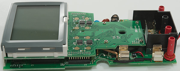
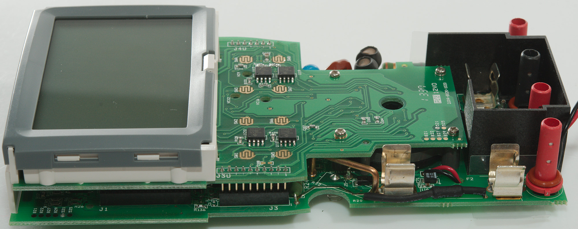
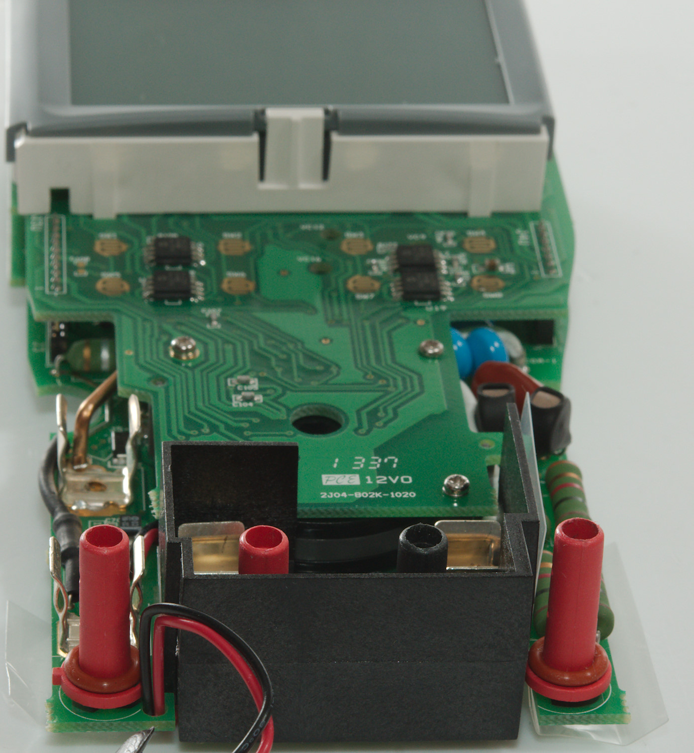
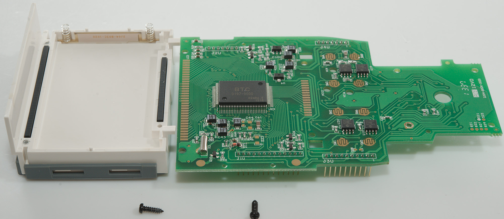
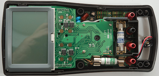
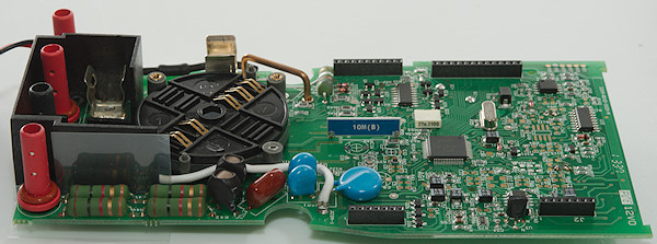
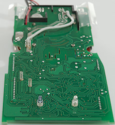
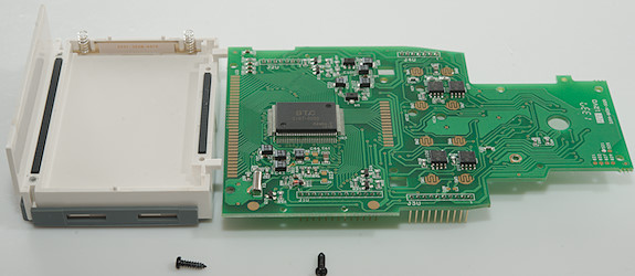
The meter has two circuit board on top of each other
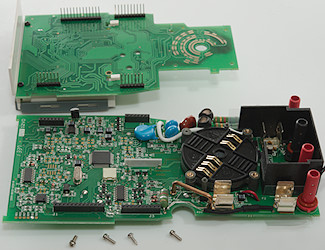
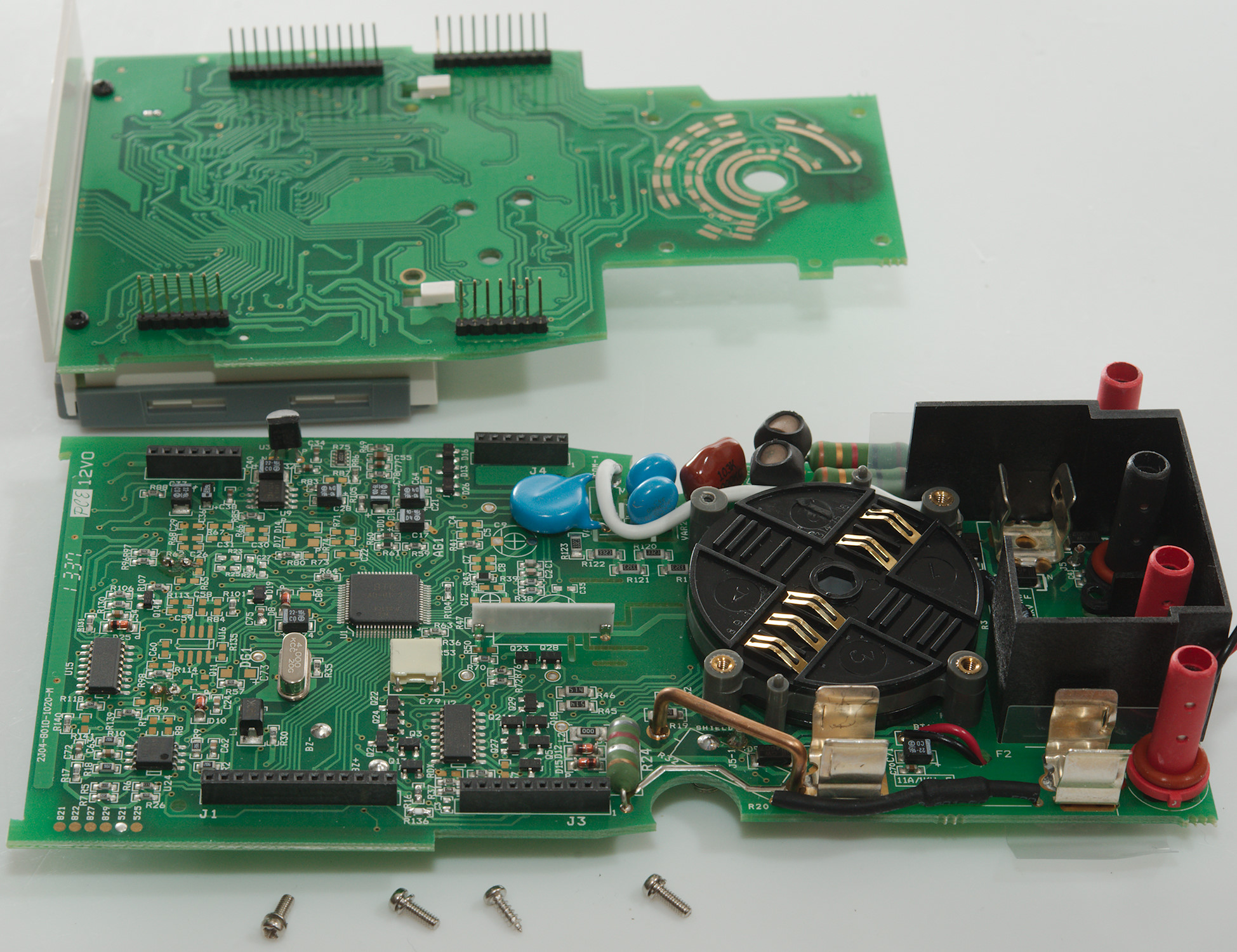
Removing four screws from the top circuit board and I could lift it off. One of the screws was a self tapping, the other machine screws.
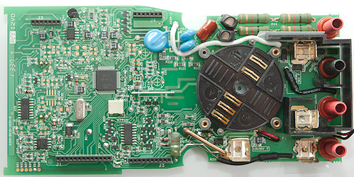
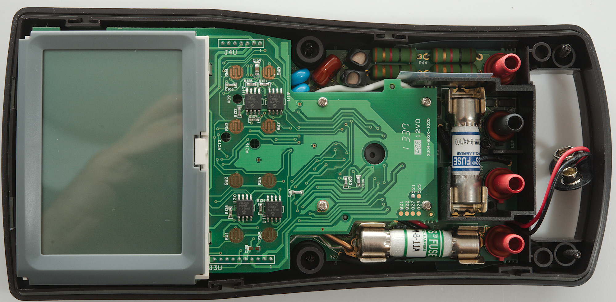
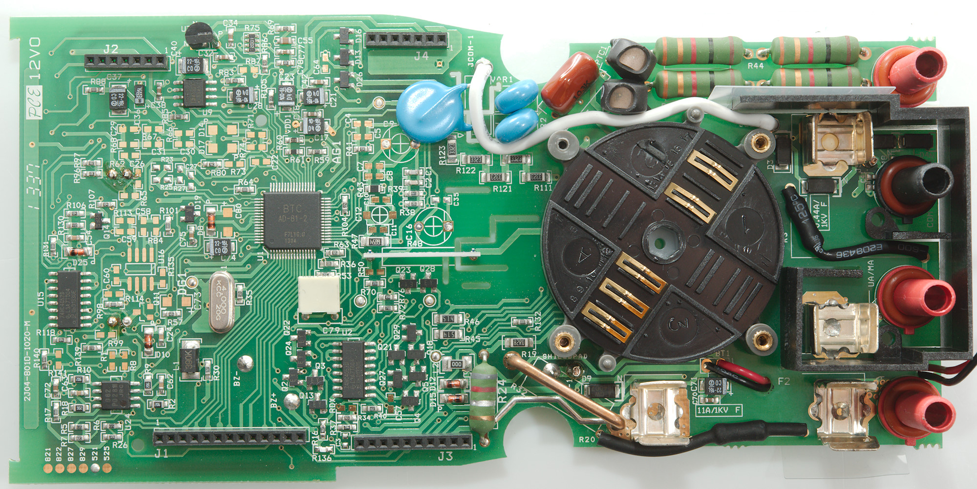
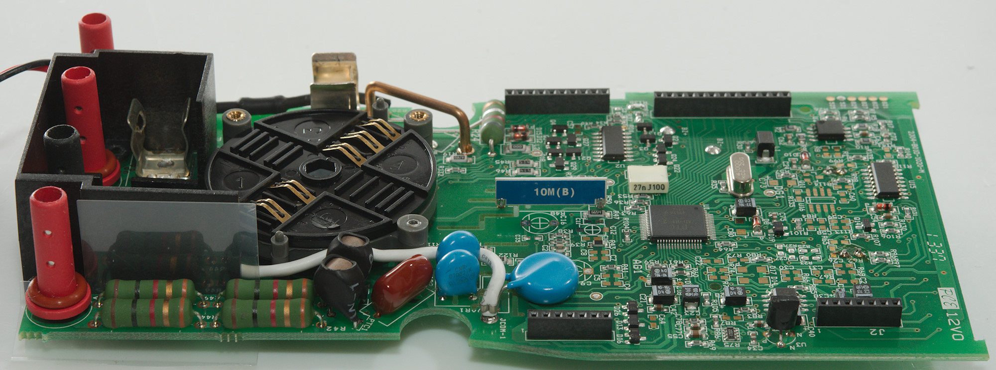
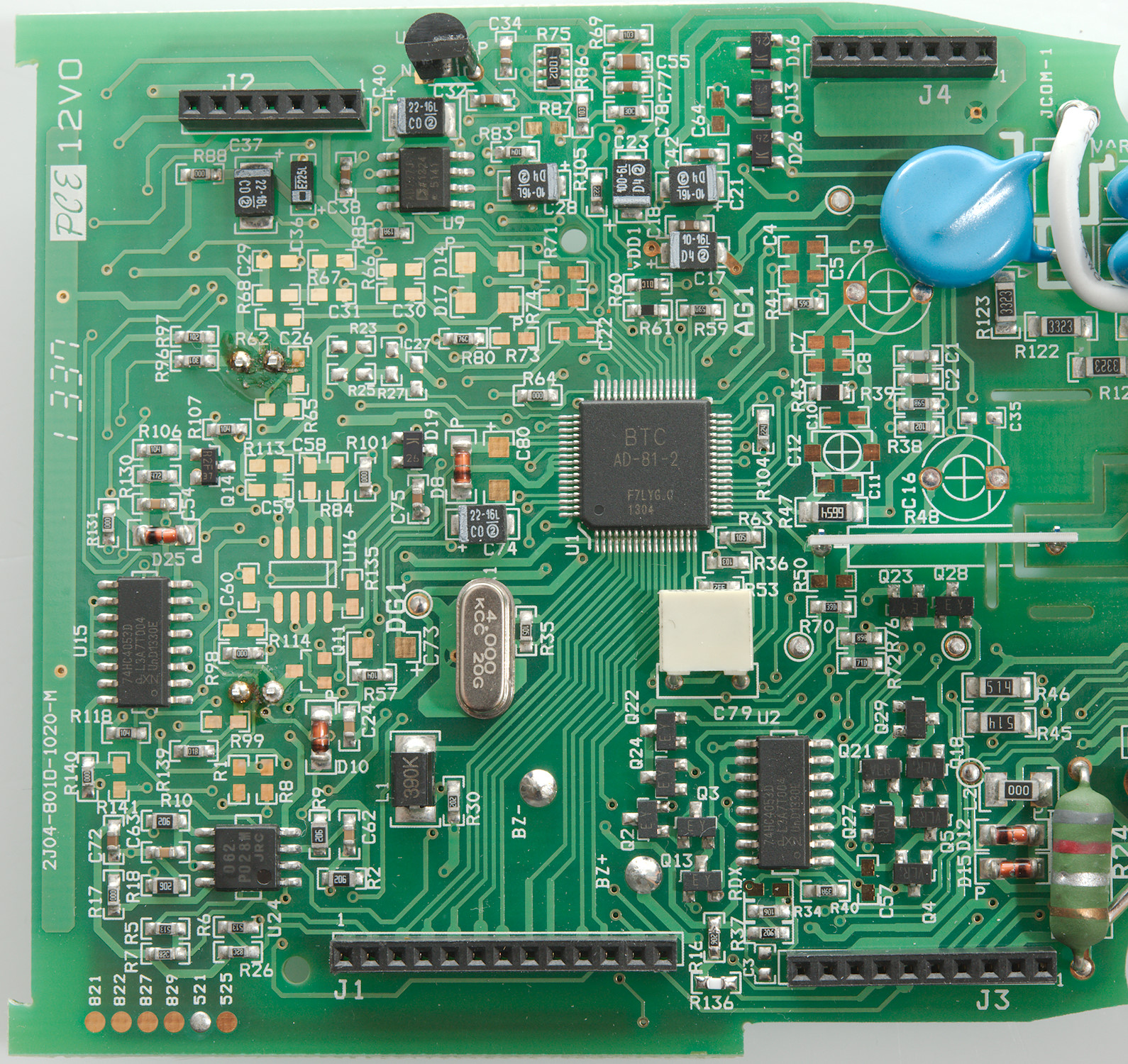
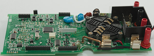
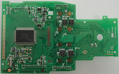
The circuit board has slots in it and plastic sticking up in some of the slots for isolation. The two current terminals uses slit sockets to detect a plug. There is a resistor (R3 & R20: 2x10MOhm) from each of them, the resistor is covered in heatshrink and has fairly long leads. Around the COM socket is the 4 overload protection diodes (D1..D4) for uAmA range.
The voltage input has two paths, both starts with two resistors (R42, R44, R49, R52: 4x1kOhm), a PTC (PTC1 & PTC2) for each path, the a MOV (VAR1 & VAR2) followed by a common MOV (VAR3). The return path from the MOV is a wire. The AC input capacitor is between the PTC's and MOV's (C13: 10nF 1000V). Depending on range the output from the PTC's is switched to different parts of the circuit. There is the main voltage input resistor (R48: 10Mohm) or ohm and capacitance with current output and a lower impedance input (R111, R120, R121, R122, R123: 5X332kOhm).
There is also some transistor pairs for protection (Q22 & Q24, Q23 & Q28), but it looks like pairs is to low voltage for some function there are longer strings of transistors (Q2, Q3, Q13 & Q5, Q18, Q29, Q21, Q27).
The analog front-end (U1: BTC AD-81-2) is probably a lot of muxes and the ADC in a single chip. There is more muxes (U2, U15: 2x74HC4053). The RMS converter is another chip (U9: AD737J) and it is next to the reference (U3:LM185).
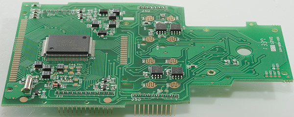
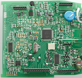
There is missing a lot of parts on the circuit board, that is because the same circuit board is used for multiple DMM models, see the circles with solder blobs in the lower corner, this is marked as a model 521.

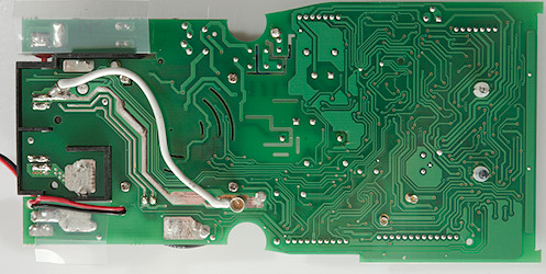
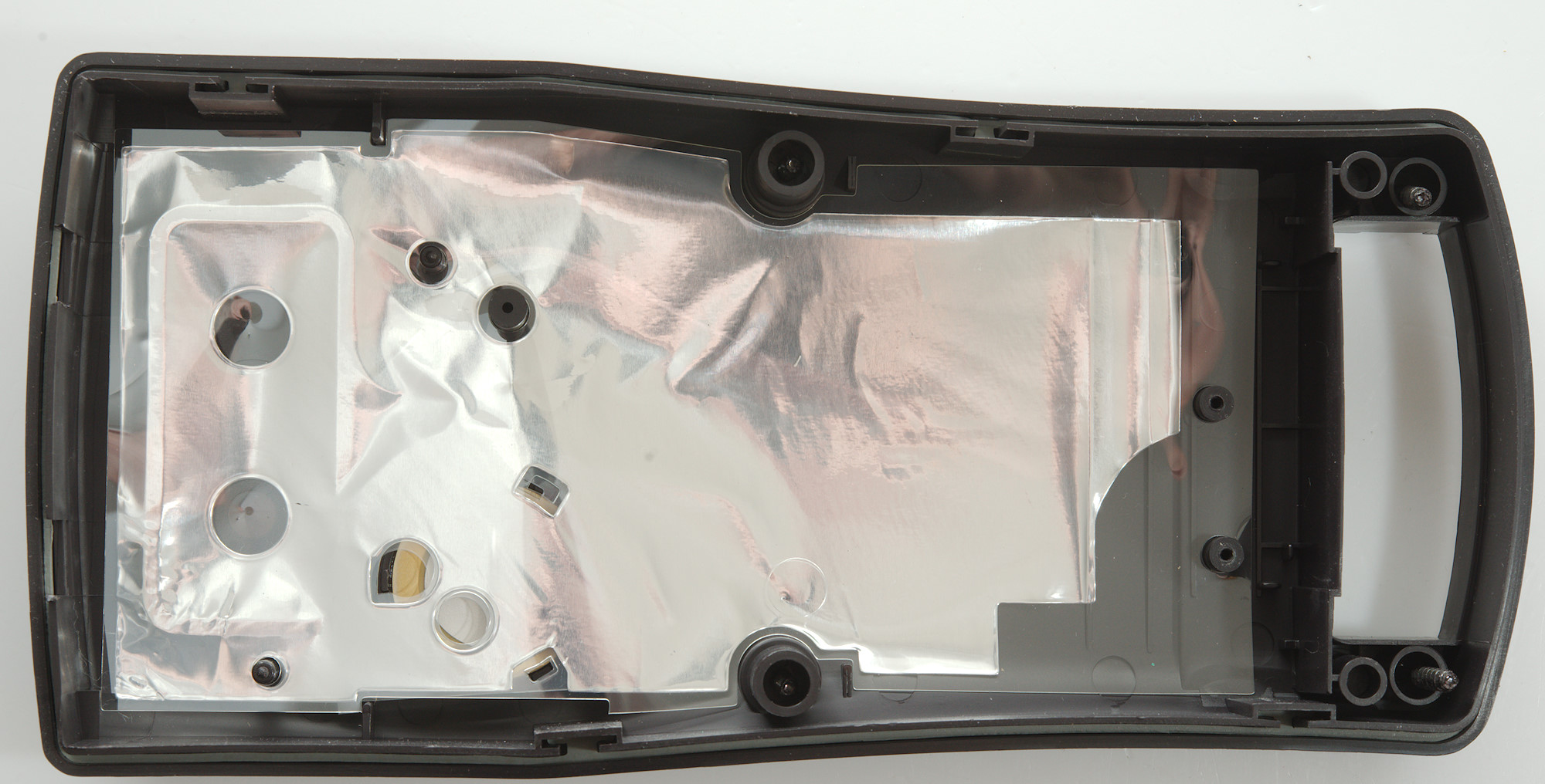
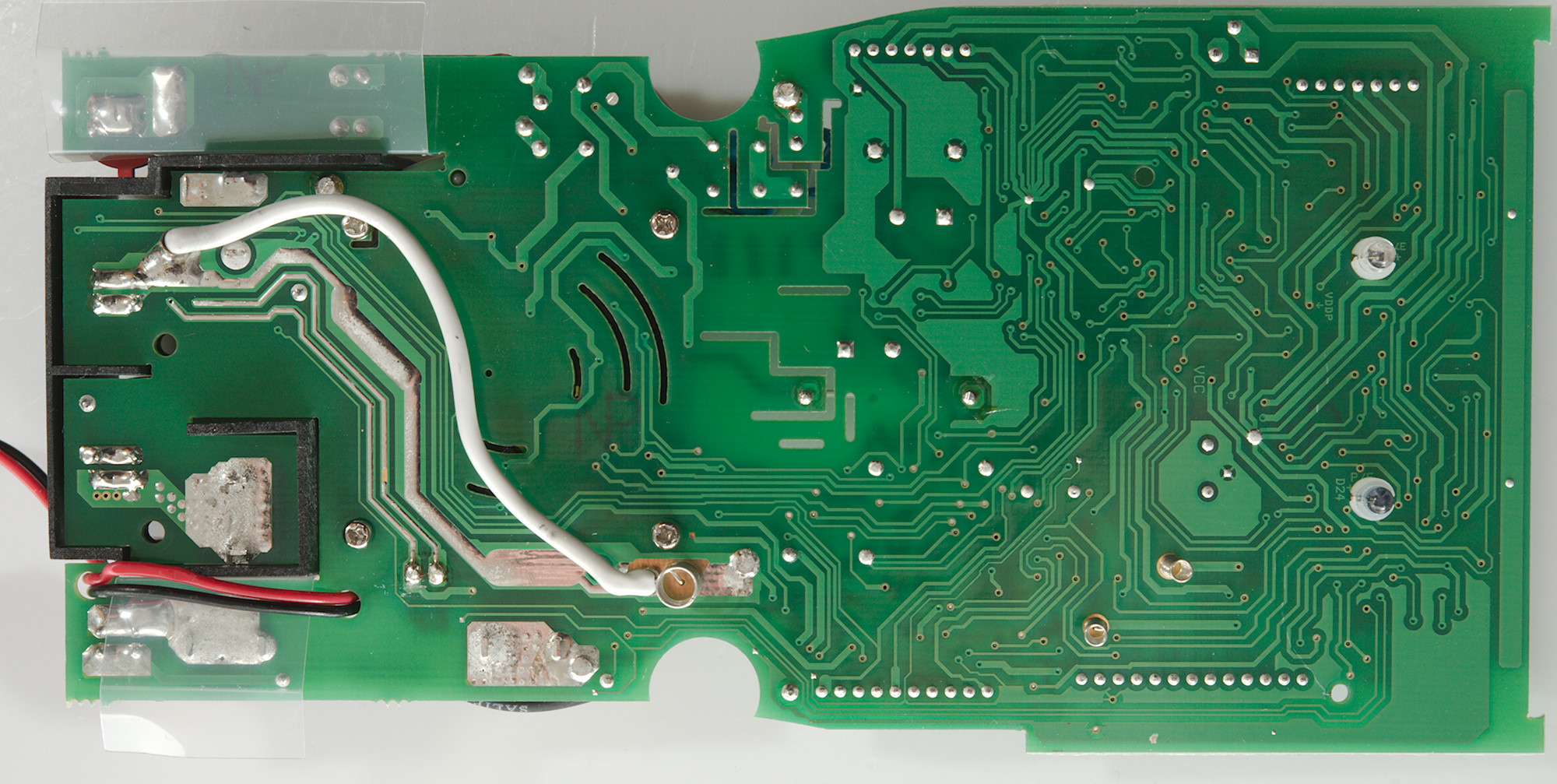
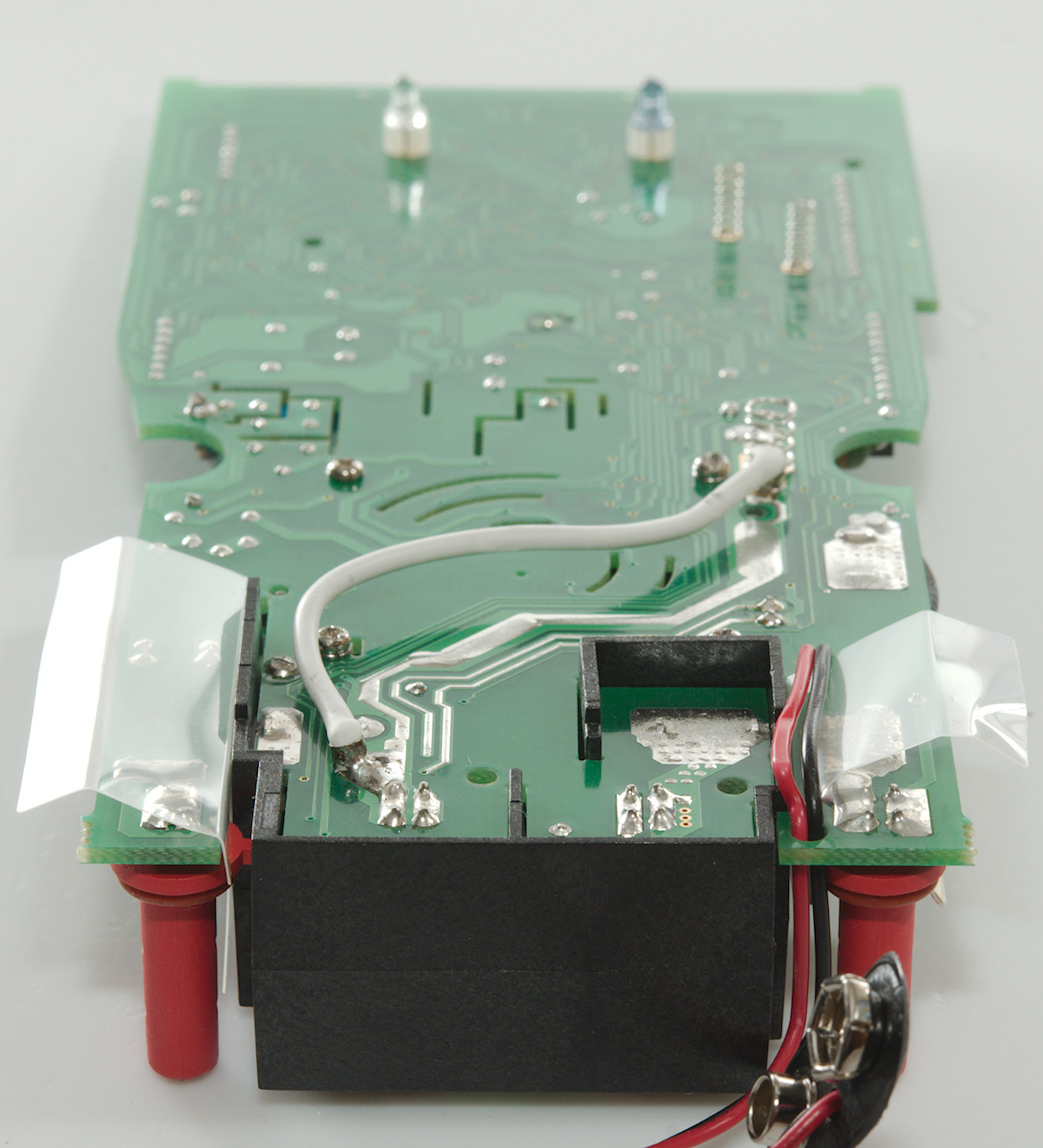
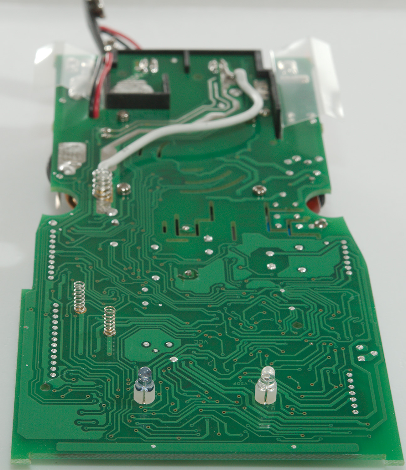
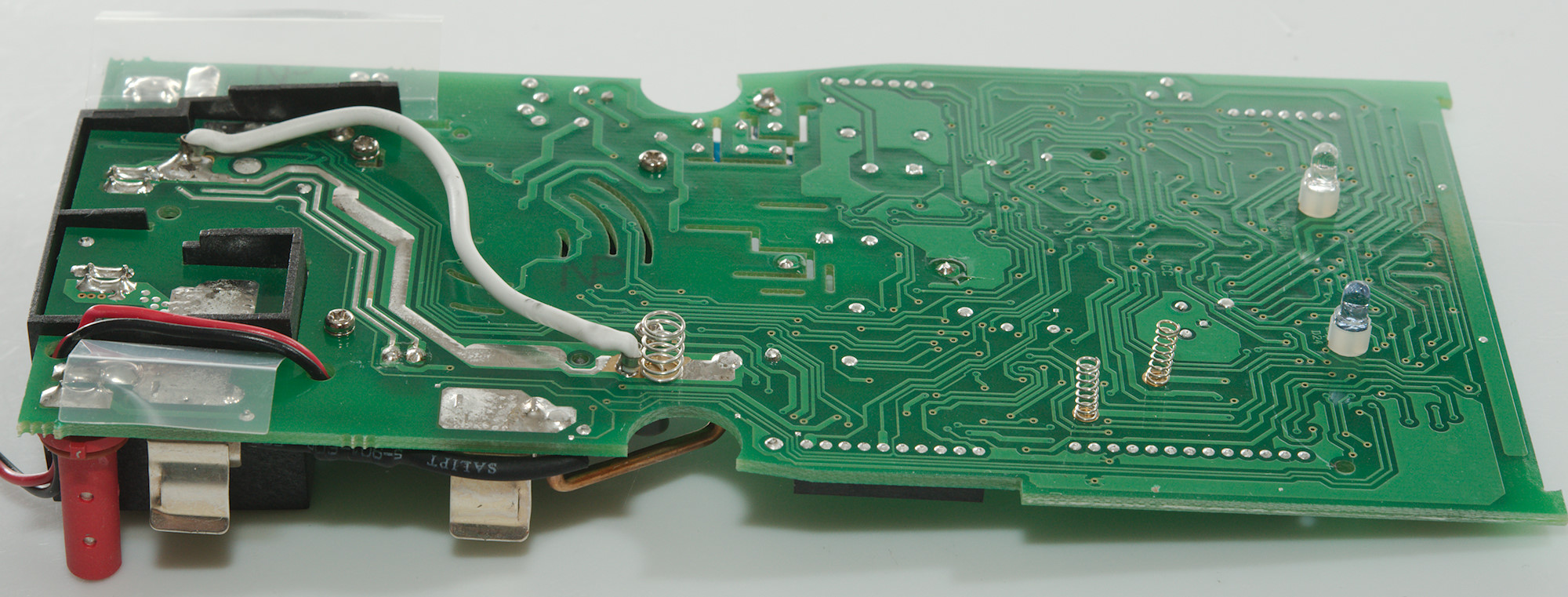
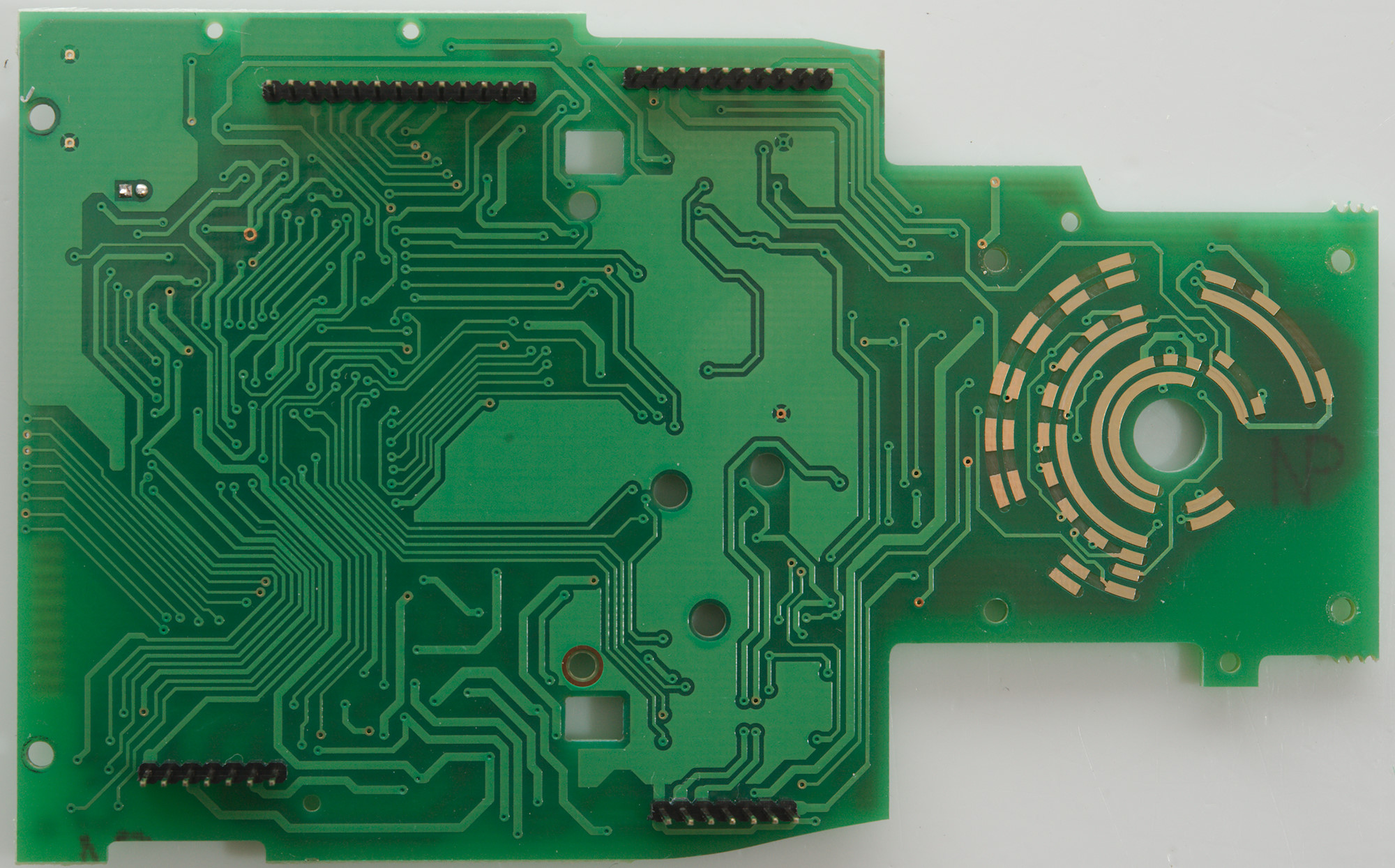
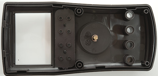
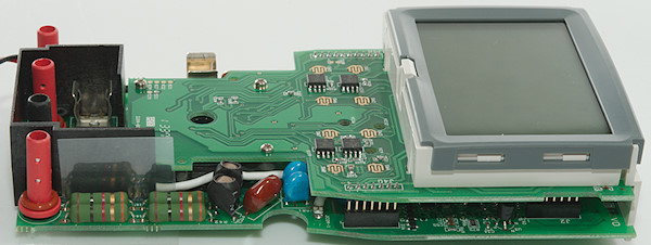
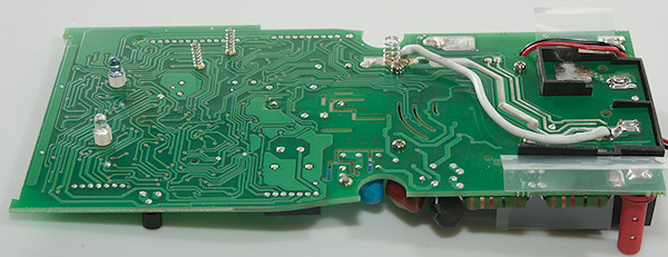
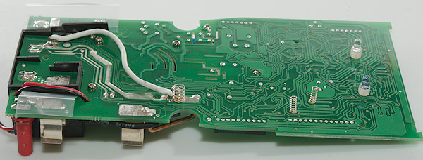
This side do not have many parts, there is 3 springs, two for the buzzer and one for the shield. Two diodes for the PC interface (IR transmitter and receiver diodes). and a wire to reinforce the ground from the 10A current shunt.
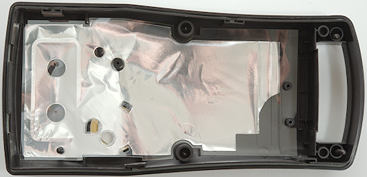
The isolation plastic is easy to see here, both the black shape and the two nearly transparent pieces.
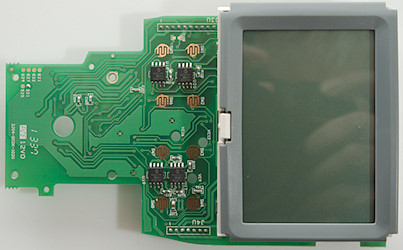
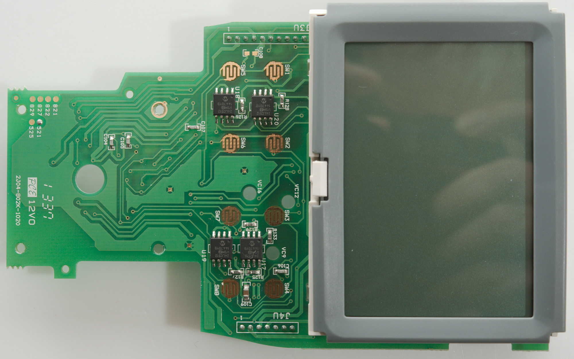
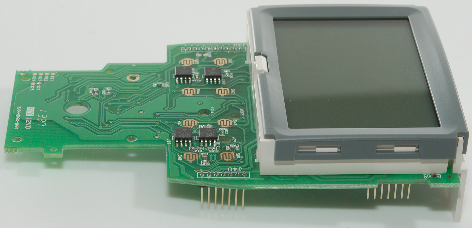
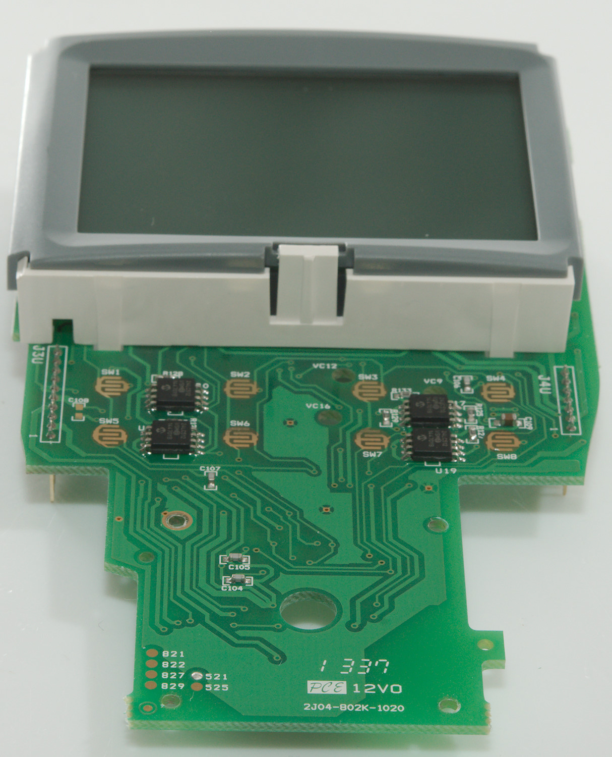
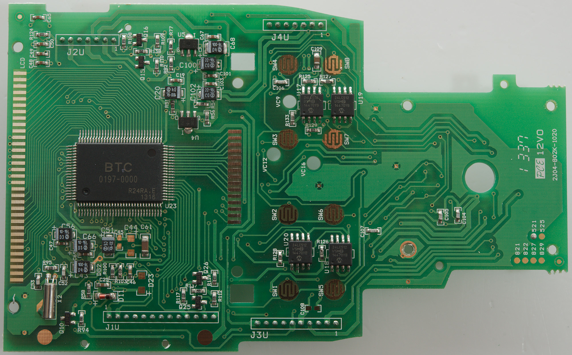
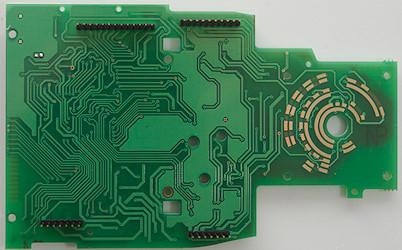
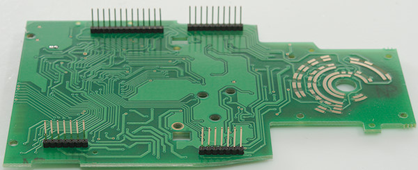
The display board has pads for all the buttons and some chips between them. The chips (U17..U20: 24LC512 8*64K) are EEPROM. This gives 3 bytes for a single value logging.
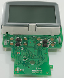
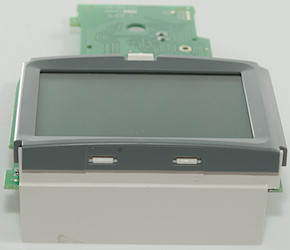
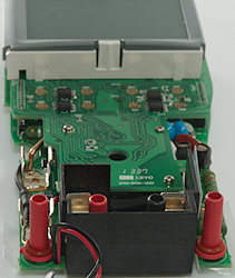
I had to remove two screws to remove the display, the backlight is connected with springs.
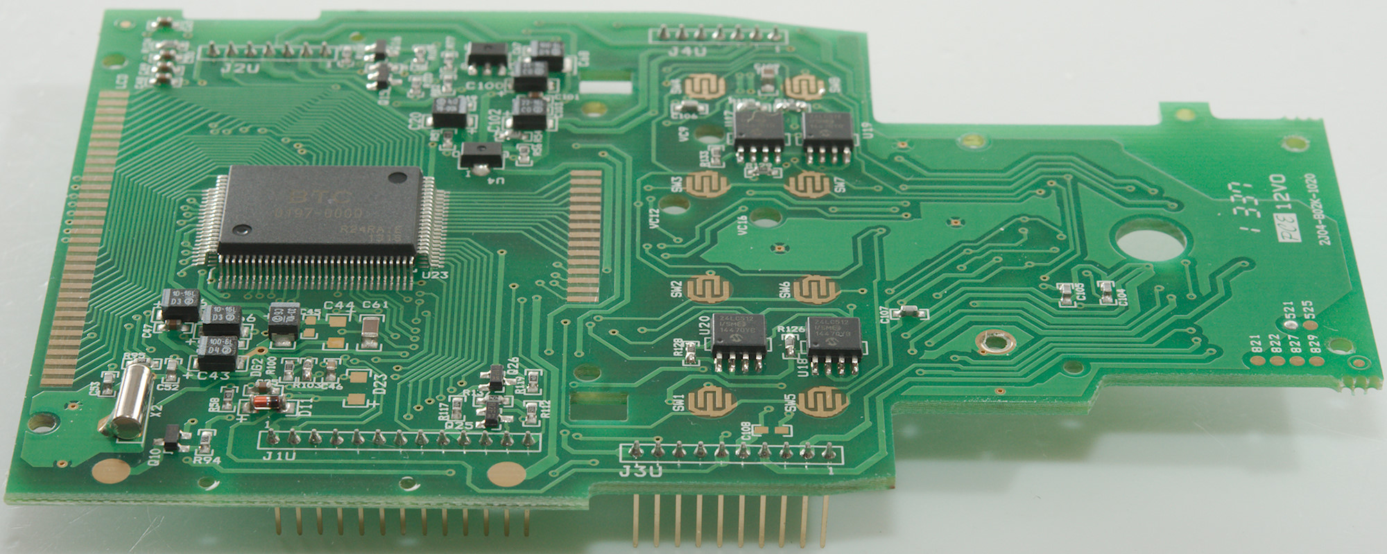
Below the display is the processor (A guess) and display driver (U23: BTC 0197-000), probably some voltage stabilization (U4 & U5).
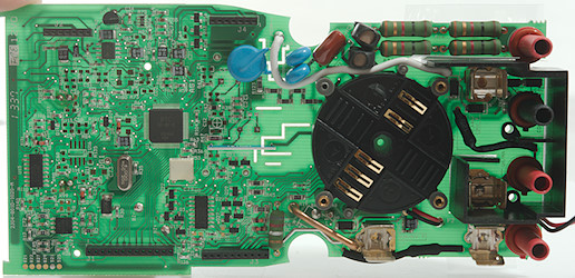
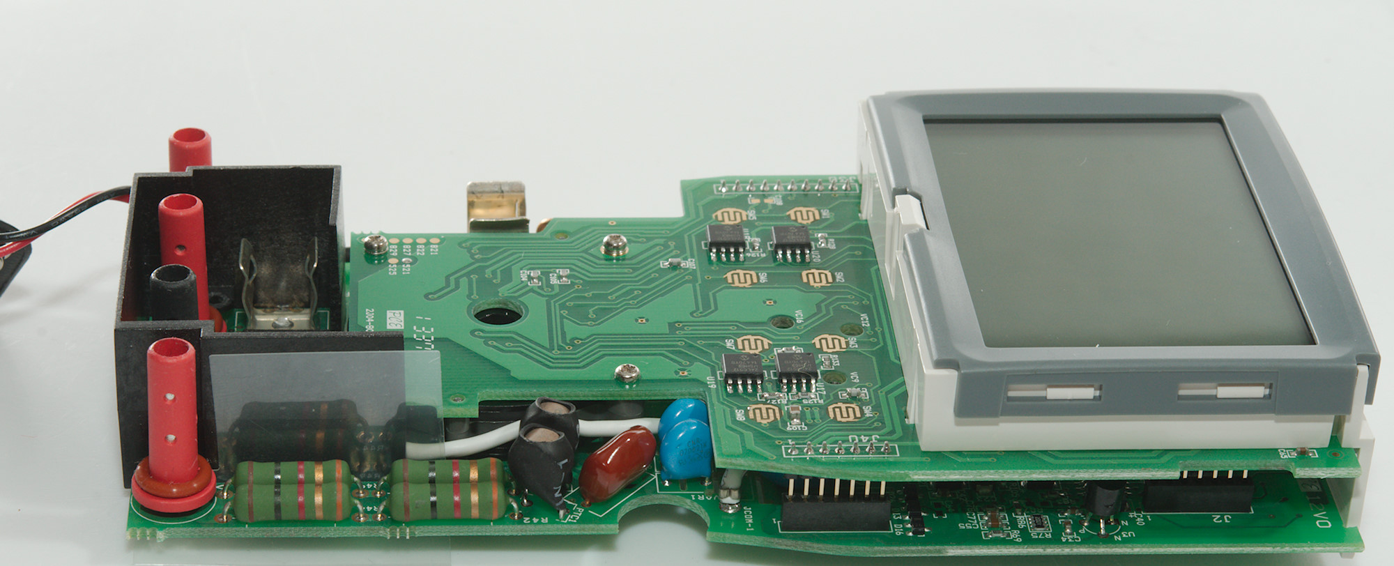
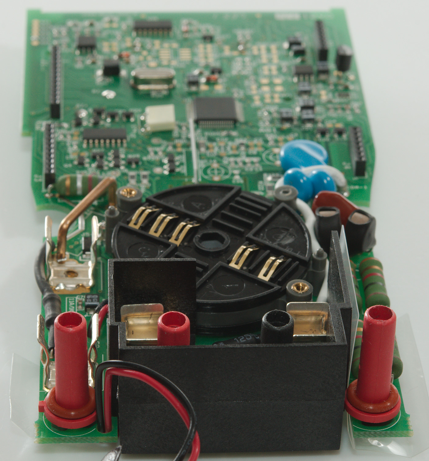
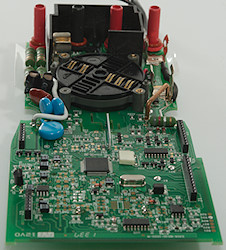
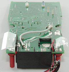
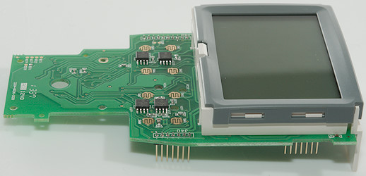
A closer look at the analog part.
Conclusion
This meter has a lot of protection and mounted the right way, it do also have very large fuses.
All the common ranges are present and also a lot of extra functions like Peak, Dual-display, AC+DC, LowZ, logging. This makes it a very universal meter with just about any desired function. The logging works nicely and the ability to save multiple sessions makes the stand alone logging really useful, but you always have to set the logging speed just before starting or just use the default.
Notes
How do I review a DMM
More DMM reviews