DMM Brymen BM829s
This is the fairly advanced Brymen meter with good precision and PC connection (Must be bought separately).
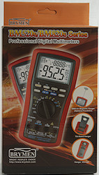
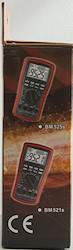
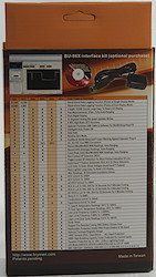
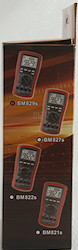
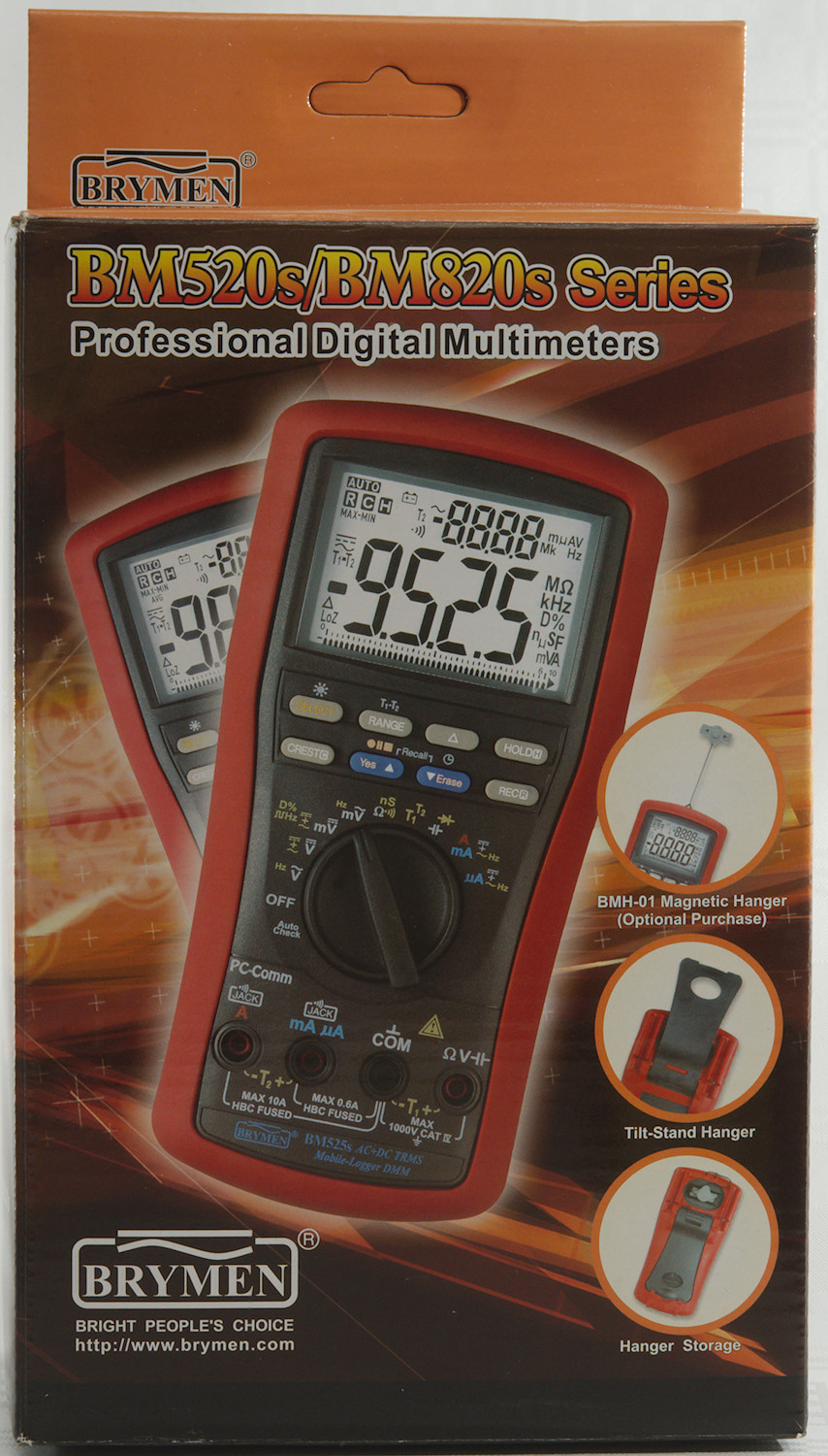
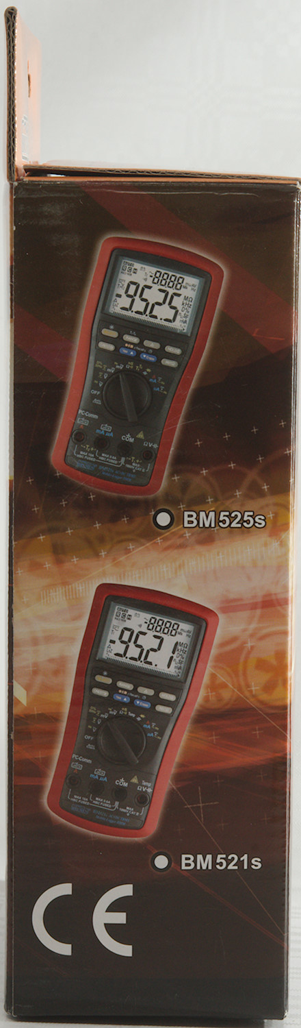
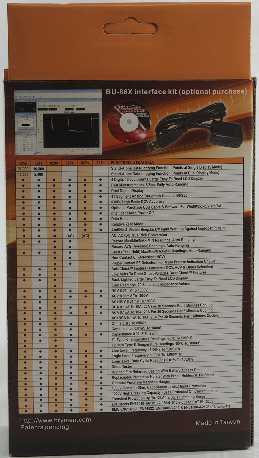
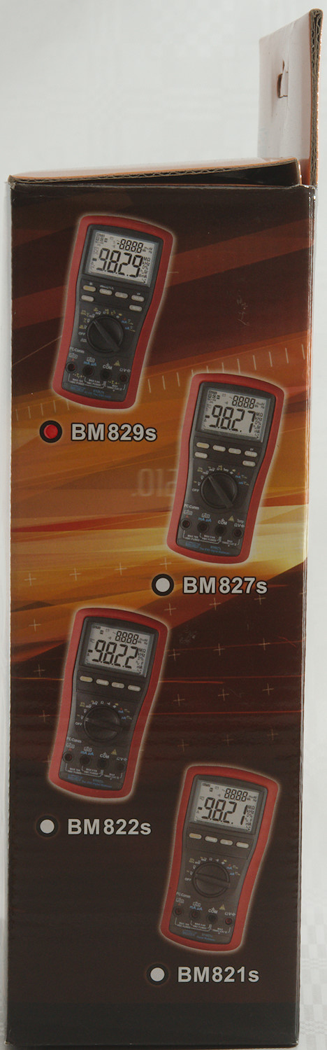
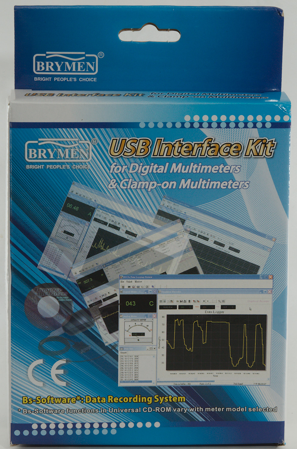
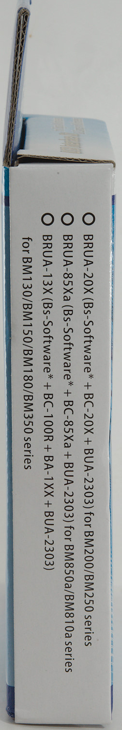
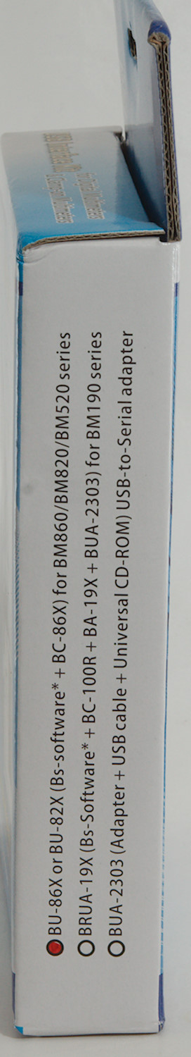
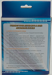
The meter arrived in a cardboard box that is used for a couple of models, on the back is a table comparing them. This meter is the most fully featured, except it is missing off-line logging.
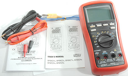
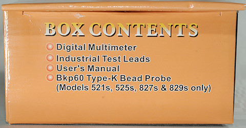
The box included the meter, two probes, a thermocoupler (Meter supports two) and the manual (It can also be downloaded).
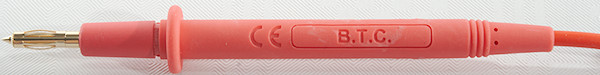
Probes are branded with B.T.C. and has removable tip covers.
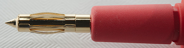
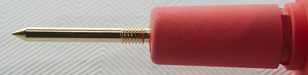
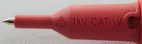
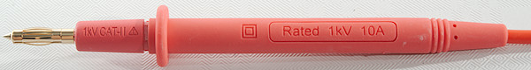
The probe-tip has different configuration, one is rated for up to CAT IV 1000V like the meter.
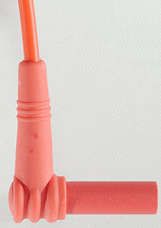
The plug is fully shrouded and standard probe plug size.
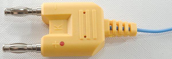

A standard thermocoupler with a standard dual banana connector.
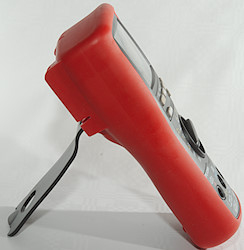
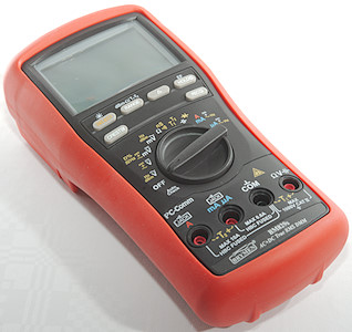
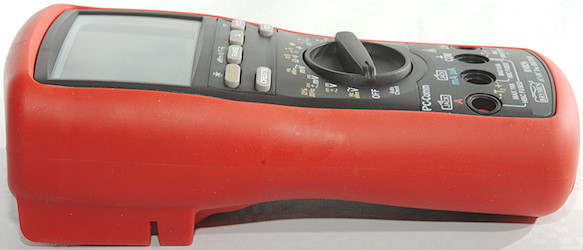
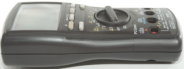
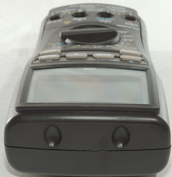
The meter is heavy and the tilting bale can hold it while the range switch is used or the buttons is pressed.
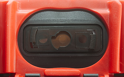
The PC connection is here with an optical link.
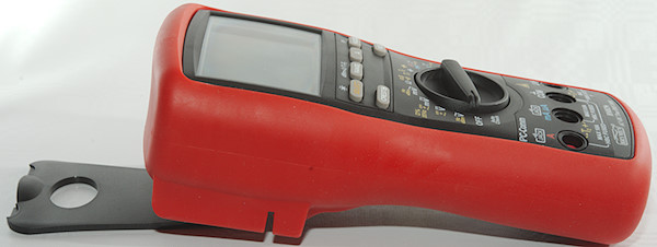
The tilting bale can be moved a bit and then be used to hang the meter on.
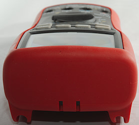
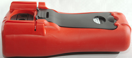
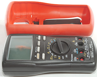
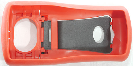
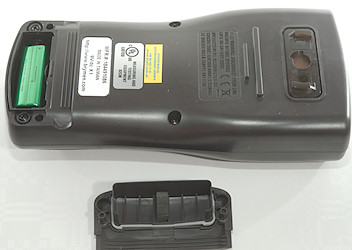
The rubber sleeve must be removed to replace the battery. There is a rubber seal around the battery cover.
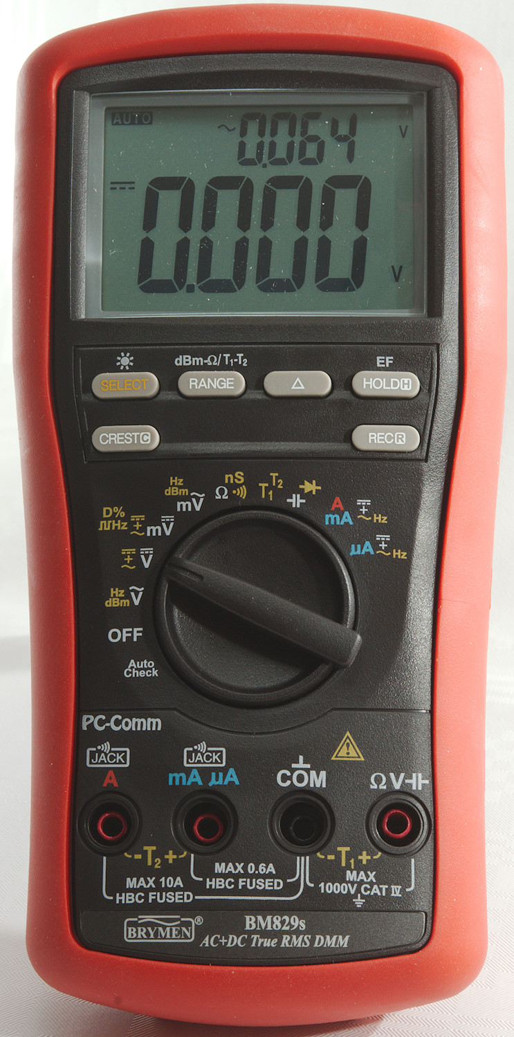
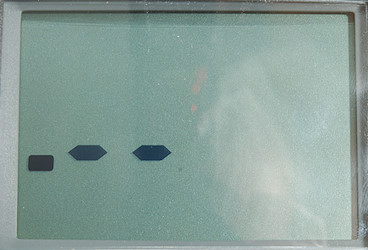
Display
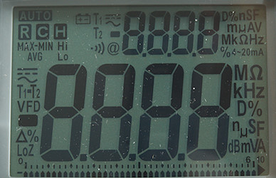
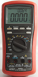
The above picture shows all the segments on the display, not all are used.
There are two 4 digit display and a bargraph. In most modes the readings goes up to 6300, but a few support 9999.
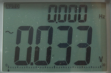
Normal AC voltage with voltage, frequency and bargraph.
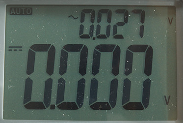
In DC volt it is possible to show both AC and DC volt, but the bargraph disappears.
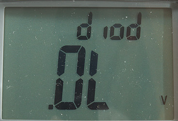
There is no diode symbol, instead the small display is used to write diode.
The NCV or Electric field mode, it can show from 1 to 5 bars
Dual and single display functions (After / is small display):
VAC: VAC/Hz, dBm/Hz, Hz/VAC
VDC: VDC, VDC/VAC, DC+AC/VAC
mVDC: mVDC, mVDC/mVAC, mVDC+mVAC/mVAC, Hz, Duty Cycle
mVAC: mVAC/Hz, dBm/Hz, Hz/mVAC
Temp: T1, T2, T1/T2, T1-T2/T2 (Use RANGE to select)
uA, mA, A: ADC, ADC/AAC, ADC+AAC/AAC, AAC/Hz
Functions
Buttons (Range selection and a few other are remembered):
- Select (Yellow): Select between the different modes on each position of the range switch, hold down to activate background light. Meter will remember the selection and use it next time the range is selected.
- Range: Switch to manual range and select range, hold down to activate automatic ranging again. In dB mode this button will select reference impedance from 20 different values, in temperature mode it will select different combinations of thermocouplers.
 : Shows values relative to current value.
- Hold: Freeze the display, press again to release. Hold down to select NCV or electric field mode, the range switch is ignored.
- Crest: Peak mode, will record and show fast min/max. Use button to change between min/max/max-min. Hold down to end mode.
- Rec: Minimum/maximum mode, will record min/max values. Use button to change between actual/max/min/max-min/average. Hold down to end mode.
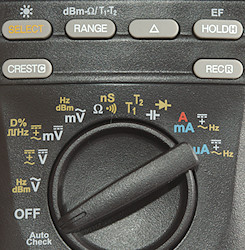
Rotary switch:
- Auto: Meter will automatic select between ohm, continuity, VAC, VDC with LowZ on voltage ranges.
- Off: Meter is turned off.
- VAC: Measure AC voltage, frequency and dB
- VDC: Measure DC voltage, AC voltage and AC+DC voltage.
- mVDC: Millivolt range, measure DC voltage, AC voltage, AC+DC voltage, frequency and duty cycle.
- mVAC: Millivolt range, measure AC voltage, frequency and dB
 : Resistance and continuity, the nS makes it possible to measure very huge resistance
 - T1 T2: Measure temperature with one or two thermocouplers, can also show difference between them.
 : Capacitance and diode range.
values.
- A mA: This is either mA or A depending on where the probe is connected. It will measure DCA, ACA, ACA+DCA, frequency
- uA: The uA range. It will measure DCA, ACA, ACA+DCA and frequency.
dB reference impedance: 4, 8, 16, 32, 50, 75, 93, 110, 125, 135, 150, 200, 250, 300, 500, 600, 800, 900, 1000, 1200
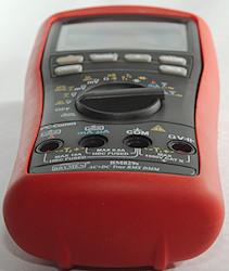
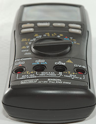
Input
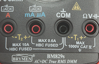
- A: High current, maximum current is 10A, also ground for second thermocoupler.
- mAuA: The lower current ranges and + input for the second thermocoupler.
- CON: The common terminal for all ranges.
- xxx: All other ranges.
Measurements
- Volt and frequency
- Frequency input (mVDC) has a trigger point around 1.2V
- At 1Vrms frequency input (mVDC) range is from 2Hz to 180kHz
- At 5Vrms frequency input (mVDC) range is from 2Hz to 3.3MHz
- Frequency input (mVAC) requires a zero crossing
- At 100mVrms input on mVAC range, frequency range is from 2Hz to 65kHz
- Frequency input (VAC) do not require a zero crossing, it is AC coupled.
- At 1Vrms input on VAC range, frequency range is from 2Hz to 29kHz
- Duty cycle works from 5% to 99% at 100kHz with 4Vpp, precision is within 3.5
- Duty cycle works from 1% to 99% at 10kHz with 4Vpp, precision is within 0.4
- 1 VAC is 5% down at 7kHz (RMS will not work at the frequency).
- 0.5 VAC in mVAC is 5% up at 16kHz (RMS will not work at the frequency).
- Auto range works when doing min/max, peak and relative.
- Auto input has just below 1V out to detect a resistor, it will switch to VDC at 1.2VDC input or VAC at 0.6VAC input.
- Max/min (Rec) needs about 570ms to capture a voltage, it may use multiple captures to get the final value.
- Peak (Creast) needs about 0.7ms to capture a DC voltage, it may use multiple captures to get the final value.
- Input impedance is 10-11Mohm on DC
- VAC input has a capacitor and is 10Mohm after that.
- mV DC/AC has 10Mohm input impedance up to about 3.5V, then it drops to 20kohm at 10 volt and 4kOhm at 35 volt.
- Frequency input is similar to mV
- Rated overload protection on V ranges is 1050VDC/VAC and 12kV transient.
- Rated overload protection is 600VDC/VAC and 12kV transient in mV range.
- Current
- Overload protection in uA and mA: 0.44A/1000V 10x38mm fuse
- Overload protection in A: 11A/1000V 10x38mm fuse
- There is an audible warning and display shows "InEr" when using non current ranges with a probe in mAuA or A input.
- Ohm, continuity, diode and capacitance
- Ohm needs about 1.9s to measure 100ohm
- Ohm is 1.0V open and 0.17mA shorted
- Continuity is very fast (Below 5ms).
- Continuity beeps when resistance is below 220ohm
- Continuity is 1.2V open and 0.17mA shorted
- Conductivity (nS) is 1.2V open and 0.3uA shorted
- In conductivity it is best to keep some distance to the meter.
- Diode range uses 3.1V, max. display is 2.000V at 0.14mA, max. current is 0.38mA shorted
- 10uF takes about 2.8 seconds to measure.
- 11000uF takes about 9.5 seconds to measure, it shows a wrong value first.
- Rated overload protection is 600VDC/VAC and 12kV transient.
- Miscellaneous
- Current consumption of meter is 4mA-5mA (35mA with backlight)
- Meter works down to 4.0V where it says "InEr", battery symbol show at 6.7V.
- The meter reading is stable down to 5.6V, then it will show too high value (It was 36% to high at 4V).
- Backlight is stable until meter reports "InEr".
- The meter sometimes need a couple of updates before the reading is fully correct.
- Viewing angle is good
- Display updates around 5 times/sec.
- Bargraph updates 60 times/sec
- Backlight will turn off in 30 seconds
- Will automatic turn power off in about 30 minutes without any warning.
- Standard probes fits perfectly into sockets on meter.
- Weight is 630g without accessories, with sleeve and battery.
- Size is 208 x 102 x 64mm.
- Probes
- Probe resistance 30mOhm for one.
- Probe wire is soft and 100cm long.
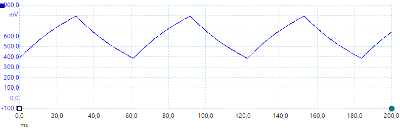
A look at the capacitance measurement waveform.
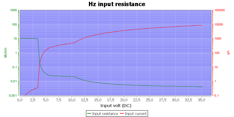
Frequency input resistance, this is similar to mV

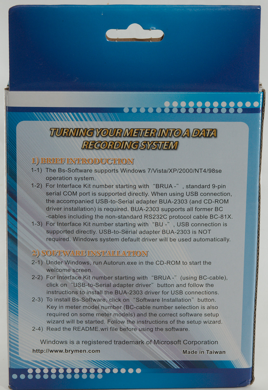
Software
The software must be bought separately.
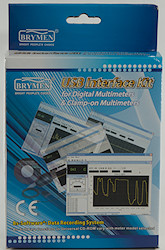
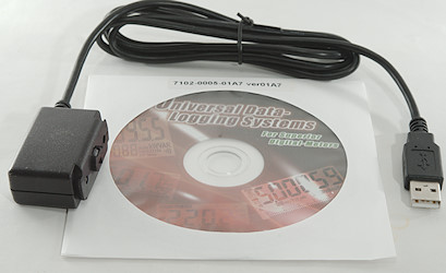
The box only includes a cable and a CD. The CD contains software for many different meters and also files describing the data format (It is the display segments, not digits that is transmitted). The software can be downloaded directly from Brymen without any problems, this is what I did for this meter.
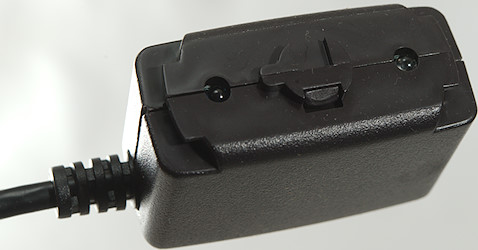
The opto adapter has two leds and some mechanic to lock it securely in place.
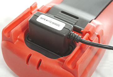
Here it is mounted on the meter.
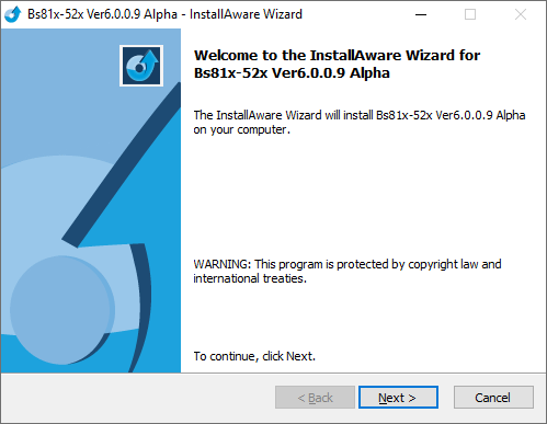
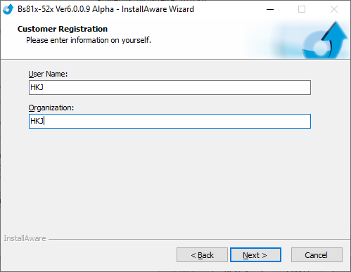
I downloaded the software from Brymen and it says it is a alpha version, the program inside the ZIP file has a file data from 2012.
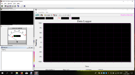
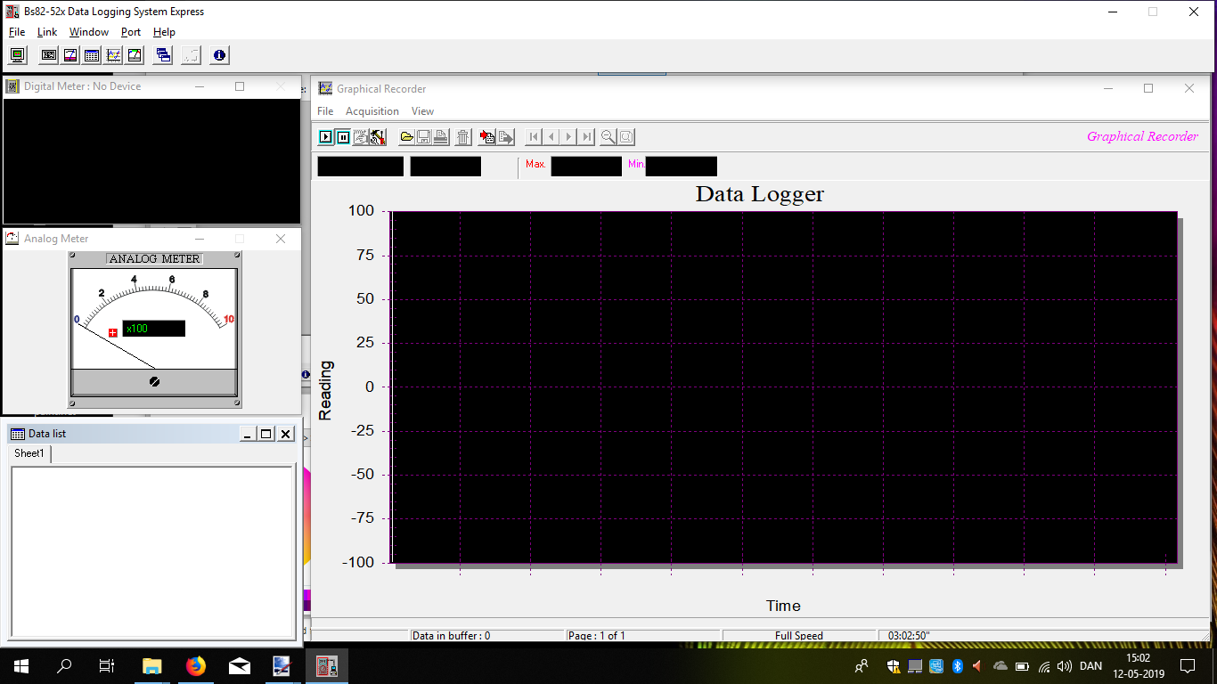
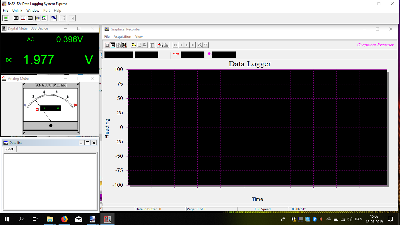
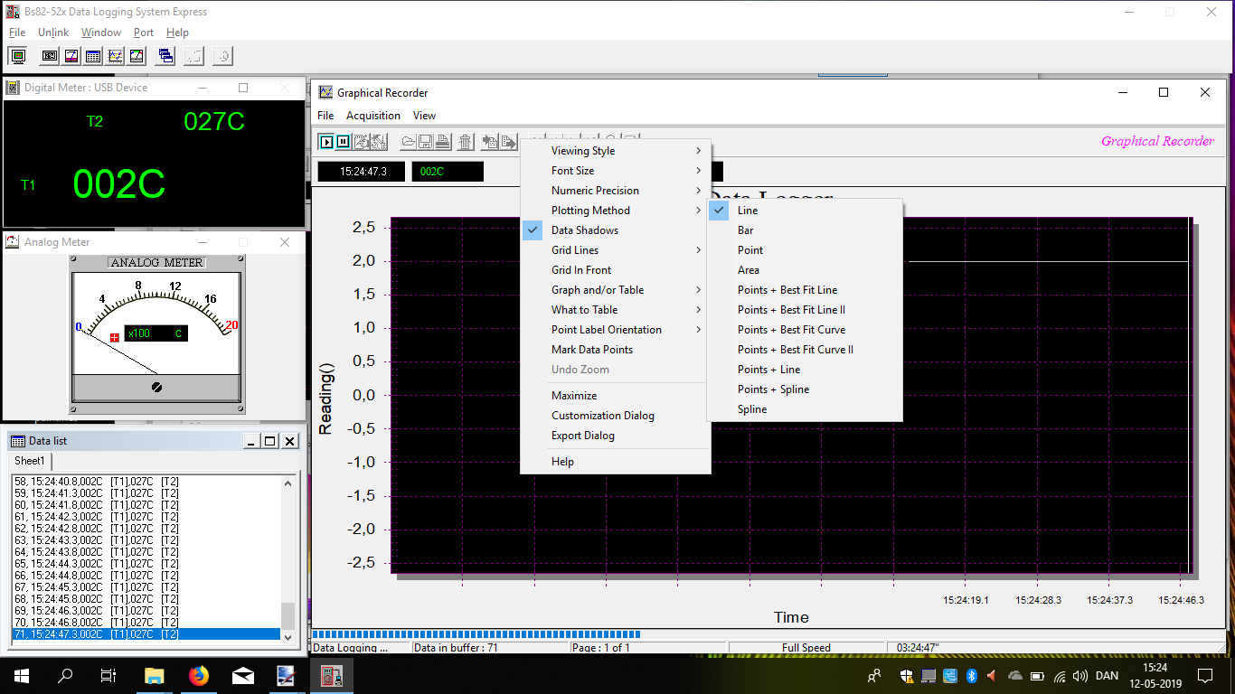
When started the program is a couple of windows, they can be opened and closed separately. The table and chart view can be resized.
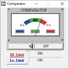
There is one more window available.
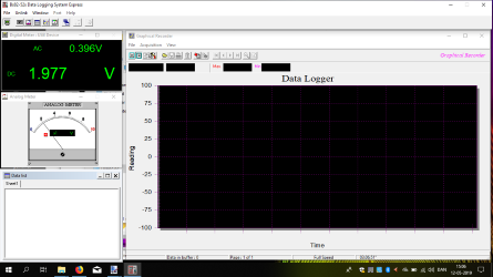
Pressing the connect button shows one or two values from the meter, but there is no special support for min/max/peak functions, it will show the same value as the display, but no indicator.
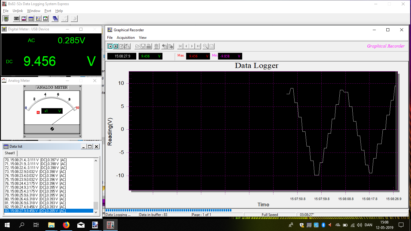
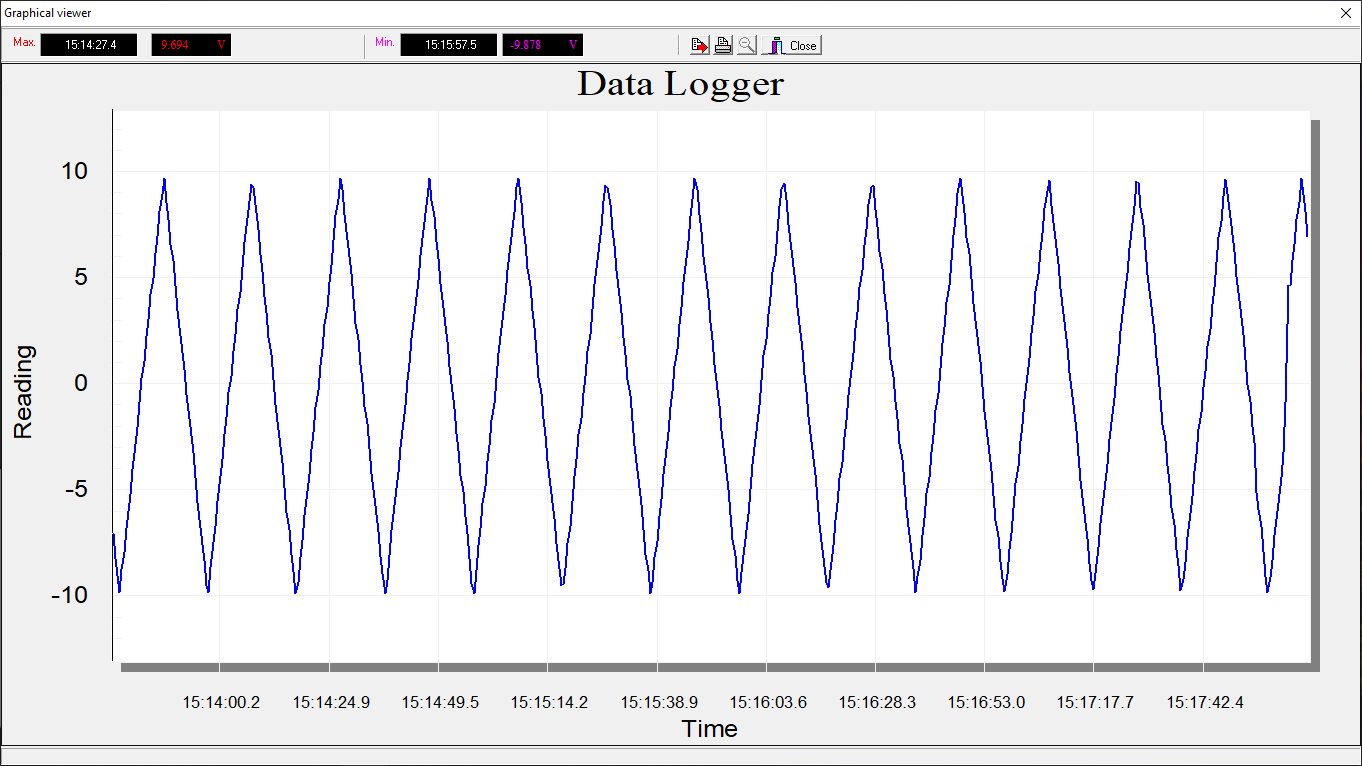
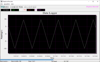
Starting record will update the chart and the table. The chart will only show the main value and the scale will depend on the currently selected range.
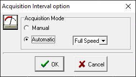
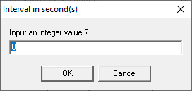
It is possible to adjust the sample interval.
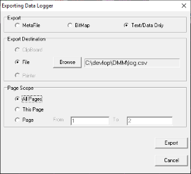
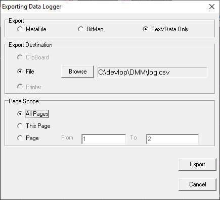
And export the data.
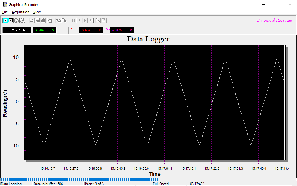
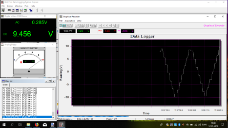
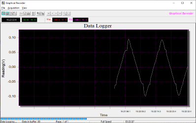
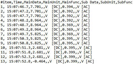
Here I did a chart where I only logged DC volt, the update is faster than above where I logged AC and DC volt.

The standard chart window will only show a fixed amount of data, but when acquisition is stopped it is possible to show all sample points in on chart (Still only one value).
Here the meter has to change between the two mV ranges while logging, it delays the data a bit, but the curve is scaled correctly.
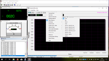
It is possible to play with design of the chart.
The saved data contains both values from the display and is in a US CSV format.
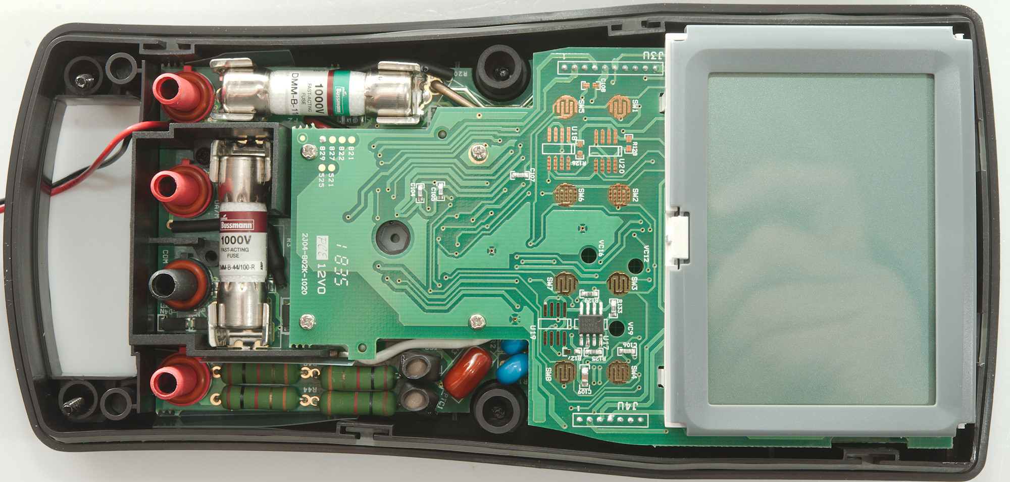
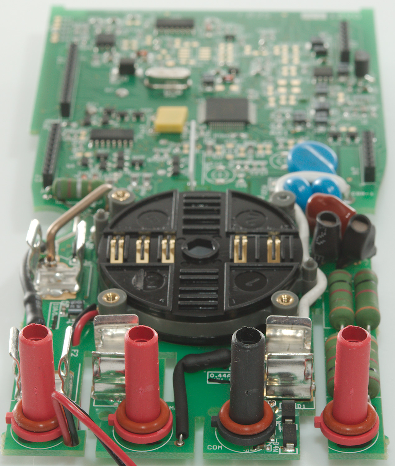
Tear down
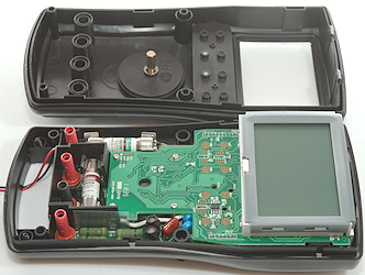
I had to unscrew four screws in addition to the battery cover to open the meter, they are captive and stays in the back.
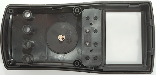
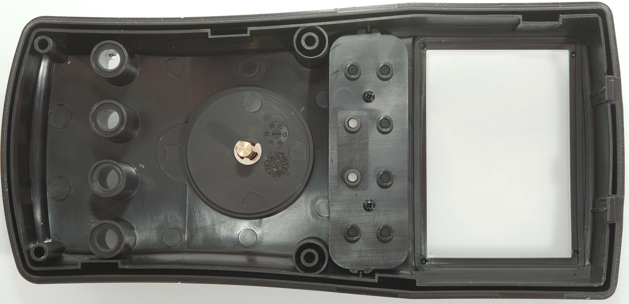
On this meter the front is removed, the range switch is connected with a metal pin.
Fuse replacement requires to open the meter.
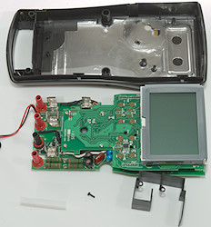
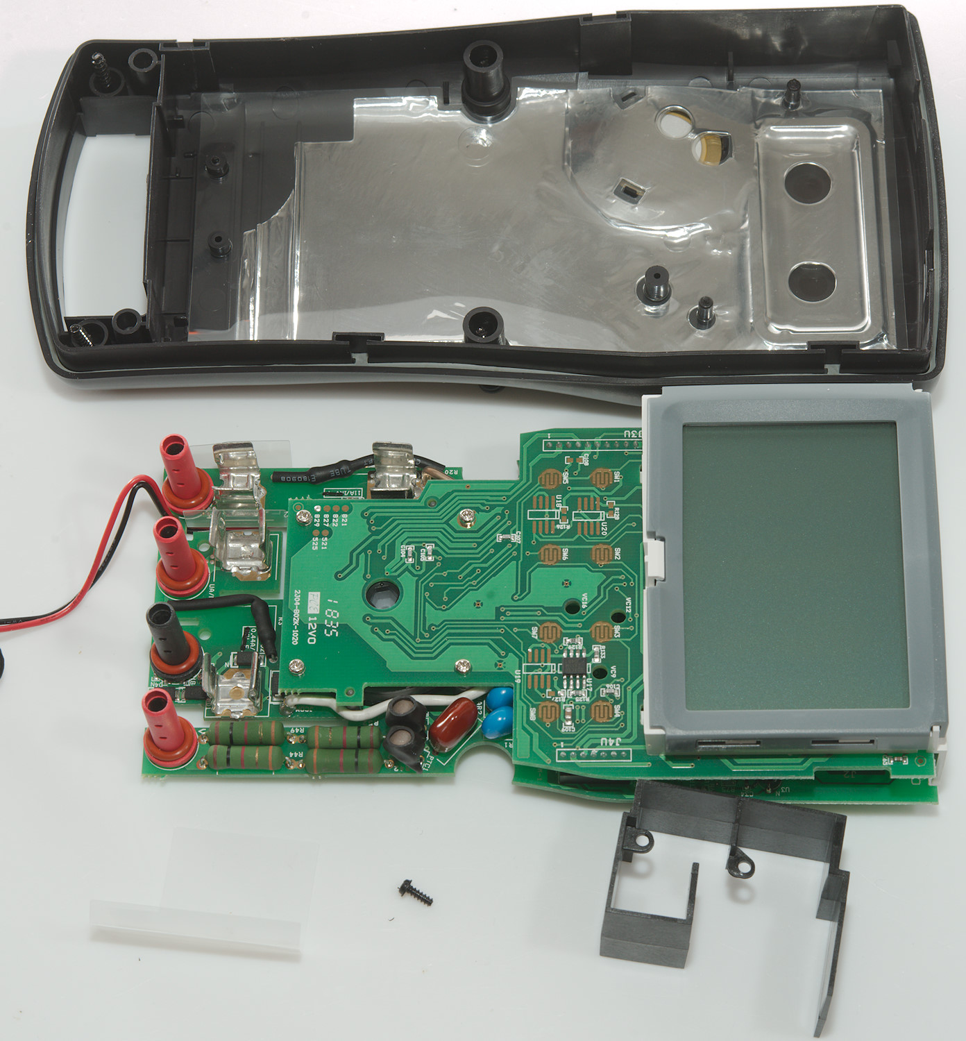
One screw more and the electronic could be removed. There is a couple of shields around the input terminals.

Here all 3 shields can be seen, one in black plastic and two in thin nearly transparent plastic. The missing screw is standard for Brymen (It is missing on all the similar Brymen I have tested), only one screw is needed to hold the circuit board in place.
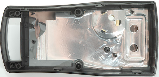
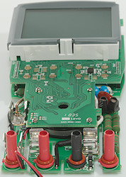
The back of the meter has a shield with holes for the buzzer and the IR communication.
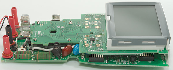
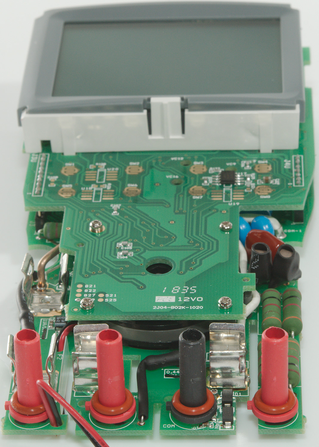
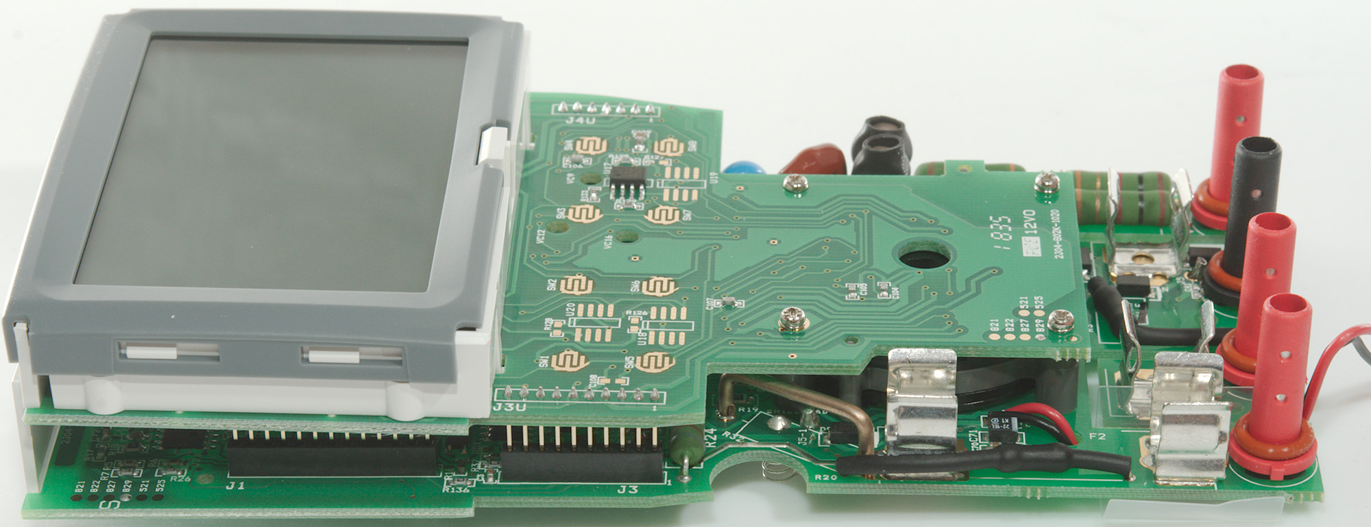
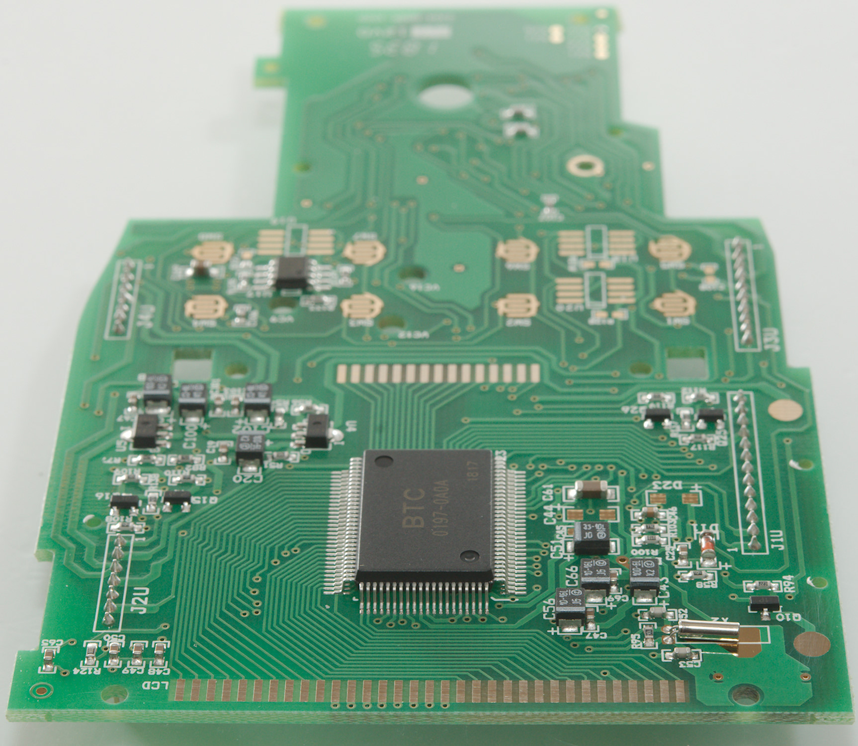
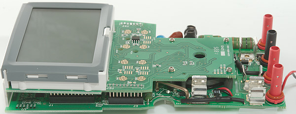
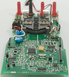
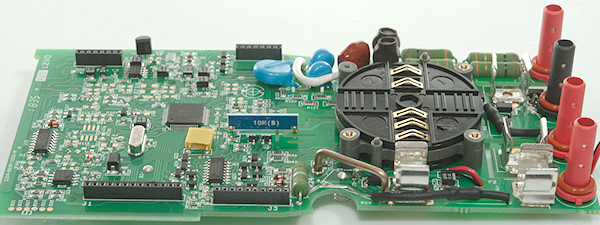
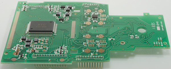
The meter uses two stacked circuit boards.
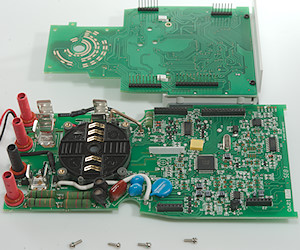
I had to remove four small screws to take the two circuit boards apart.
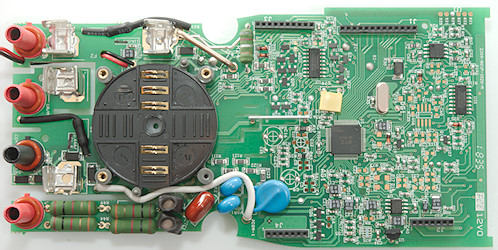
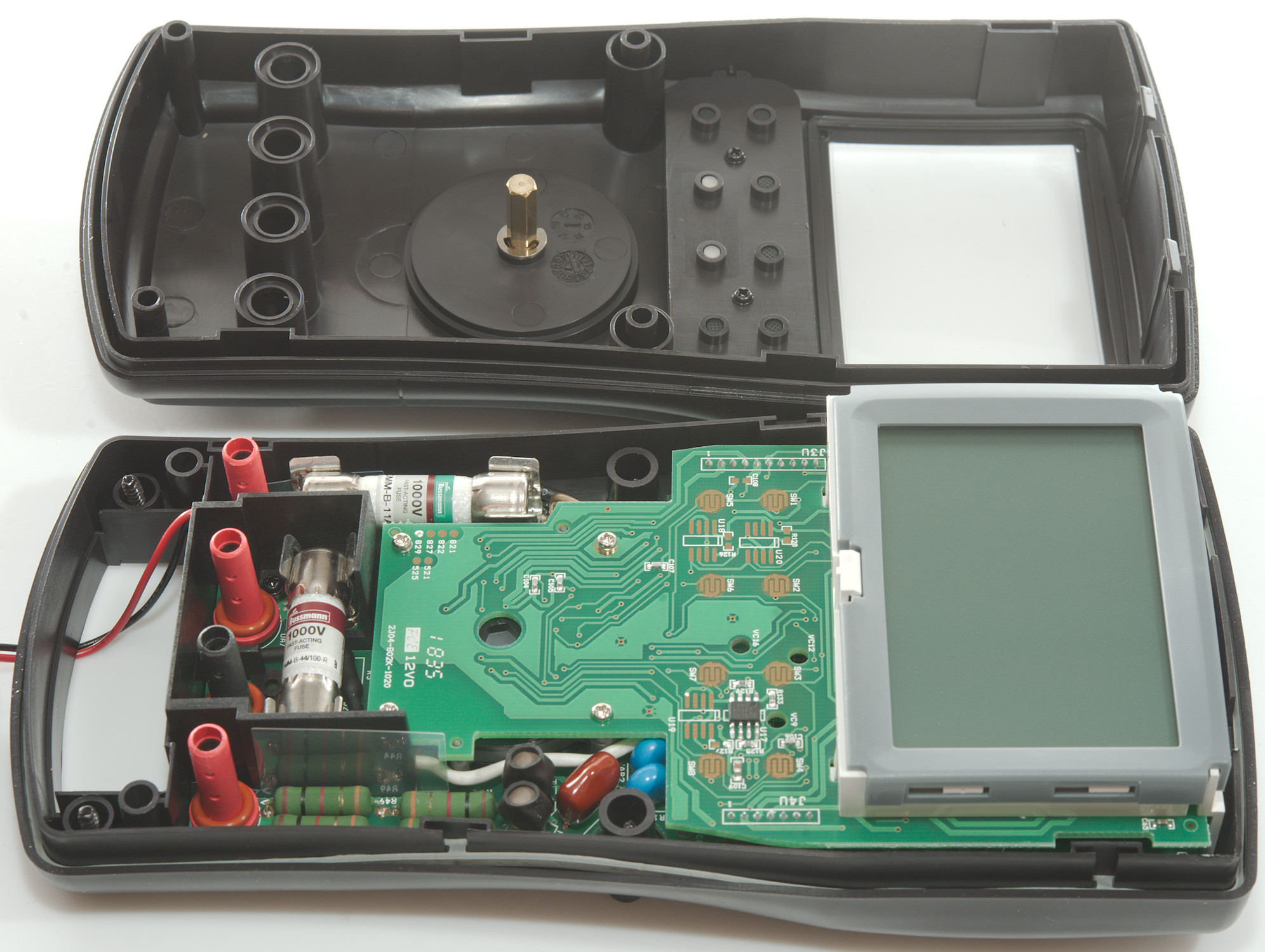
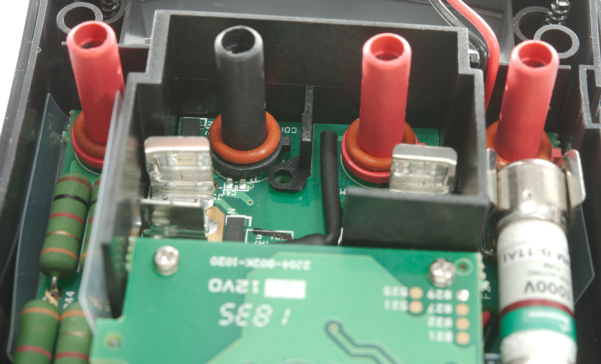
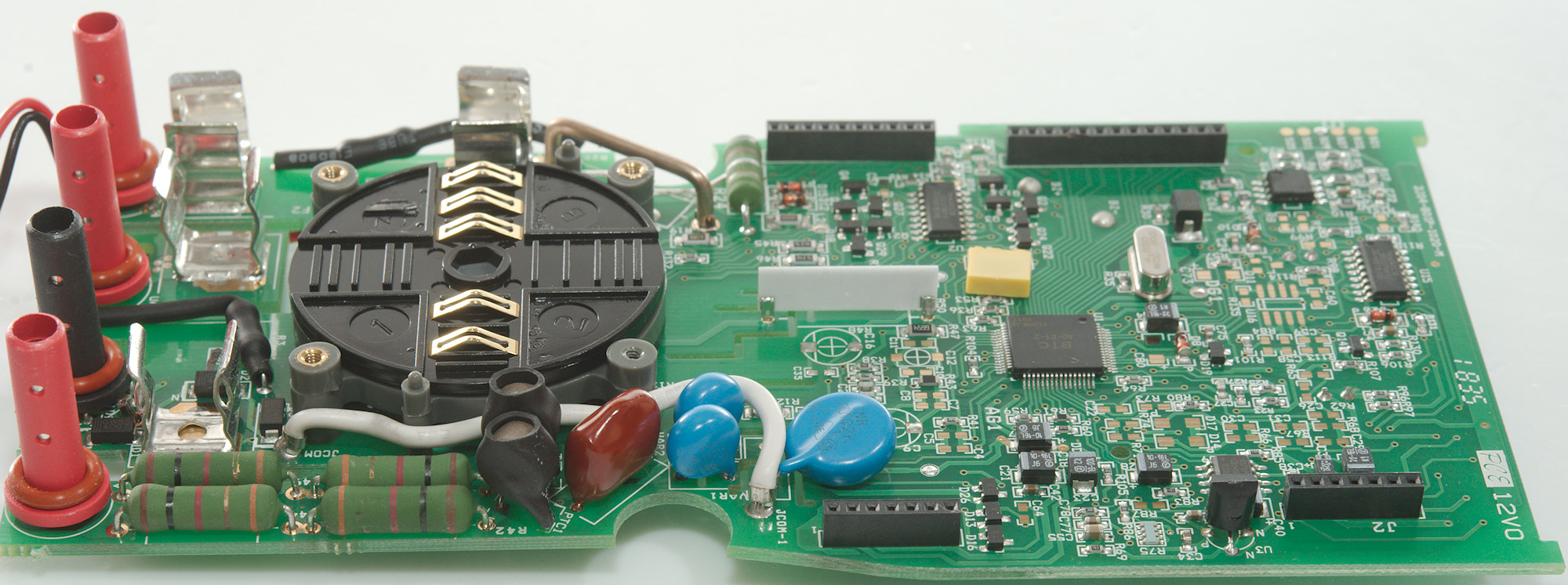
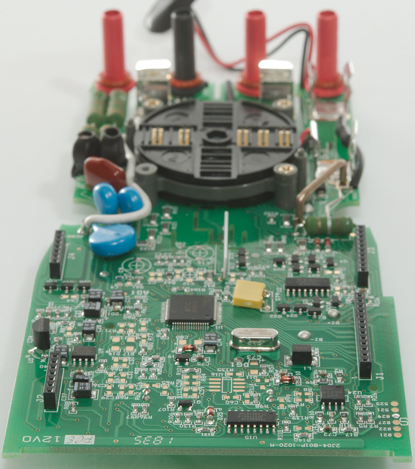
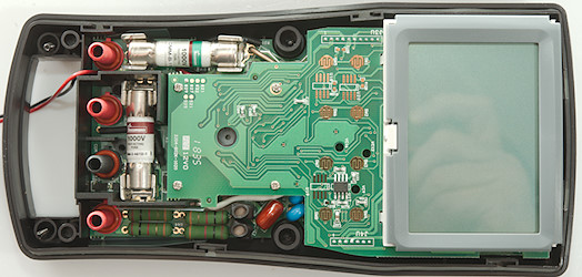
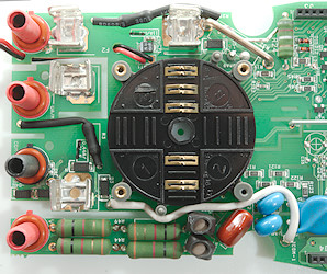
The current input terminals a switch to sense when used, they are routed with resistors (R3 & R20: 10MOhm) in shrink wrap. The current sense shunts are place above the 11A fuse, there is the usual wire shunt (R32), a leaded resistor (R24: 0.82ohm) for mA and a SMD (R19: 85ohm) for uA. The diode (D1, D2, D3, D4) protection is placed near the uAmA GND input terminal and the mA fuse.
The voltage input has two paths, both with resistor (R42, R44, R49, R??: 4x1kOhm) and PTC's (PTC1 & PTC2), after the PTC are MOVs (VAR1, VAR2. VAR3: 2x820V + 1x1000V). The capacitor (C13: 10nF 1000V) for AC input is also her. The input divider resistor (R48: 10MOhm) is on a ceramic plate.
There is no PTC resistor for the LowZ input, this means the meter is using one of the main input paths for that
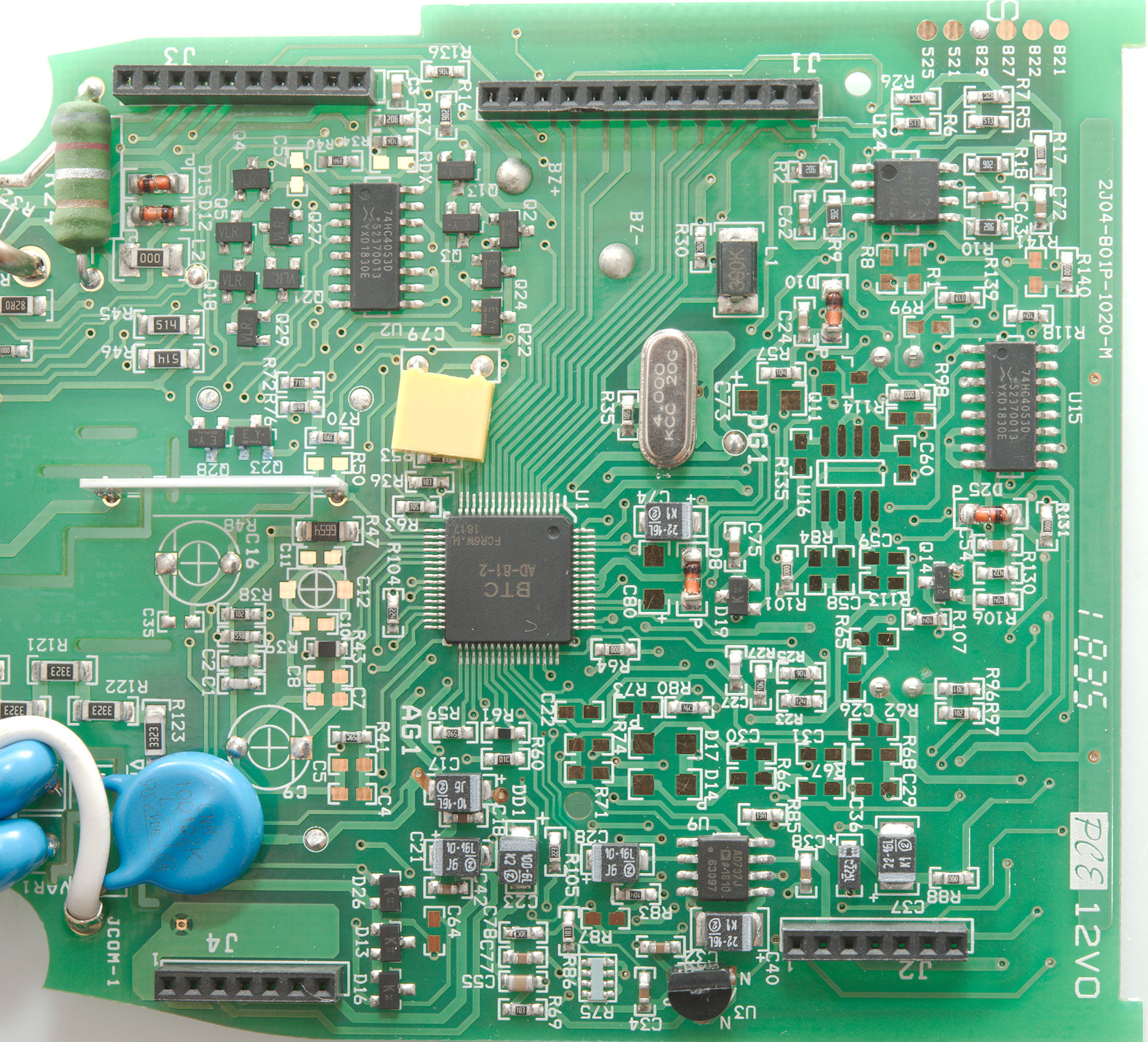
The ohm and capacitor input has a couple of transistor pairs (Q5, Q18, Q29, Q27 / Q23, Q2B / Q2, Q3, Q13 / Q22, Q24), in this case some of the "pairs" are more than two transistors.
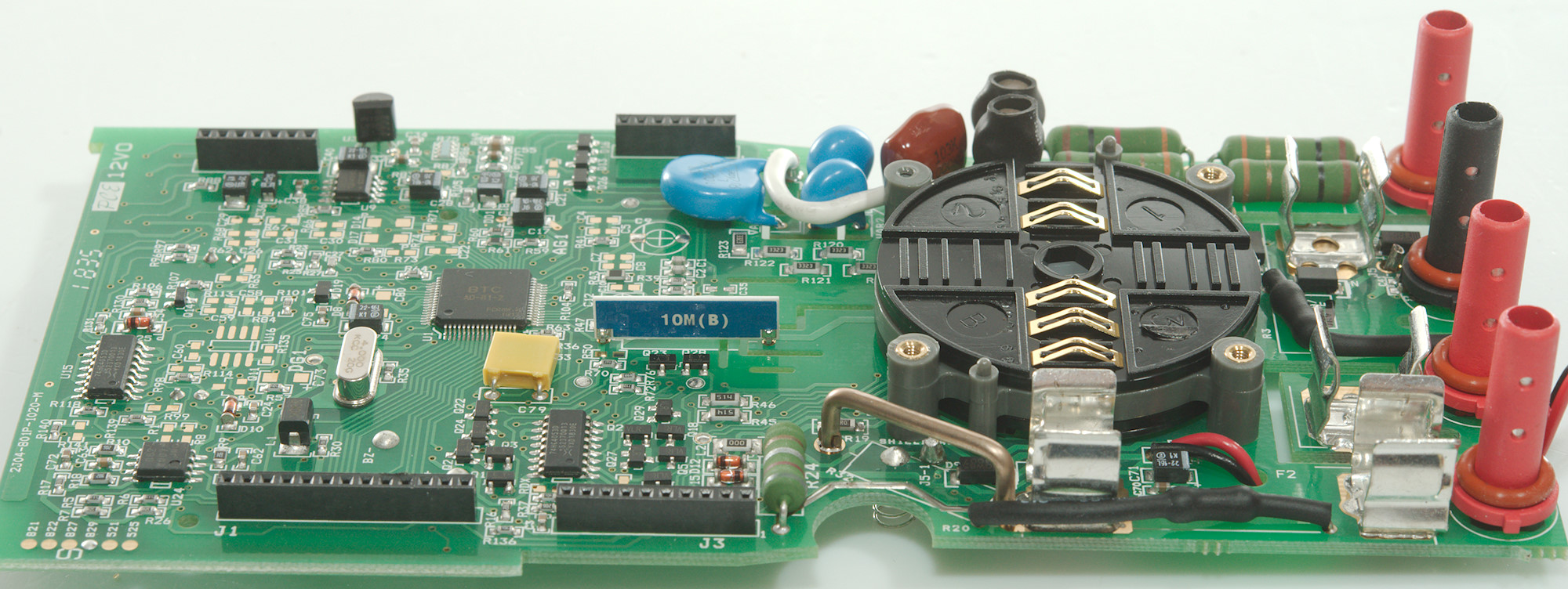
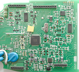
The RMS converter (U9: AD737J) is next to the reference (U3: LM385Z-1.2), the circuit has two analog muxes (U2 6 U15: 74HC4053), the ADC is probably part of the main chip (U1: BTC AD-81-2), together with lots of muxes.
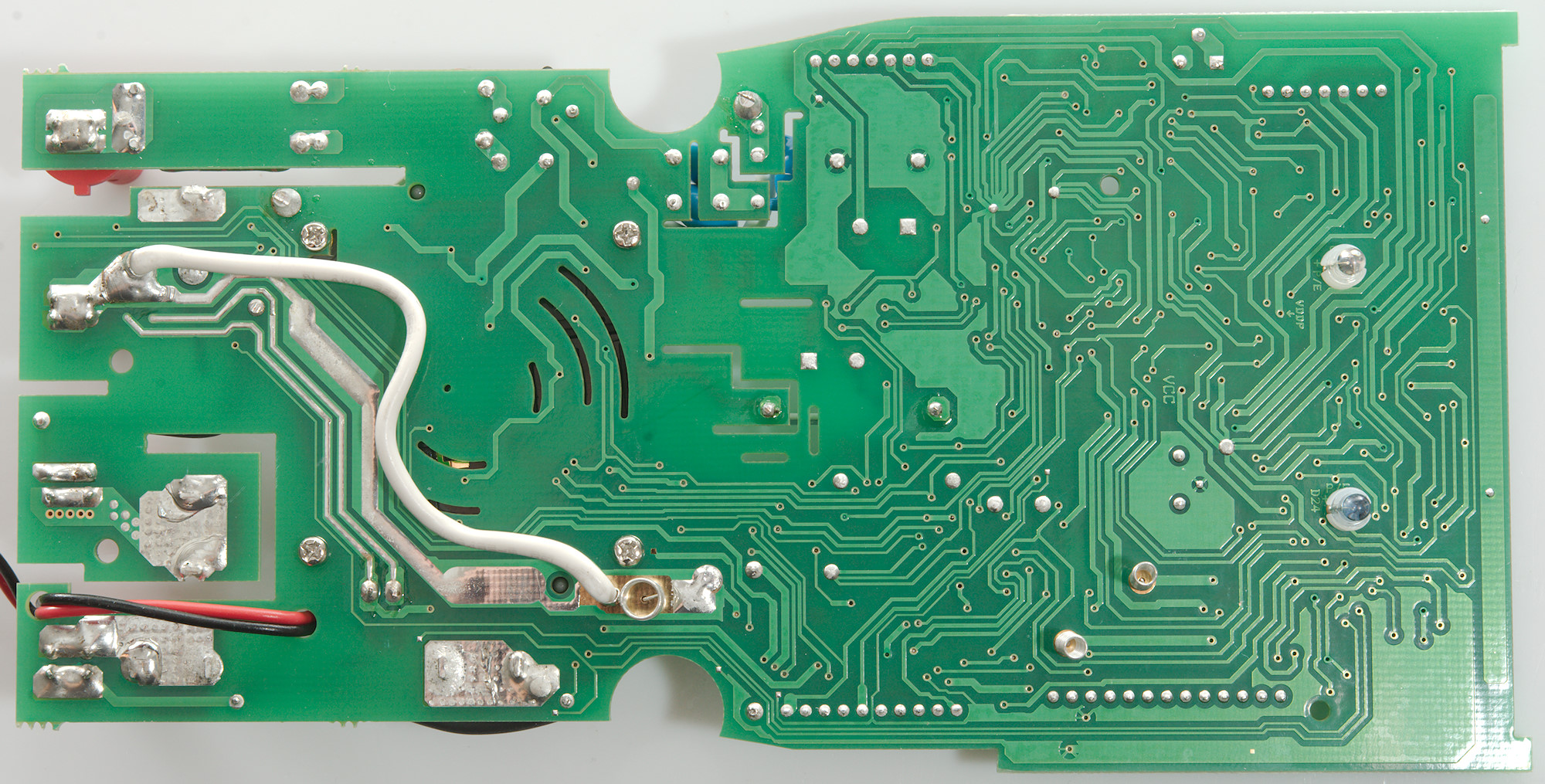
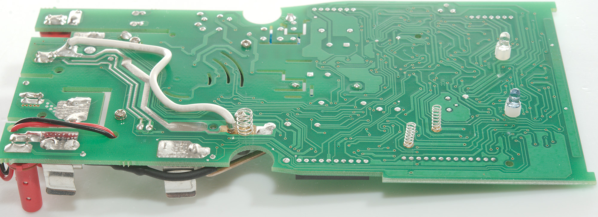
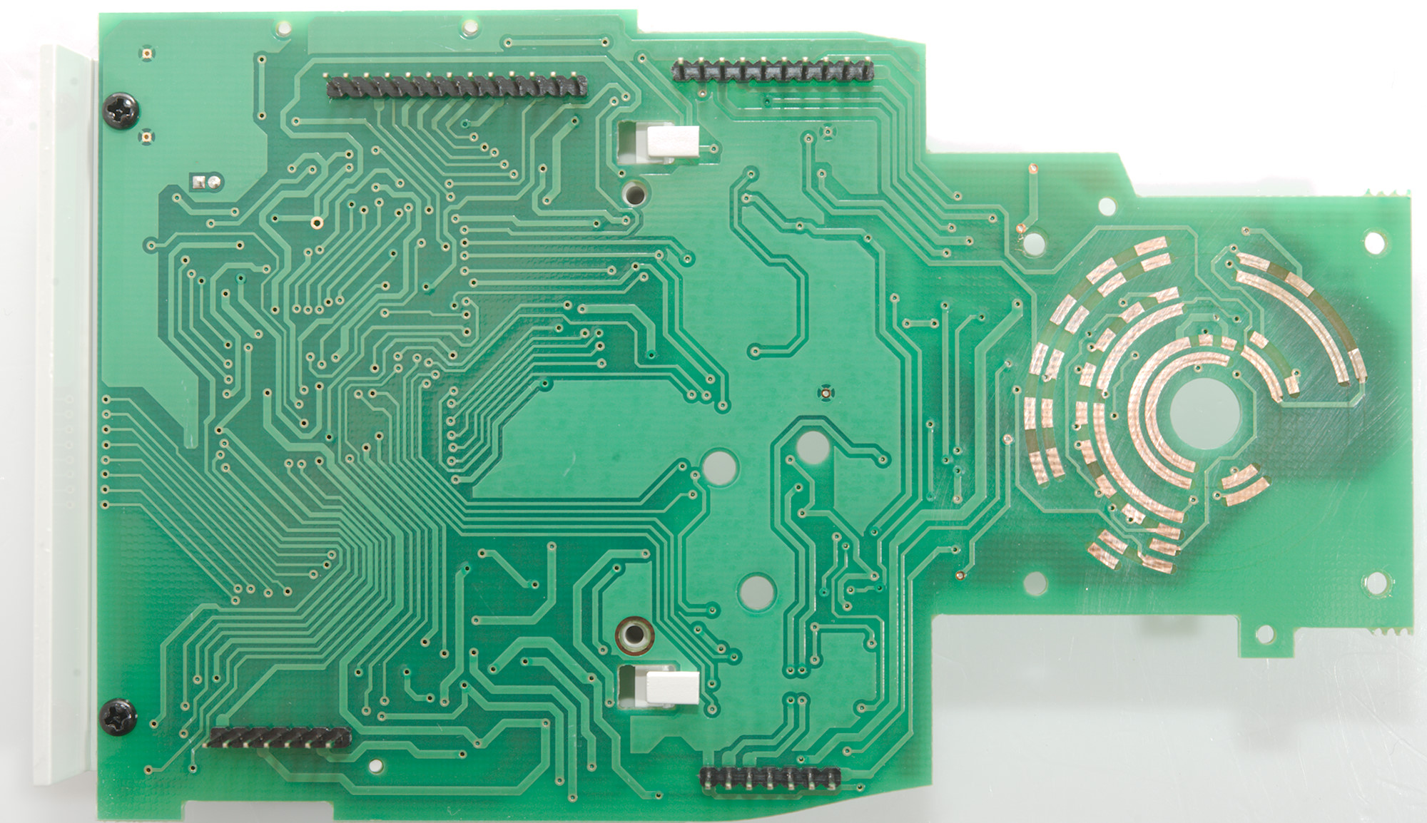
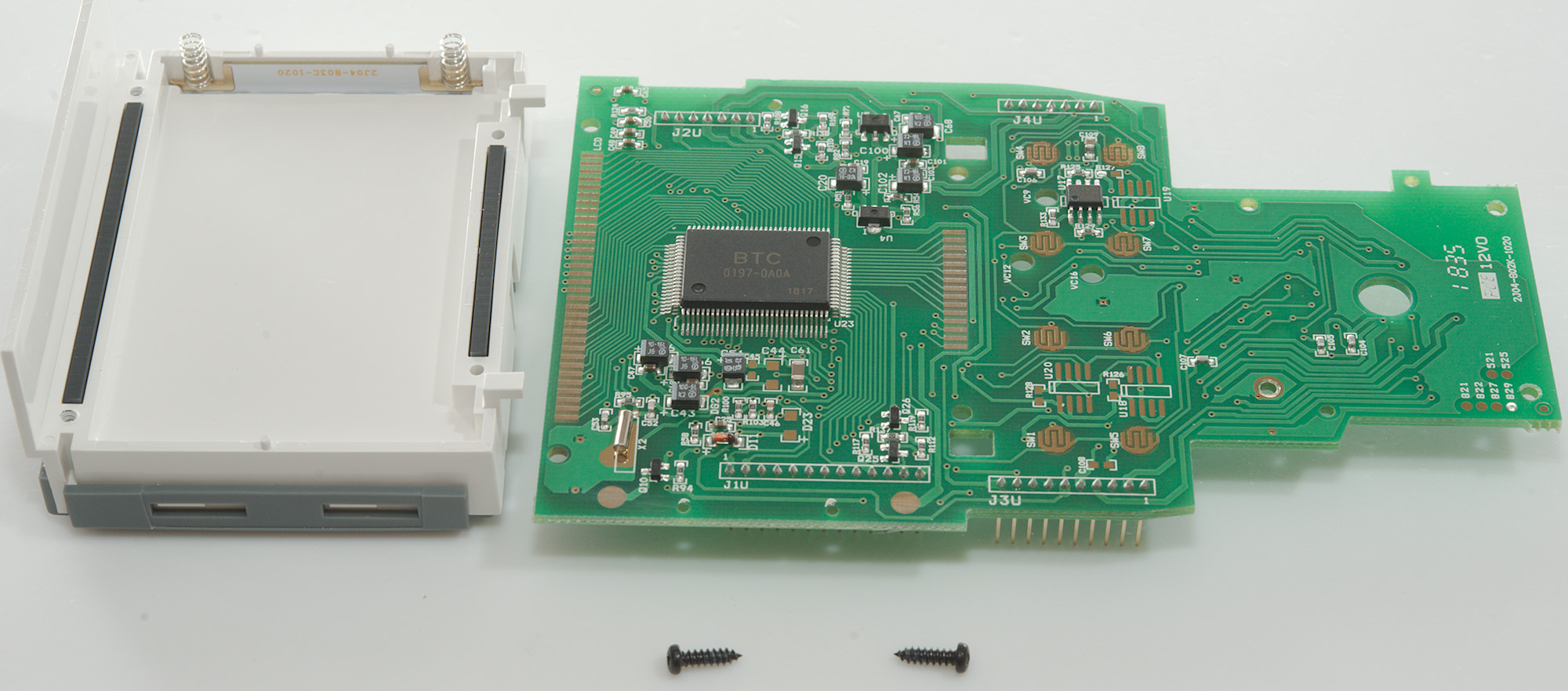
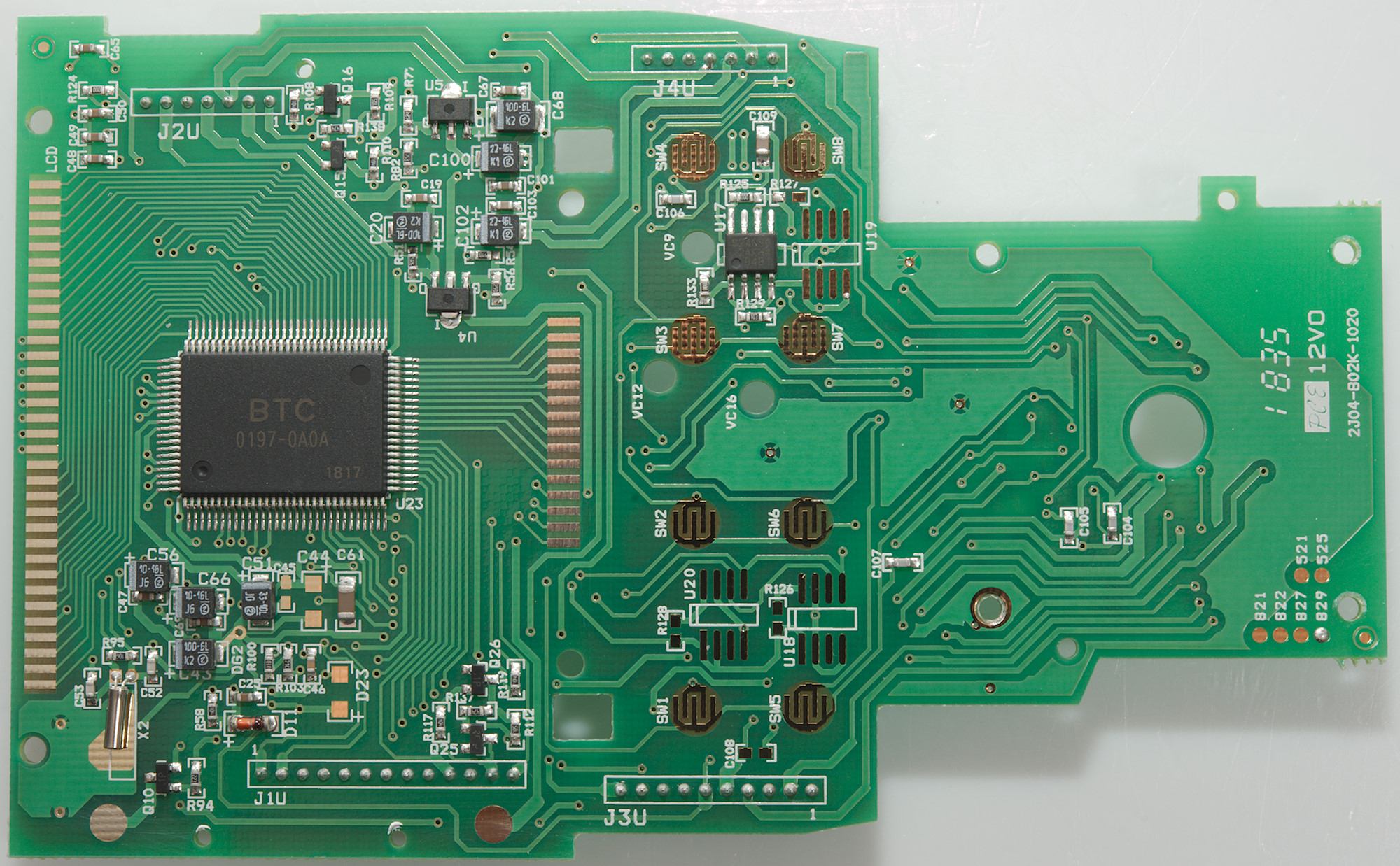
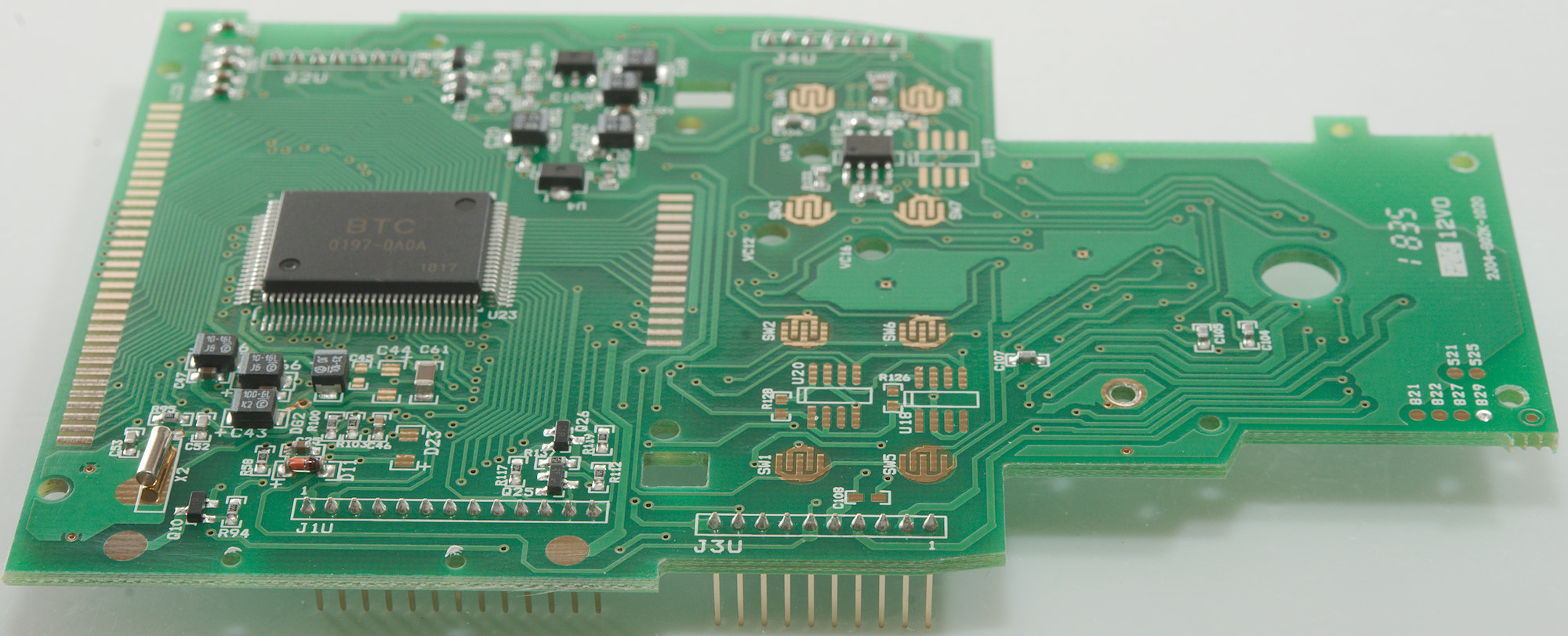
More detailed pictures.

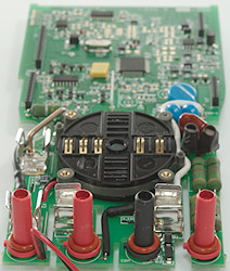
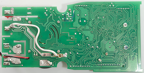
On this side is the two communication leds and springs for connecting to the buzzer and shield. Then GND (Black terminal) needed a batter connection that the circuit board and is reinforced with a wire.

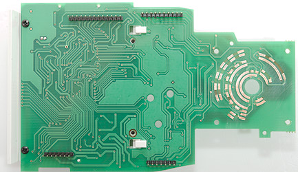
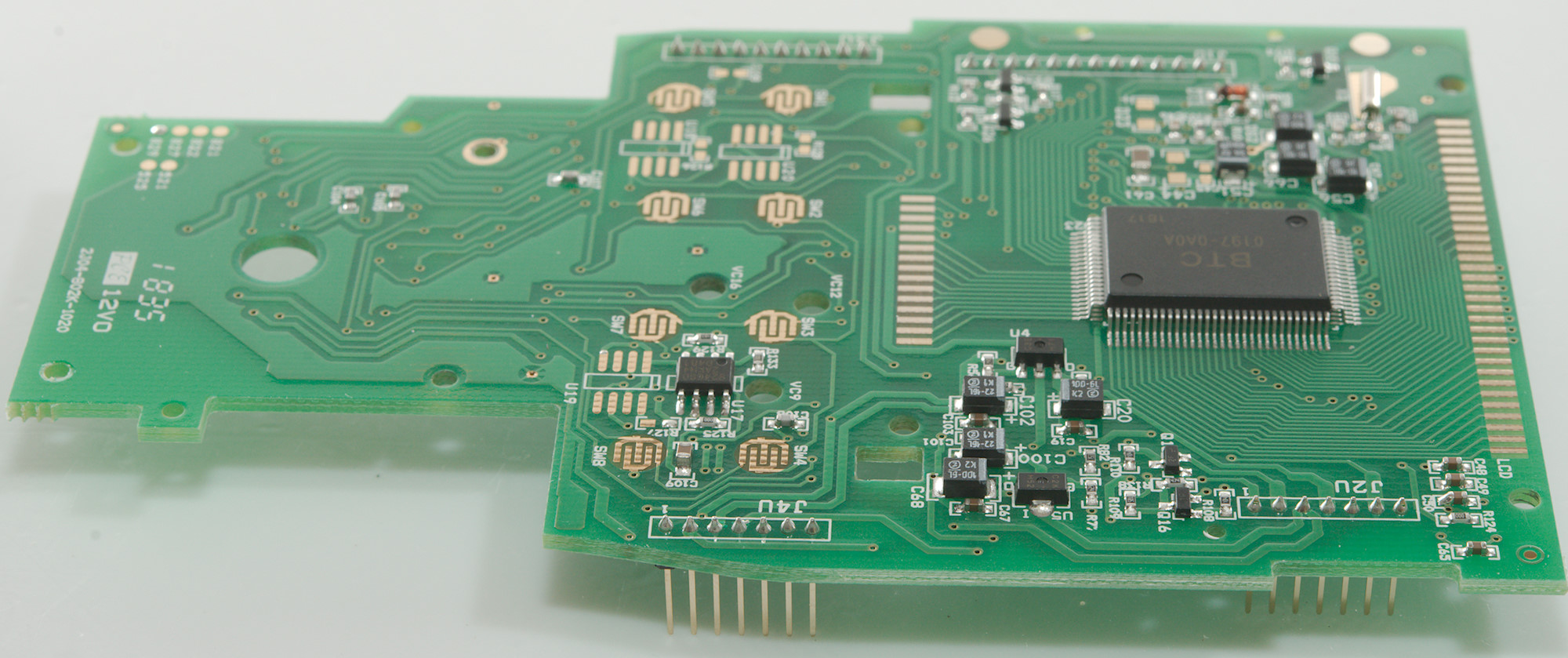
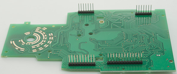
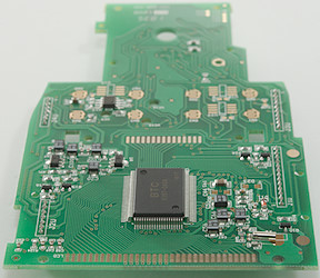
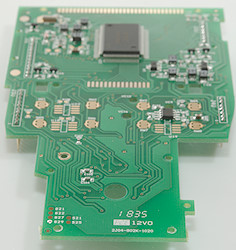
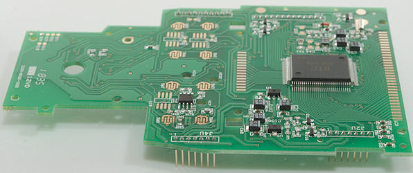
The top circuit board has pads for the rotary switch and a lot of connections to the bottom board.

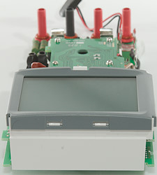
There was two screws holding the display in place.
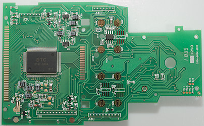
The chip (U23: BTC 0197-0A0A) is definitely a LCD driver, it may also be the main processor in the meter, there is a EEPROM (U17: S24CS02: 256 bytes) between the keys. This board is used in multiple models as can be seen on the marking at the lower right.
Conclusion
This meter has a lot of protection and mounted the right way, it do also have very large fuses. There is one caveat, it is rated for 1000V, but many ranges has a maximum of 600V.
All the common ranges are present and also a lot of extra functions like Peak, Average, Dual-display, AC+DC. This makes it a very universal high end meter with just about any desired function. I would have liked better support for LED testing.
Notes
How do I review a DMM
More DMM reviews
Multimeter design, this explains a lot more about DMM's than my tear-downs