DMM East Tester ET3240
This is a low end bench meter with interface for computer control.
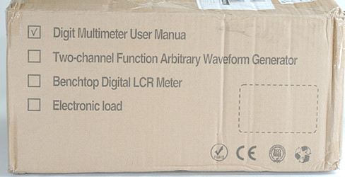
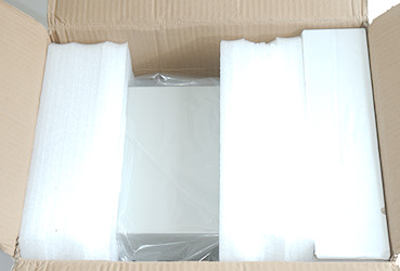
It arrives in a big very solid cardboard box with the DMM well protected inside.
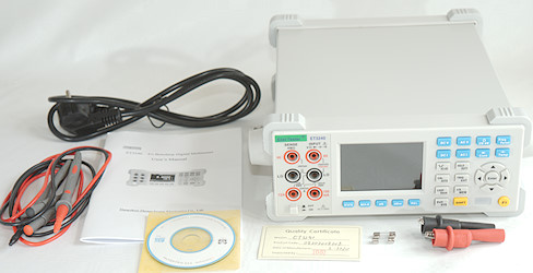
It includes the meter, a manual, a calibration certificate stating that the meter is in calibration, mains cable, a pair of probes with alligator clips and spare fuses.
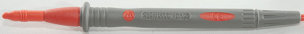
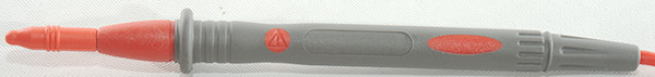
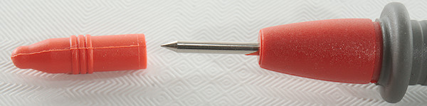
Standard probe, that looks like CATII types.
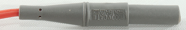
The plug is fully shrouded.
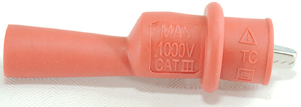
Isolated alligator clips to mount on the probes.
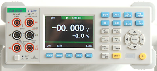
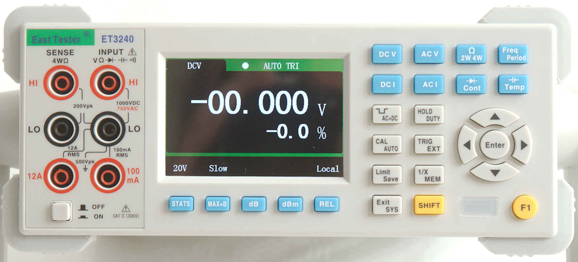
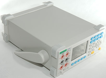
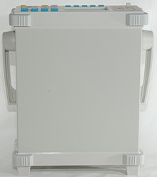
The front has the display, the buttons and the input.
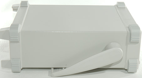
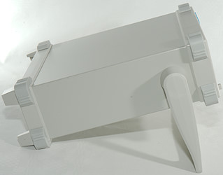
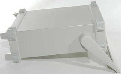
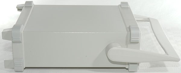
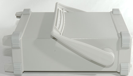
The handle can be placed in many positions, but the locking is rather loose.
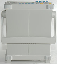
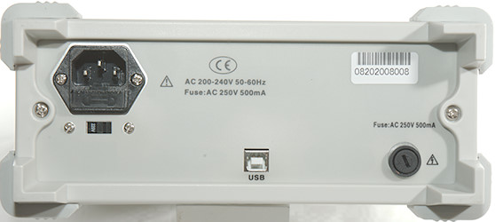
On the bag is mains input with a fuse, a USB connector and the mA fuse.
Display
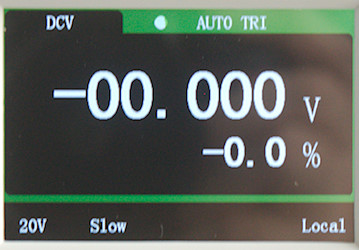
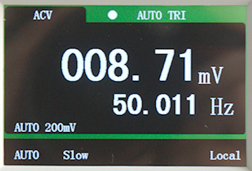
The display uses a color LCD with a main value and a secondary display that is very well used to show secondary values selected with the blue buttons. Default secondary reading is percent of range or frequency for AC measurements.
The bottom of the screen is used to show the current settings, the blue buttons are NOT soft keys.
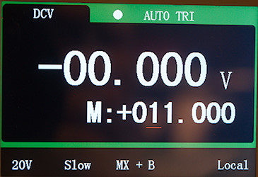
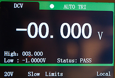
Adjusting some settings for MAX+B and Limits mode.
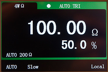
A four terminal ohm reading of a 100ohm 0.01% resistor.
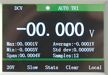
Statistic.
Functions
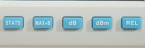
- Stats: Select statistic mode, this works in voltage, current, resistance, capacitance and frequency.
- MAX+B: Show a calculated value (Y) on secondary display. Use enter and arrows to configurate multiply and sum factors.
- dB: Show dB relative to 1V (default) on secondary display.
- dBm: Show dB relative to 600ohm (default) or 0.775V on secondary display.
- REL: Relative mode, current value is used as reference and shown on secondary display. Will also change between 2W/4W mode with RTD sensors.
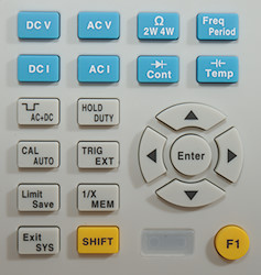
On some buttons the SHIFT function are the top line on other it is the bottom line.
- DC V: DC voltage, always starts in 20V range.
- AC V: AC voltage.
- Ohm: Press once for two wire ohms and twice for four wire ohms readings.
- Freq/Period: Press once for frequency and twice for period.
- DC I: DC current.
- AC I: AC current.
- Cont: Press once for continuity and twice for diode mode.
- Temp: Press once for capacitance and twice for temperature. In temperature the arrows select sensor type and ENTER is used to enter the ambient temperature.
- AC+DC: Press SHIFT and then AC+DC to AC+DC measurement in AC voltage and current.
- Hold/Duty: Press to freeze reading, use SHIFT first to select duty cycle mode.
- Cal/Auto: Press to select auto range, use SHIFT first for calibration (6 digit password required).
- Trig/Ext: Press to enter single measurement mode, each press will do a new measurement. Ext is not used on this meter.
- Limit/Save: Press to save subsequent measurement (Works fine with TRIG). Press SHIFT first to select limits and alarm mode (Use ENTER and arrows).
- 1/X/MEM: Press to read the saved values, use SHIFT first to show 1/value on secondary display.
- Exit/Sys: Press to see/set system stuff, use SHIFT first to leave some modes.
- SHIFT: Must be pressed before some keys to activate the function.
- F1: Keyboard lock.
 : Arrows and ENTER are used to adjust and select values/ranges.
Input
The inputs are only CAT II 300V rated, i.e. the meter is not designed for industrial and service on electric installations.
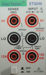
- HI: The voltage, frequency, capacitance, diode, etc. positive input.
- LO: The voltage, frequency, capacitance, diode, etc. negative input.
- HIsense: Four terminal ohm.
- LOsense: Four terminal ohm.
- 100mA: Current low input, meter is rated for 240mA on this terminal.
- 10A: Current high input
Measurements
- Volt and frequency
- At 100mVrms frequency input range is from 1Hz to 20MHz (The dual display voltage/frequency is limited to 120kHz).
- Frequency counter can handle a DC offset of at least 9.8V when measuring 0.1Vrms (The input impedance will be fairly low).
- Duty cycle works from 5% to 95% at 10kHz with 1Vpp, precision is within 3.0 (Higher input voltage do not improve readings).
- 1 VAC is 5% down at 120kHz, rms will not work at this frequency (It looks like the meter applies a correction depending on the measured frequency).
- Period is 1/frequency, it do not show high/low period time.
- Min/max captures in about 160ms on fast speed, but requires a couple of samples.
- Min/max is based on normal measurements, there is no special mode/circuit to make faster captures, this is standard for bench meters.
- Meter can show dB with either 1V (Adjustable) or 600ohm (Adjustable from 1 to 9999ohm) reference level.
- Input impedance is 10Mohm on the high DC ranges.
- Input impedance is 1Mohm capacitive coupled on AC ranges, but DC couple when using AC+DC.
- mVDC & 2VDC range is high impedance.
- Frequency input is a few kOhm above 3V
- Current
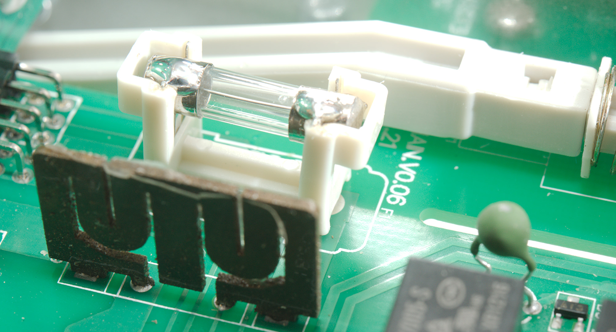
- Low current ranges is protected with a 0.5A/250V 5x20mm glass fuse accessible from outside.
- High current ranges is protected with a soldered 5x20mm glass fuse.
- Most current ranges has their own shunt instead of a x10 amplifier, this means better precision, but also higher voltage drop on some ranges.
- mA current terminal will disconnect shortly when changing range.
- There is no warning about using the wrong current input terminal, but the reading will be wrong.
- Ohm, Continuity, diode and capacitance
- Ohm needs about 2.4s to measure 100ohm in default slow and about 1.8s on fast.
- Ohm is up to 3.2V open (1V in 200Mohm range) and 0.67mA shorted
- Continuity speed is moderate (About 100ms).
- Continuity beeps when resistance is below 30ohm, this is adjustable from 0 to 2000ohm
- Continuity is 3.3V open and 0.16mA shorted
- Diode range uses 3.3V, max. display is 1.64V at 0.35mA, max. current is 0.67mA shorted
- 10uF takes about 3 seconds to measure.
- 1000uF takes about 16 seconds to measure.
- Miscellaneous
- I did not find a ambient temperature compensation, the ambient temperature must be entered manually for thermocouplers.
- PT & Cu sensors can both be used in 2 wire and 4 wire mode, it is changed by the REL button.
- The calibration procedure is documented, but it requires a 6 digit password and that is not documented.
- Power consumption when on is 4.4 watt
- Viewing angle is good.
- Display update speed depends on settings (2, 5, 7 / second)
- Weight is 2200g including bumpers.
- Size is 300 x 270 x 104mm including bumpers and handle.
- Probes
- Probe resistance 32mOhm for one.
- Probe wire is very soft and 104cm long.
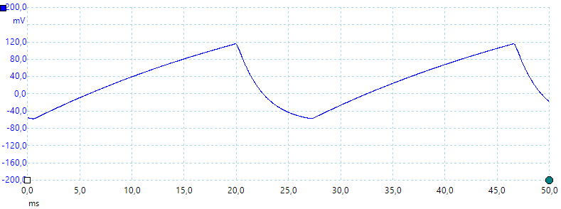
A look at the capacitance measurement waveform.
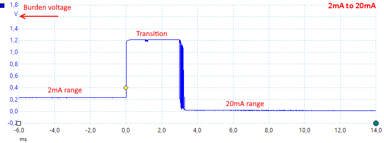
Current auto range, there is a few ms where the burden voltage is due to the protection diodes, not the shunt resistors. It looks like there is some contact bounce on the relay.
From 20mA to 200mA the voltage drop is about 1.4V, but the time is shorter.
The meter has a slight issue in the high mA range, the input terminal is labeled 100mA, but the range is 240mA
High AC voltage can block DC readings.
AC voltage is 1Mohm input impedance.
Software
The meter includes a CD with software and manual, but that was a rather big disappointment.:
- The manuals on the CD cannot be opened by a PDF reader.
- The program is in both a 32 & 64 bit version, when installing it the only thing I got was a STM serial port driver.
- The meter do not include any documentation for the SCPI protocol (I got it directly from Banggood).
- The protocol is not correct SCPI.
- There are some bugs in the protocol, like 200A range when selecting 2A or 10A range and missing temperature.
- Temperature is not supported in the SCPI protocol.
There is one good detail with the implementation: it answers very fast, sampling at the fastest conversion speed is no problem.
I implemented the meter in TestController, here is some examples:
I support most modes in the meter
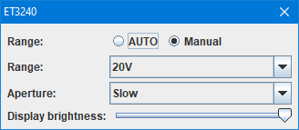
And some configuration, this is present for all modes with ranges.
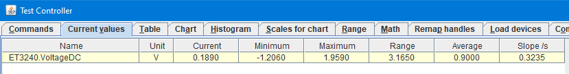
Getting the current reading from the meter and showing some statistic.

Large digit readout on the desktop.
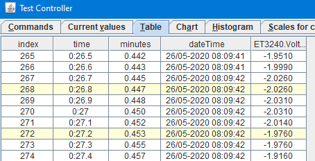
Collecting the data in a table.
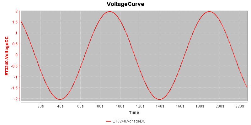
Making a curve of the data.
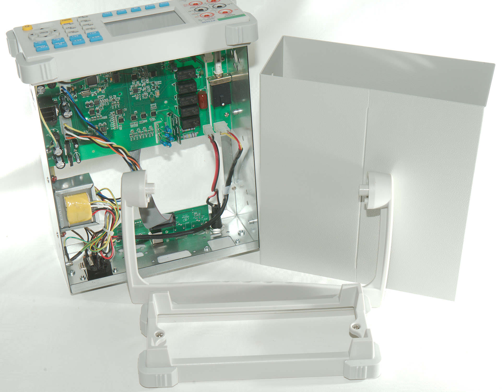
Tear down
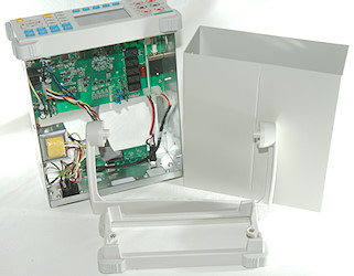
To open it I had to remove two screws and pull the handle out.
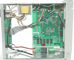
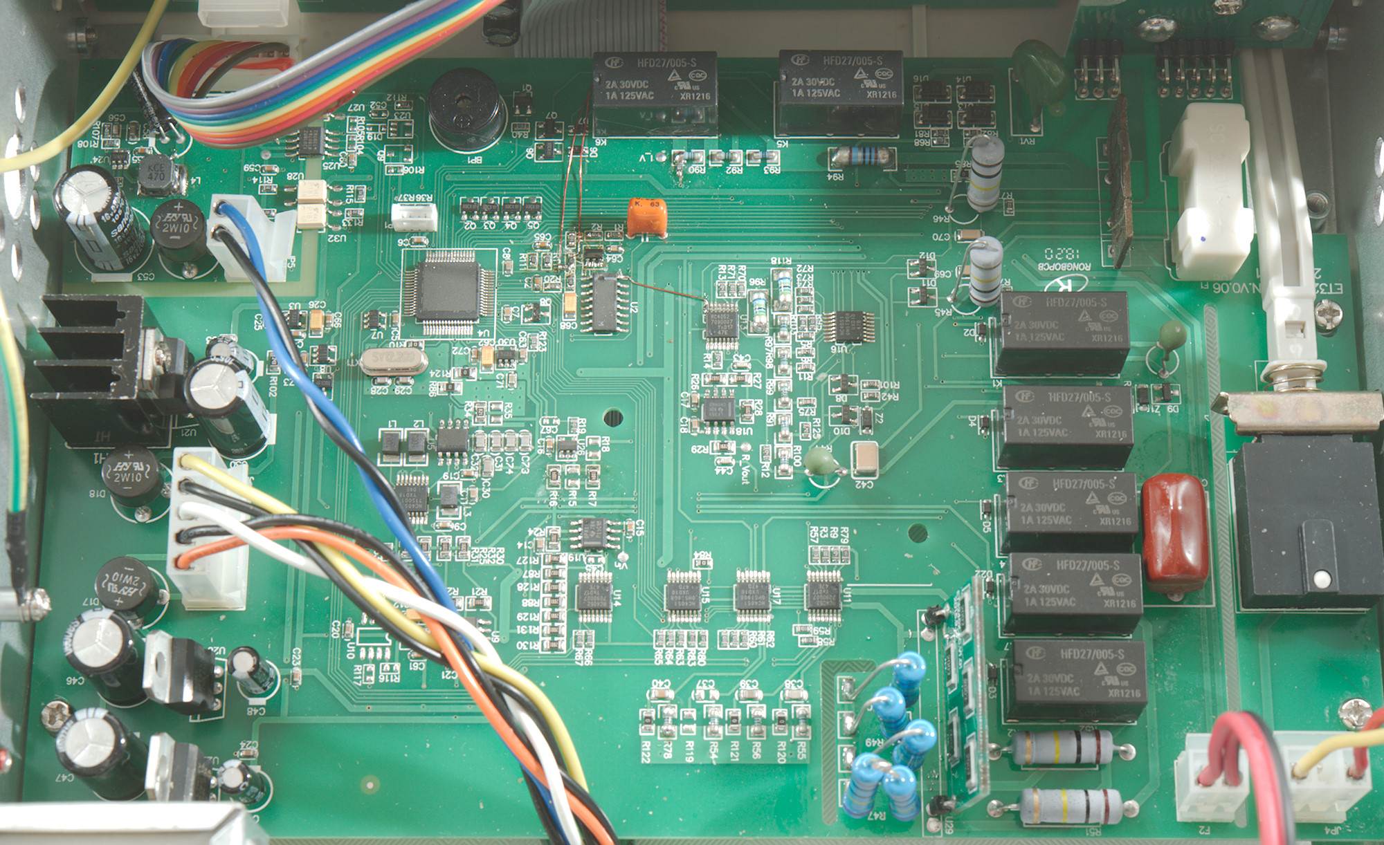
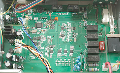
Most of the meter is on a single circuit board. There is a IO board at the back. The main input goes to the circuit board where the switch is mounted and then back to the transformer. There is a isolation slot between the mains part and the rest of the circuit (nice).
The mA fuse is connected to the circuit board with wires and a connector.
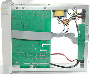
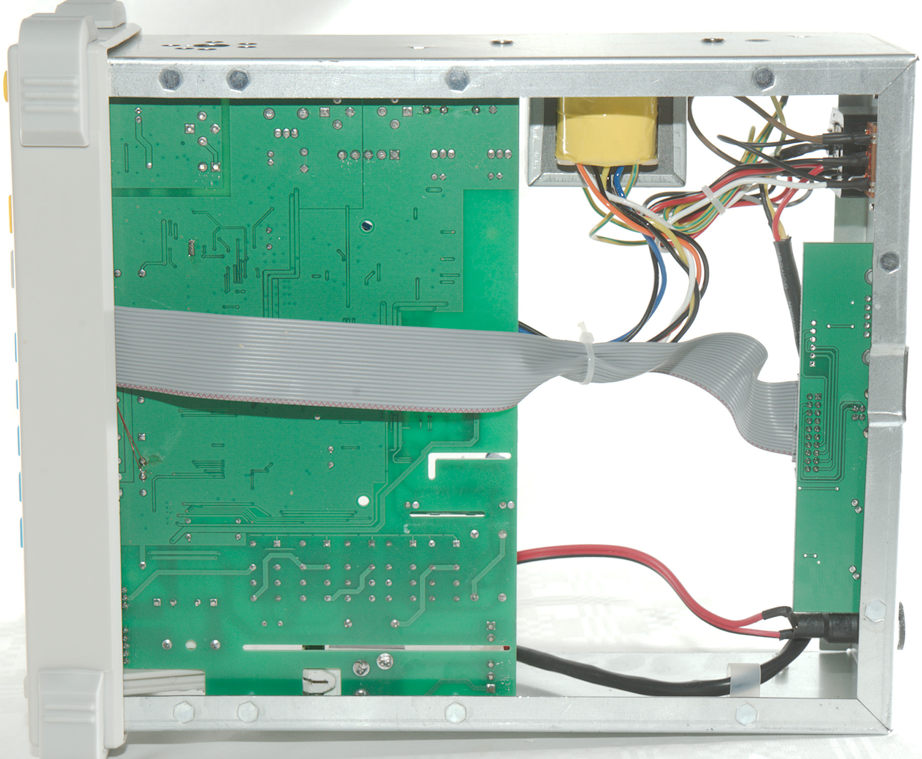
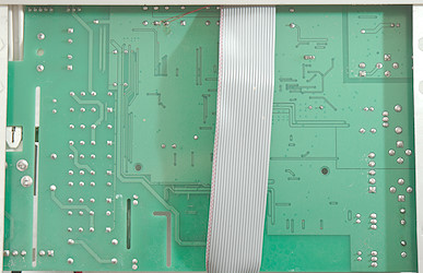
There is no parts on this side of the circuit board.
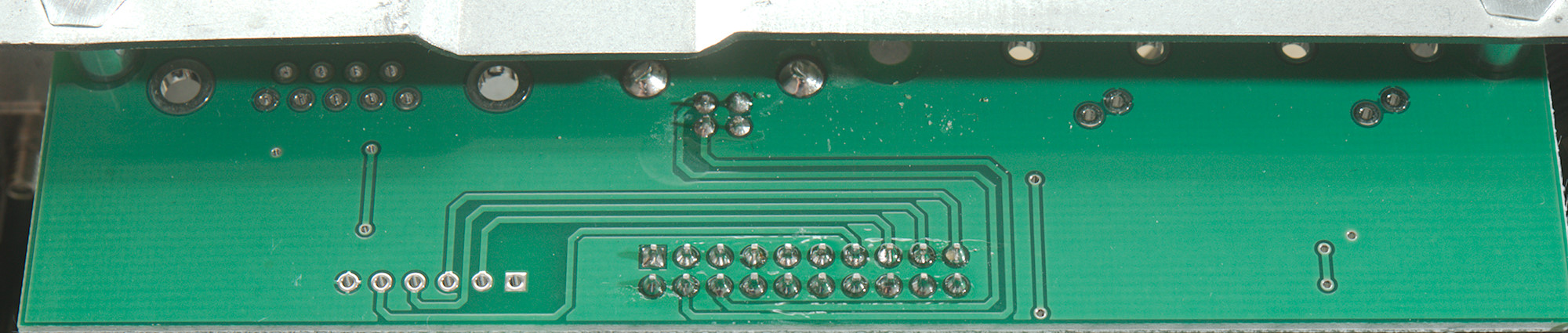
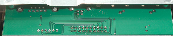
A closeup of the backside of the circuit board. two budge wires can be seen.
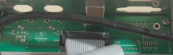
The IO port only have the USB connector mounted. These is also space for a RS232 output with a driver chip and for trigger and square wave connectors.
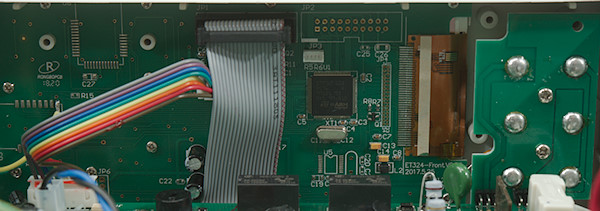
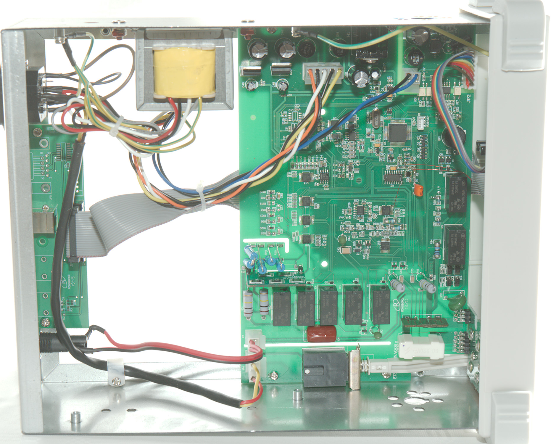
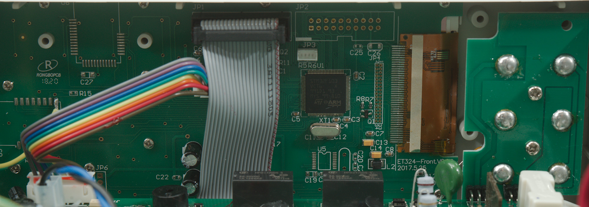
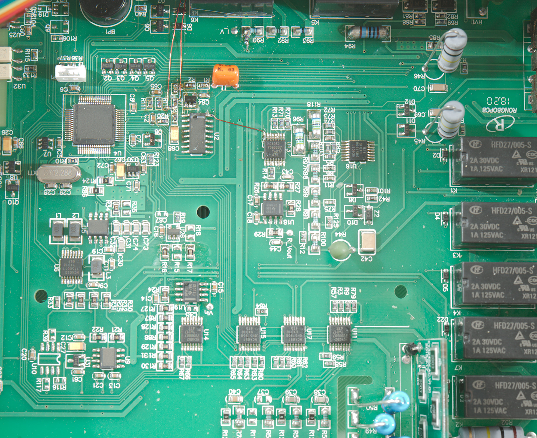
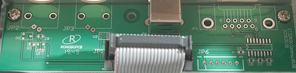
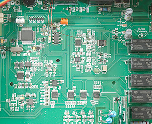
The front side circuit board. The flat cable is for USB connector, it is handled here. It also looks like the trigger and square wave may be controlled from this processor.

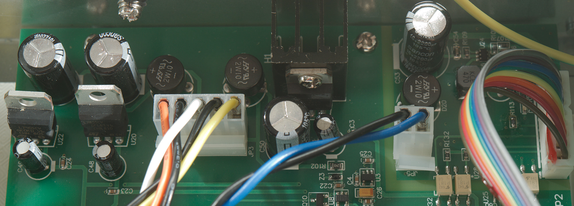
The power supply part of the circuit board. It looks like +/- 5V (U20 & U22: 7805 & 7809) and a more powerful 5V (U21: 7805) with heatsink.
Next is a isolated switching supply for the front panel, it also has opto isolated connections to the main board
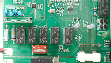
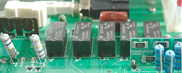
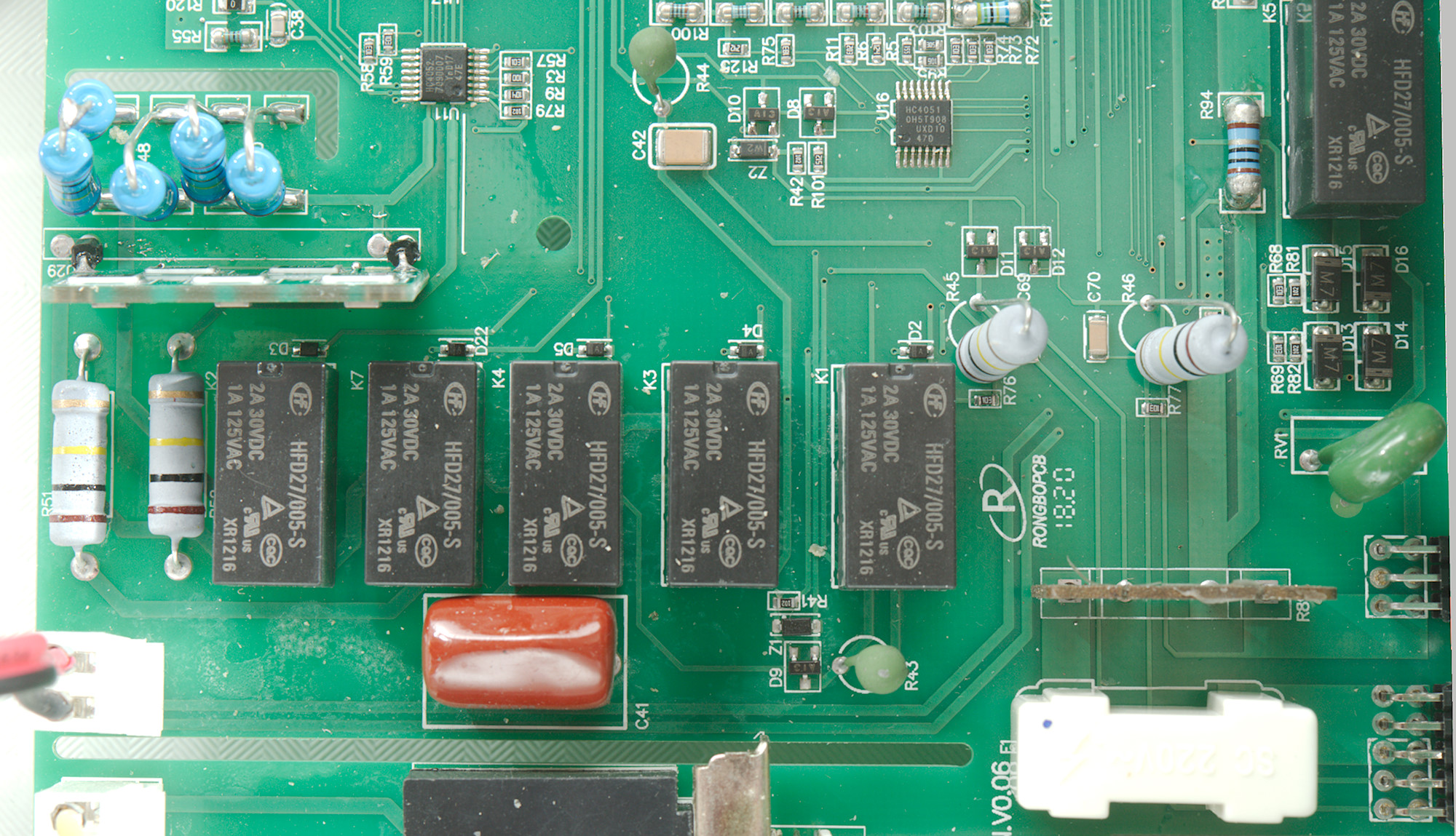
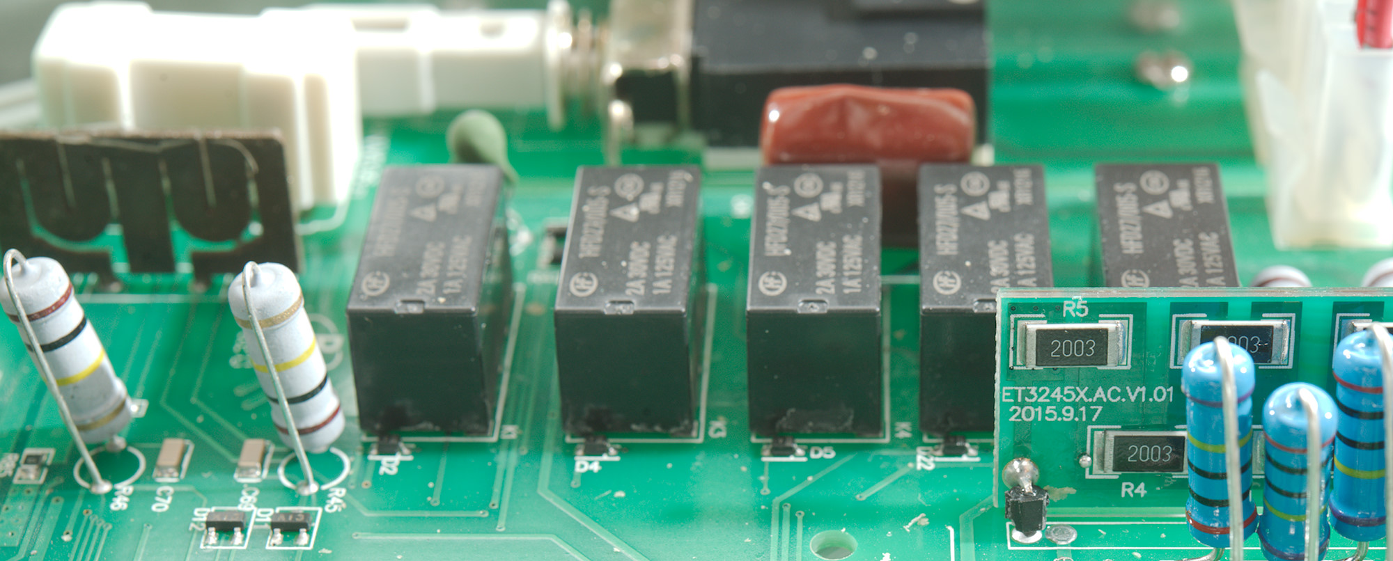
This part is the electronic range switch, a large part of it is done with relays. There is a big red input capacitor for the AC ranges.
There is four diodes (D13..D16) that handles overload on mA ranges and limits the voltage drop when changing current range.
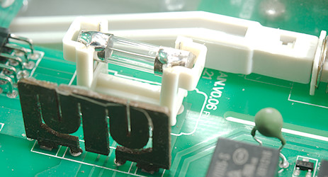
The 12A range has a fuse, but it is soldered into a isolated holder.
Conclusion
The meter measures nicely, but the user interface is not completely logical, sometimes a specific function can be a bit hard to locate.
The computer interface is lagging documentation and software, I got the documentation from Banggood and the last bit can be solved nicely with my software.
Generally it works fine as a low end bench meter and I prefer it over the bench meters that are basically a handheld meter in a large enclose with a power supply.
Notes
Download TestController from here
How do I review a DMM
More DMM reviews