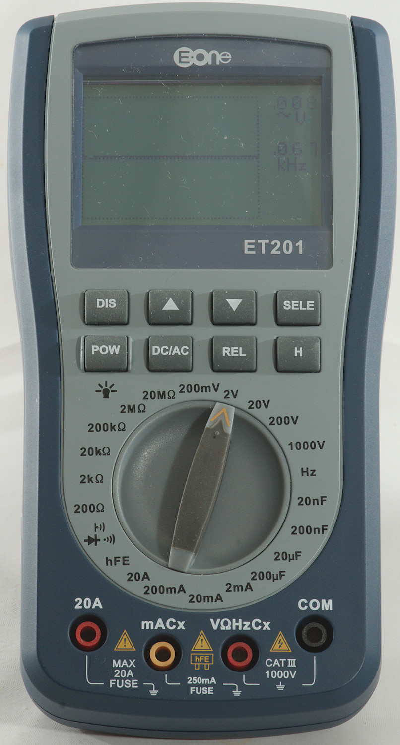
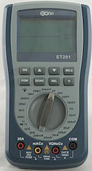
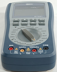
DMM Eone ET201
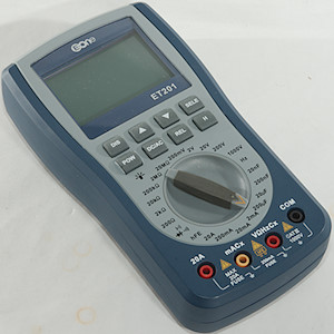
This is a DMM that can also show waveforms.
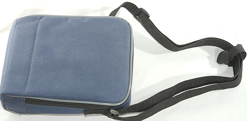
I got the meter in a bag with a shoulder strap.
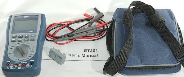
It included the DMM, a pair of probes, a transistor tested adapter and a manual.
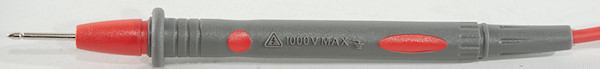
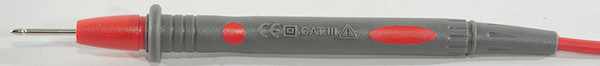
The probes are without tip covers, i.e. they are only CAT II rated.
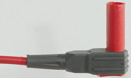
The plug is fully shrouded, but is slightly smaller than standard probe plug size.
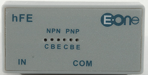
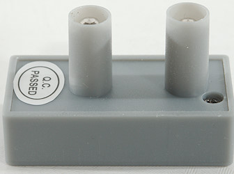
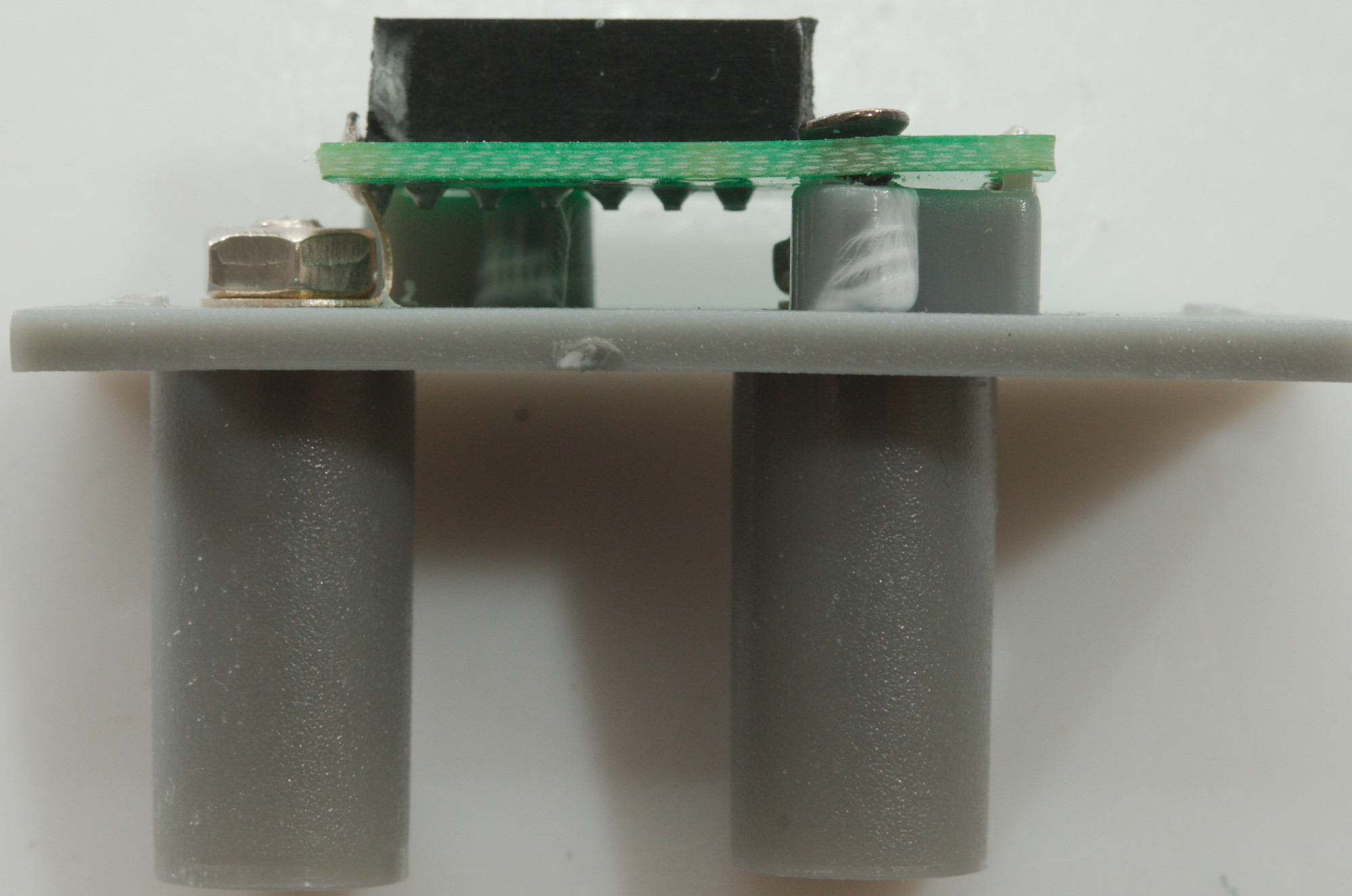
The adapter for testing transistors is a very simple one, that can only be used for small leaded transistors.
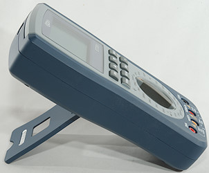
The tilting bale is rather soft, but can hold the meter while pressing buttons and turning the range switch.
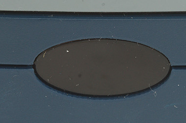
There is a IR filter on the front, it is a simple remote control tester.
Display
There is no special power on screen.
The display is a graphic display, this gives some flexibility with showing symbols and units.
The display has low contrast and background light do not help.
The display have a log of saved values.
And it can show waveforms.
Functions
Buttons:
- DIS: Show waveform or return to main screen.

 : Use for page up/down when showing recorded data and for adjusting time in waveform display.
- SELE: Do an auto scaling in waveform display. Works as clear key for recorded data.
- POW: Power on/off and backlight on.
- DC/AC: Change between DC and AC in volt and current modes.
- REL: Remember current value and show values relative to this, this function is indicated with a triangle on the display.
- H: Freeze the display value. Hold down this key to enter the log, it will always start empty (Values are never saved when outside the log display).
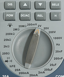
Rotary switch:
- 5 x V: The voltage ranges, use DC/AC to select between DC and AC.
- Hz: Frequency range, this is auto ranging.
- 2 x nF & 2 x uF: capacitance ranges.
- 3 x mA & A: Current ranges, use DC/AC to select between DC and AC.
 : Continuity, diode and IR test, all are on the same range, no selection is supported.
- 6 x ohm: Ohm ranges.
Input
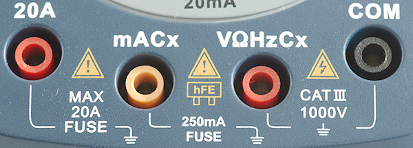
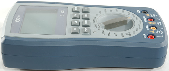
If you have multiple meters, be aware that this meter has placed the COM connection different than other meters.
- 10A: High current.
- mACx: The lower current ranges, capacitor ground and Hfe adapter.
- xxx: All other ranges.
- CON: The common terminal for most ranges, capacitor is excluded from this.
Log function
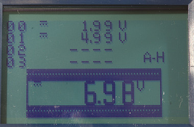
The log display looks nice, but it do not work very well. It is only supported in voltage and current modes.
The lines marked 00, 01, 02, etc. are the log entris, there is space for 100 entries. The value below is the current input voltage or current.
Hold down H to change into this mode.
To arm trigger input voltage must be about zero (0.01V and below works).
The a stable input value will be capture and show in the log.
To capture a new value, the trigger must be armed again.
To stop capturing hold down the H key (The A-H test disappears) .
To exit hold down DIS when capture is stopped.
Turning the range switch to a mode that do not support logging will also exist it.
Arrows can be used to move up and down in the list of values.
Waveform function
I will not call this function a oscilloscope function, but a waveform display function, it do not support enough functionality for a oscilloscope.
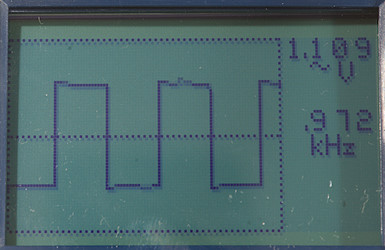
A press on the DIS key will show the waveform screen, usually a press on SELE is needed to do a auto ranging and get a nice waveform.
Pressing or will change the timing, i.e. show more or less of the curve.
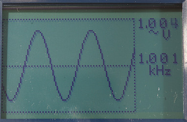
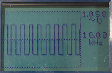
The voltage shows 1.1VAC, this is not correct, the voltage is 1Vrms AC, but the meter is not a RMS meter and it do not show the scale of the chart.
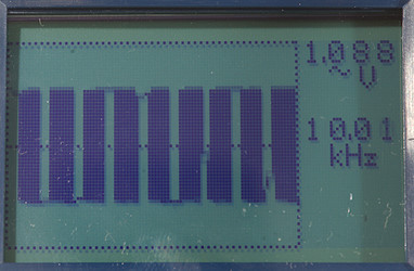
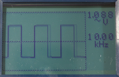
Here I switched the generator to 10kHz, the frequency counter got it, but the display did not.
Some timing adjustment and I can view the 10kHz waveform.
When zooming more in on the waveform the display/sampling is slightly unstable. The display shows two curves, but my generator delivers a very stable waveform, this means it is the meter.
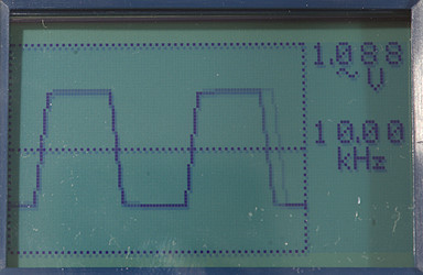
Zooming even more and I can see rise and fall times, not for the curve, but for the meter.
Meter will switch to AC mode when selecting waveform display, smaller DC offsets will be removed, but larger DC offset will affect the curve.
Here I have a 7V DC offset and the curve is clipped. In 2V range 5V offset is fine, more and it will clip
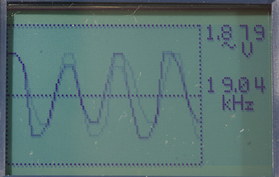
At 19kHz the sinus curve do no look very good, I had to get down to 2.5kHz for a stable and good looking curve.
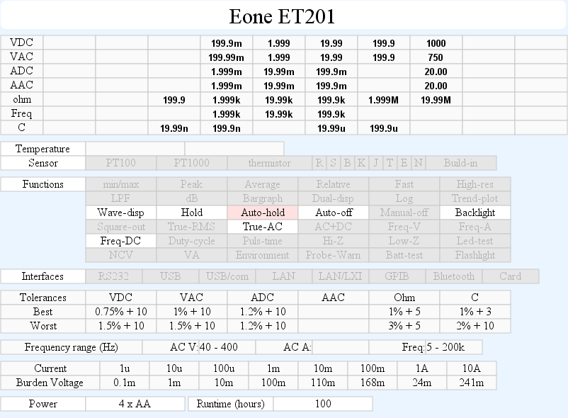
Measurements
- Volt and frequency
- At 1Vrms frequency input range is from 5Hz to 200kHz
- Frequency counter works with +/-8.5V offset with 1Vrms input
- 1 VAC is 5% down at 25kHz
- Input impedance is 10-11Mohm on DC and AC, including mV
- Frequency input varies in impedance at low voltage, but at 20V it down to 2kOhm
- There is audible alarm on overload on any voltage range.
- There is a short beep and high voltage indicator turns on when voltage goes above 24VAC or 36VDC
- Maximum voltage is 1000VDC and 750VAC, for frequency input it is 380V
- Current
- mA protected by a 0.4A/250V 5x20mm fuse
- Cx/mA is also protected by a 0.4A/250V 5x20mm fuse (There is two fuses on this terminal)
- A is protected by a 20A/250V 10.3x38mm fuse.
- There is audible alarm on overload on current ranges
- Ohm, Continuity, diode and capacitance
- Ohm needs about 1.5s to measure 100ohm, it is fast due to manual ranging.
- Ohm is 0.62V open and 0.5mA down to 0.06mA shorted
- Continuity is fast (About 20ms).
- Continuity beeps when resistance is below 100ohm .
- Diode and continuity range uses 3V, max. display is 1.999V at 0.3mA, max. current is 1mA shorted
- Diode and continuity range will sound the beeper if 38kHz IR is detected on the front sensor.
- 10uF takes about 0.8 seconds to measure, manual ranging helps with the speed.
- 100uF takes about 0.8 seconds to measure.
- There is audible alarm on overload on capacitance range
- Note capacitance is measured between mA and V terminal.
- There is no overload rating for capacitance and resistance.
- Miscellaneous
- Current consumption of meter is 24mA (20mA extra with backlight)
- Display starts to fade at 3.2V and meter turns off at 2.9V, battery symbol show at 4.3V.
- Meter has drifted 2 count at 4.4V and is 7% too high at 4.2V, at 3V it is 70% too high.
- Backlight fades slowly while battery voltage drops.
- The meter usual need many display update to reach the final value.
- Viewing angle is good, but contrast it on the low side.
- Display updates around 2 times/sec
- Backlight will automatic turn off in about 30 seconds.
- Backlight is fairly weak, but gives a smooth illumination.
- Will automatic turn power off in about 11 minutes.
- Standard probes cannot be fully seated (Maybe 1mm)
- Weight is 461g without accessories, but with batteries.
- Size is 187 x 100 x 44mm.
- Probes
- Probe resistance 60mOhm for one.
- Probe wire is soft and 92cm long.
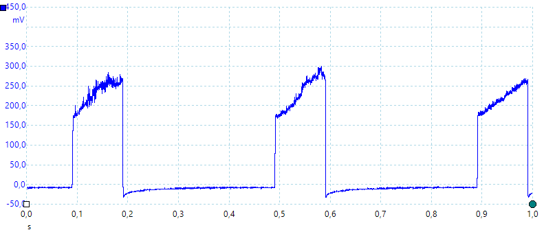
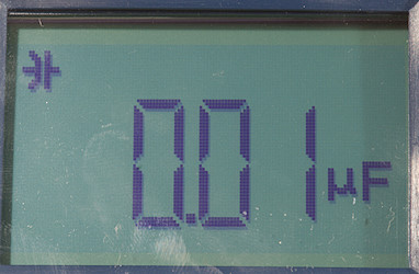
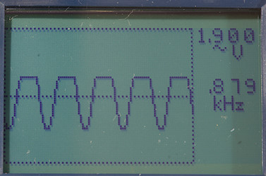
A look at the capacitance measurement waveform for a 1uF capacitor.
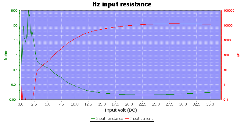
Frequency input impedance.
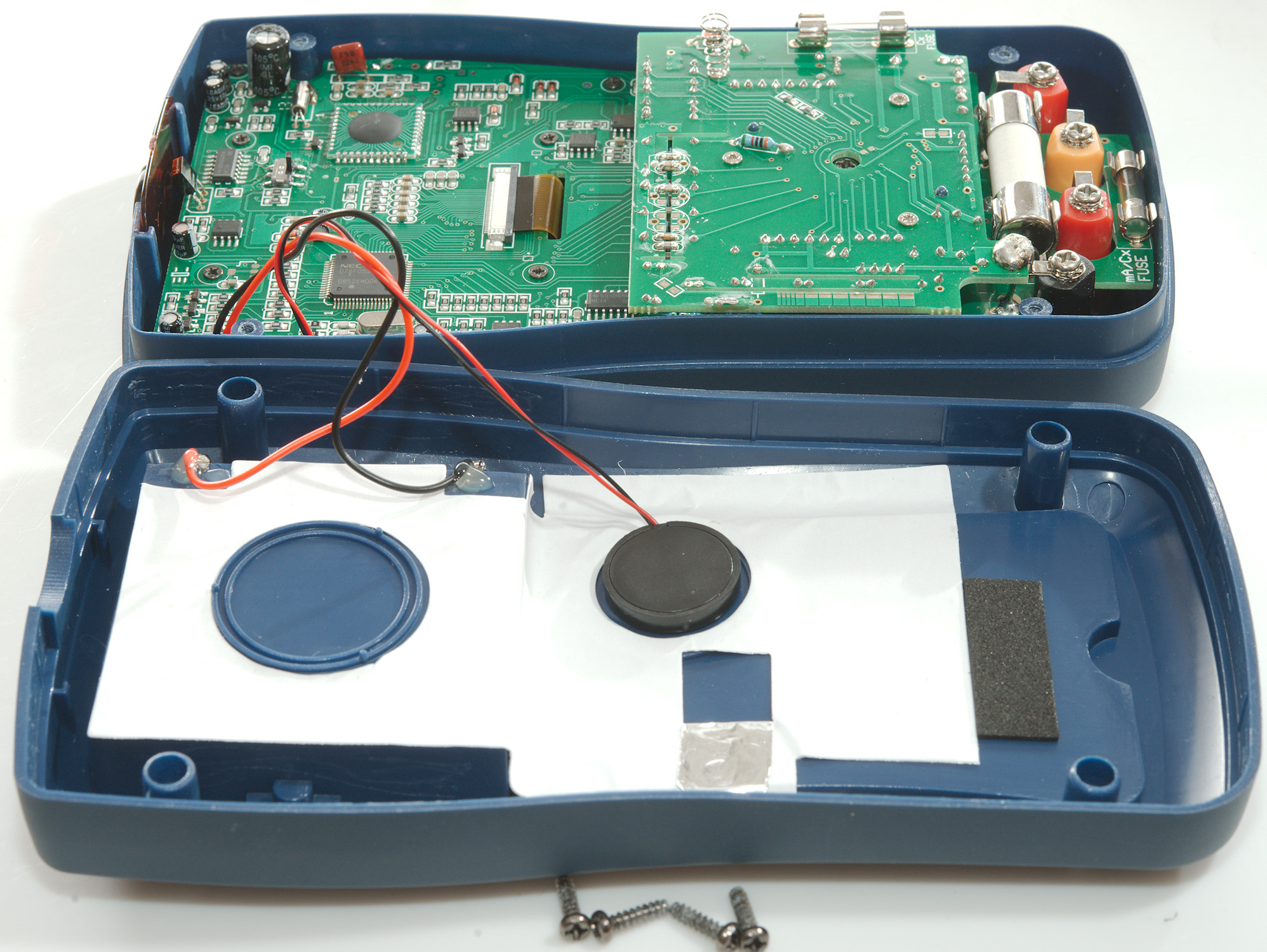
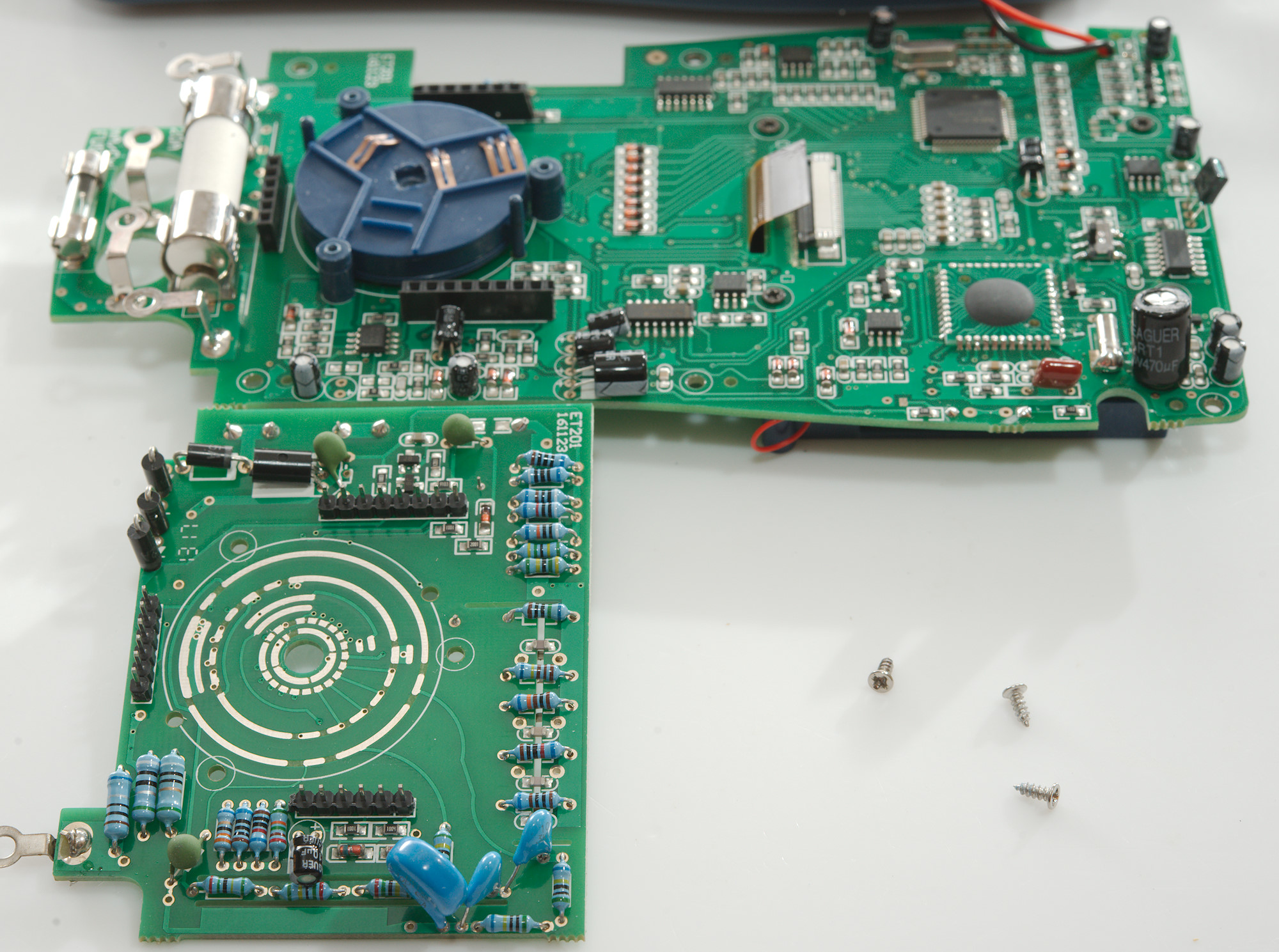
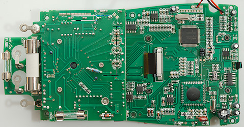
Tear down
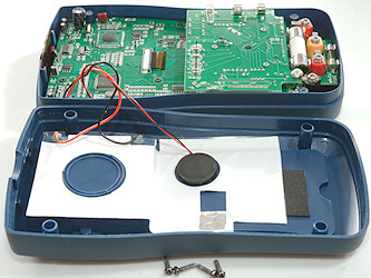
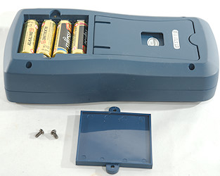
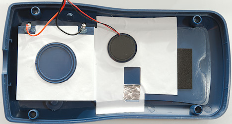
I had to remove four screws to open the meter. Both buzzer and batteries are connected with soldered wires.
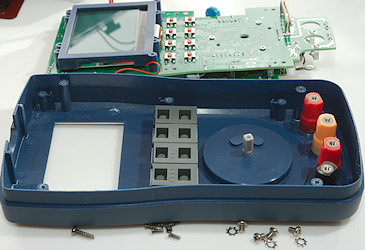
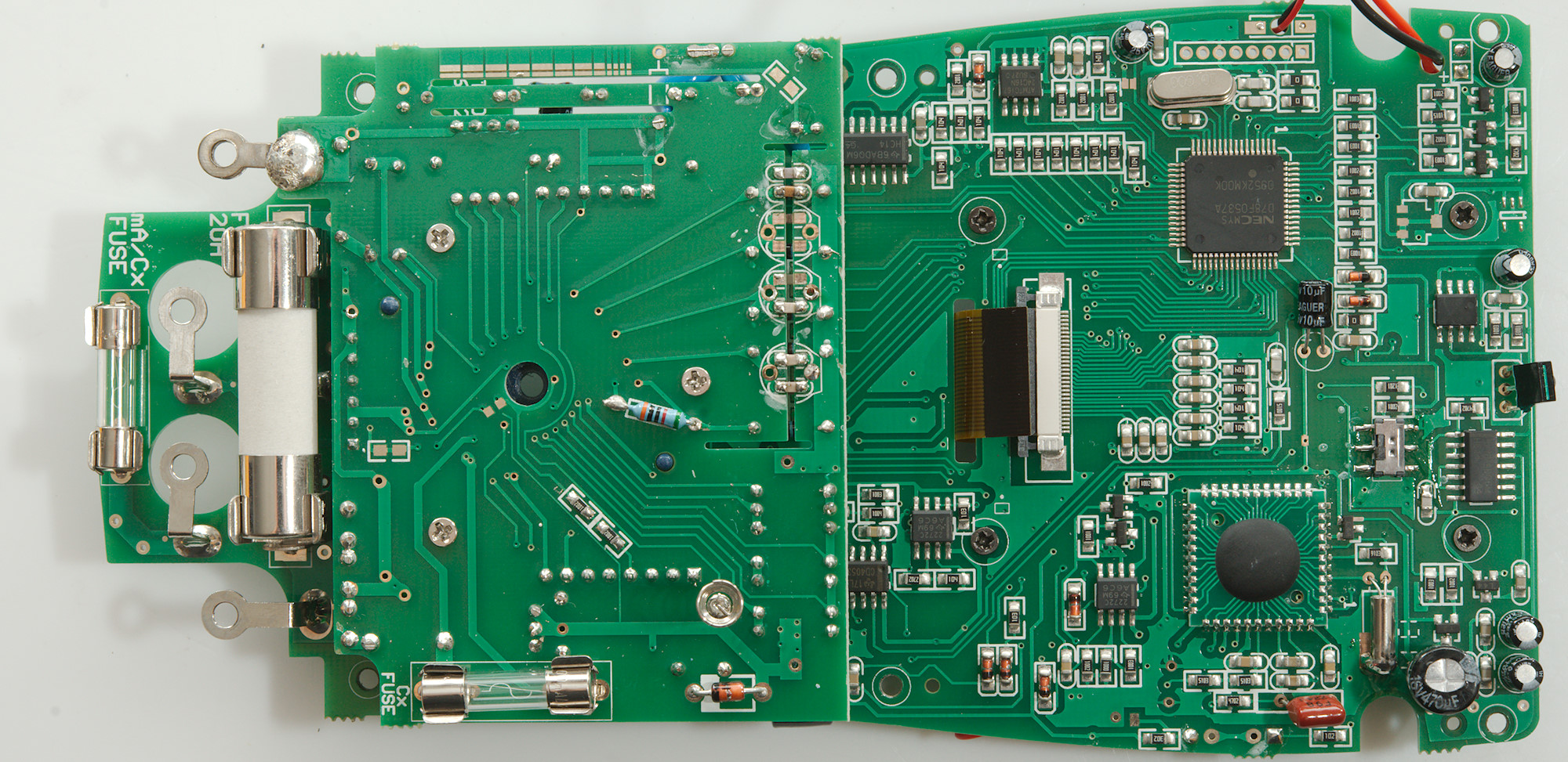
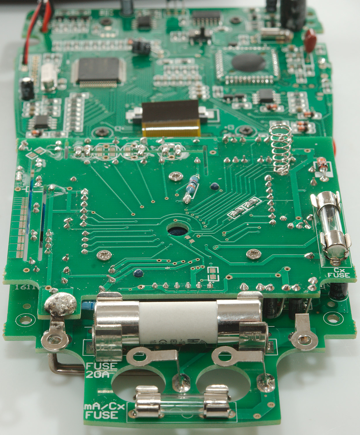
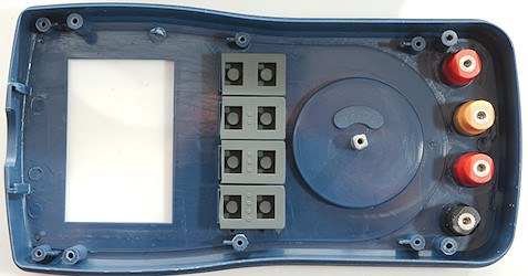
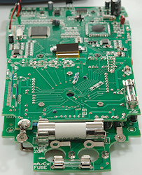
Getting the circuit boards out was 6 screws for the board, one for the range switch and four for the terminals.

It is a two layer construction when range switch on both layers.
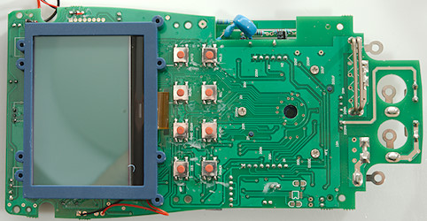
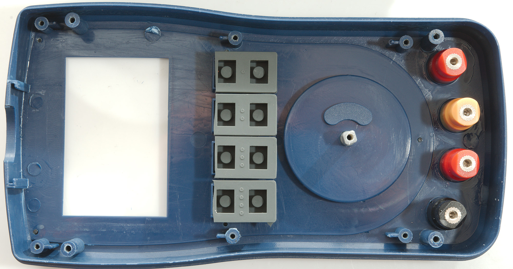
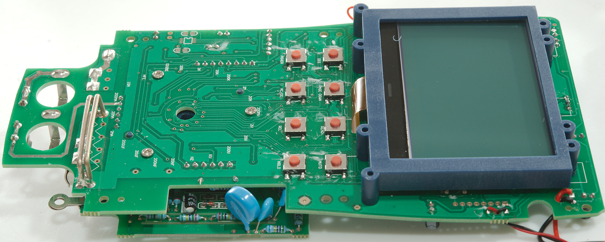
The top side has the switches and the display, there is nothing below the display.
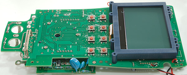
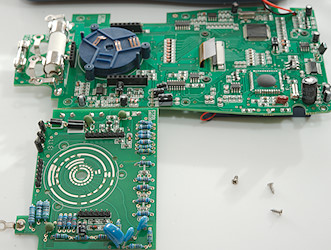
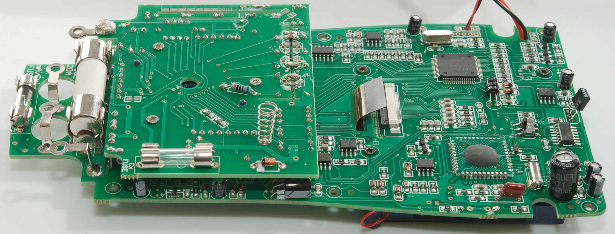
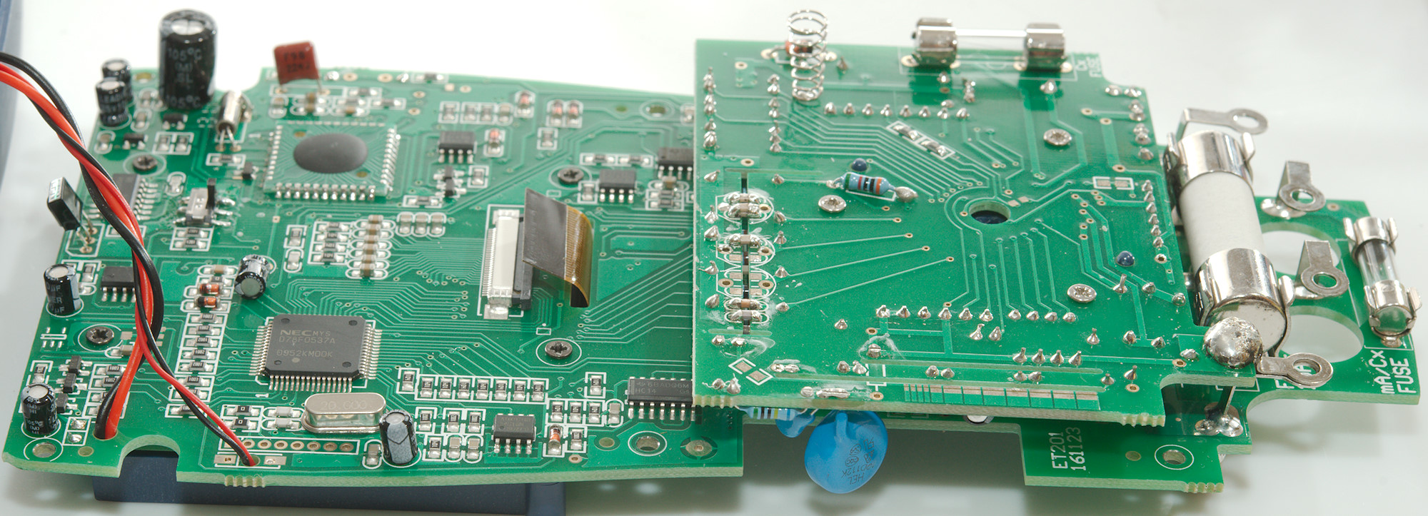
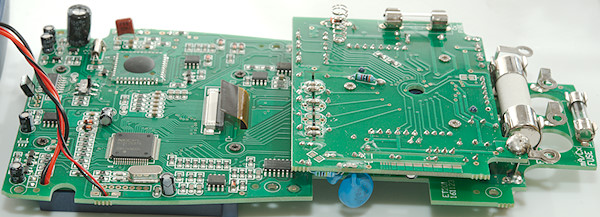
I had to remove 3 screws and unsolder the minus connections to split the two boards.
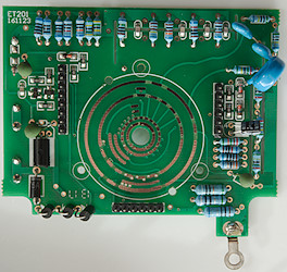
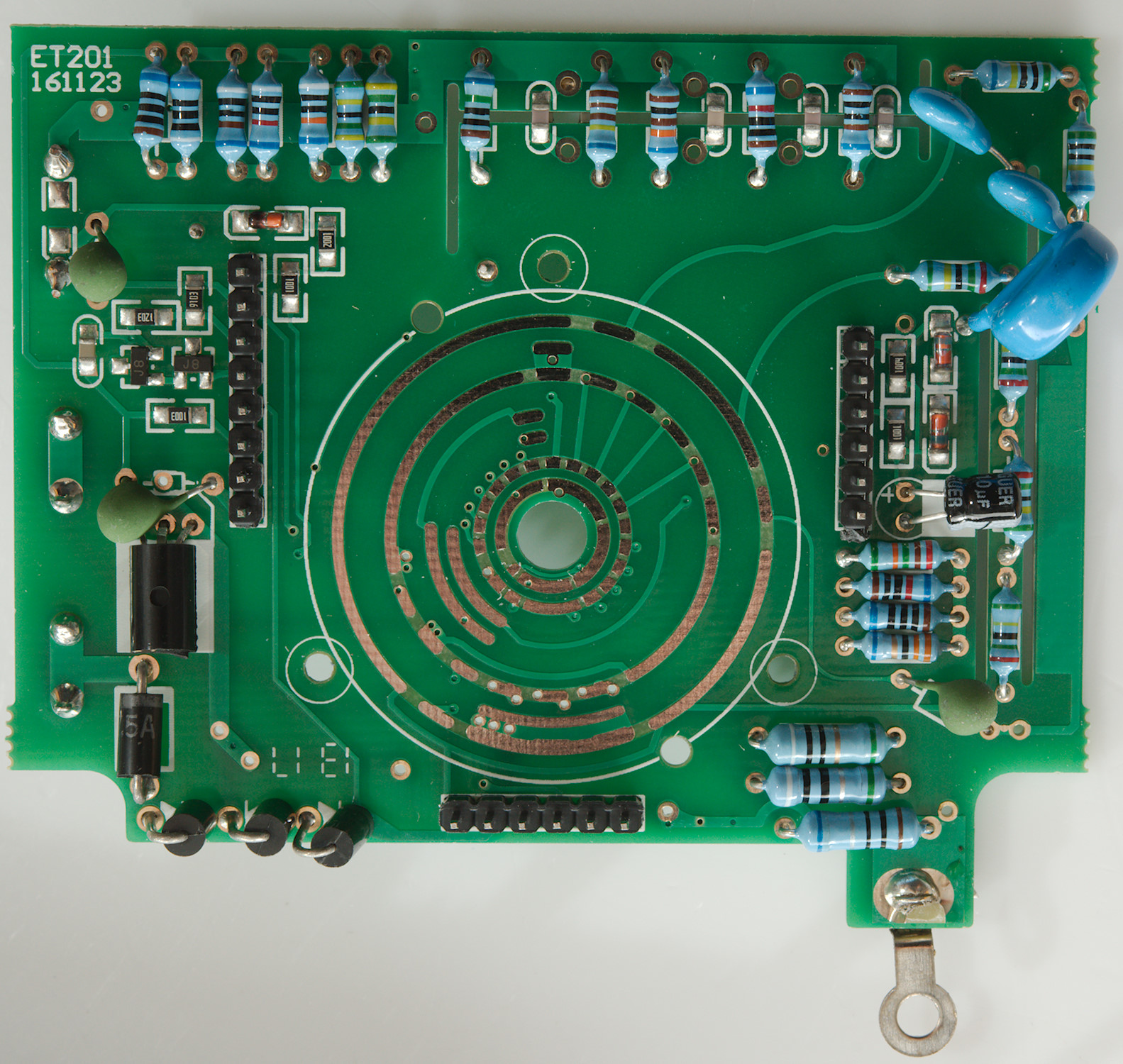
This board looks to be the analog part of the range switch. The 3 resistors near the input connection is the current shunts (1ohm, 9ohm, 90ohm) there is also a diode bridge to protect them from overload. Near the blue MOV is two input resistor (2x5Mohm) with capacitors across for better high frequency handling. There is also a four input resistor (4x2.5Mohm) with slots on both sides. The two smd transistors is a protection transistor pair.
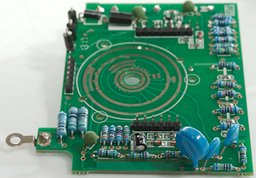
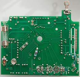
On this side is the fuse for the capacitor range. The capacitors across the slot is probably frequency linearisation.
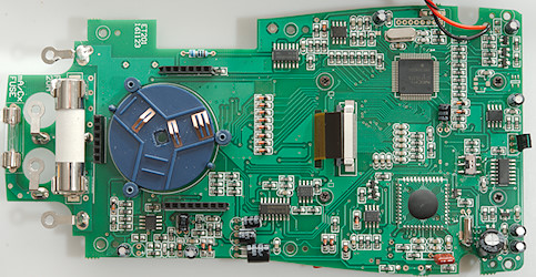
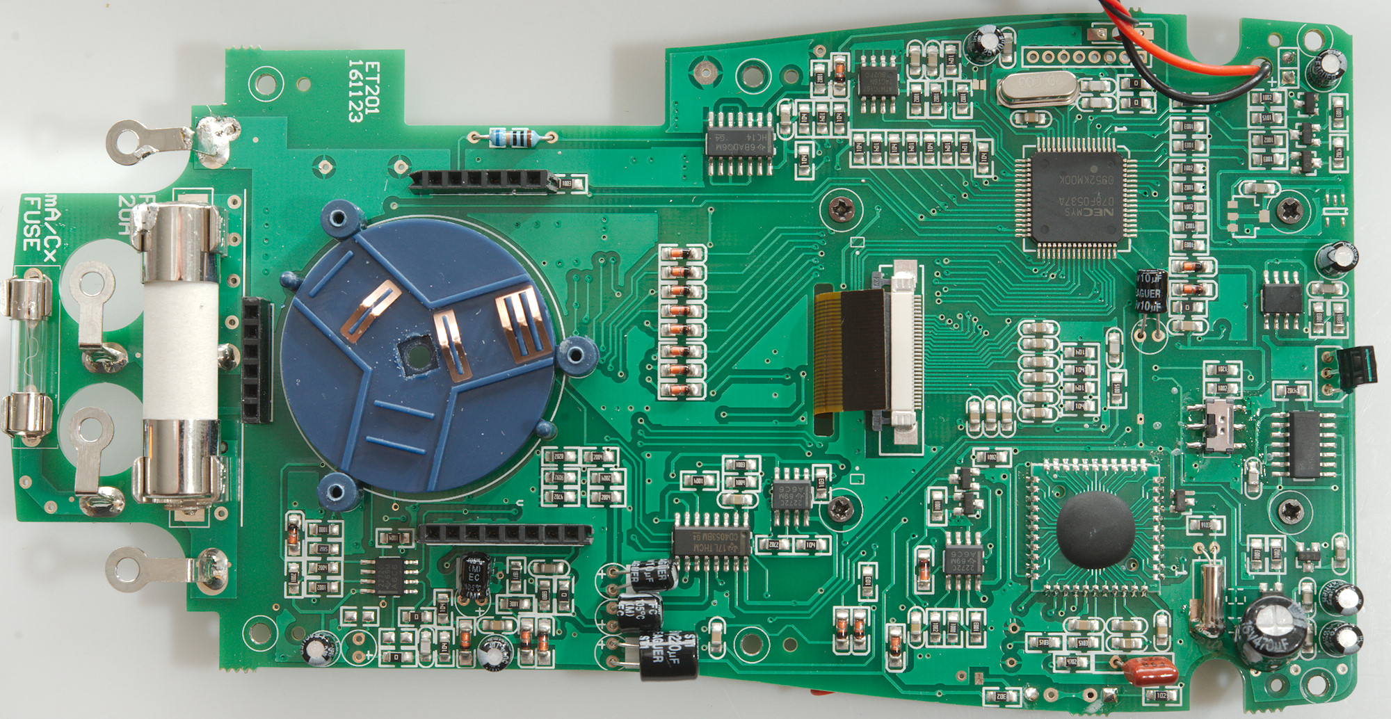
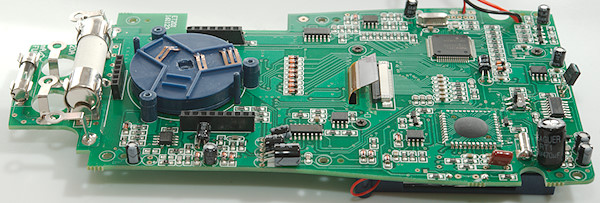
This is the digital board, but it do also have some analog stuff. It looks like most of the 8 pin ic's are OpAmps ((TLC2722), but one is a EEPROM (24C16N) there is a mux (CD4053), two hex schmitt triggers (HC14). There is a microcontroller (D78F0537) to control the meter and a unnamed chip to do all the multimeter and waveform display stuff.
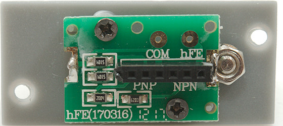
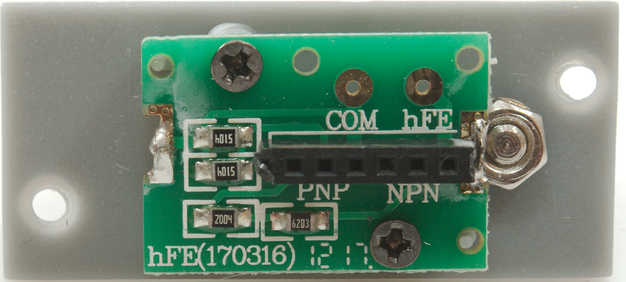
The transistor tester adapter was put together with screws, here is a look inside it, it is a few resistors.
Conclusion
As usual the CAT rating is wrong, a 250VAC glass fuse is not acceptable on a 1000V meter, but will work fine for hobby work.
The meter is a average low-end manual range meter with few functions.
The idea with a waveform display sounds nice and can also be useful to see whats going on, but there are serious limitations on the function. If the frequency is low enough and not too much DC offset it can show the curve, but there is no scales on the curve. Only advantage compare to a scope is that this waveform display can be used on mains voltage.
I am not very impressed with the user interface when saving values.
Notes
This meter exist with other names on it.
How do I review a DMM
More DMM reviews