DMM Hioki DT4282
Hioki is a Japanese test equipment manufacturer, this multimeter is one of their top models.
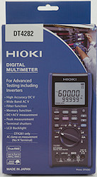
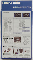
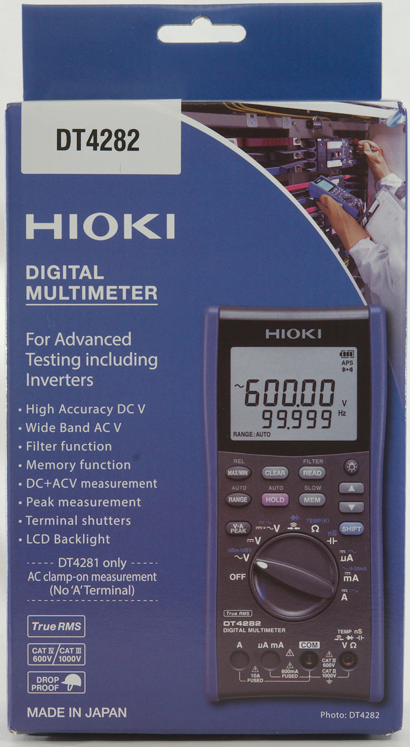
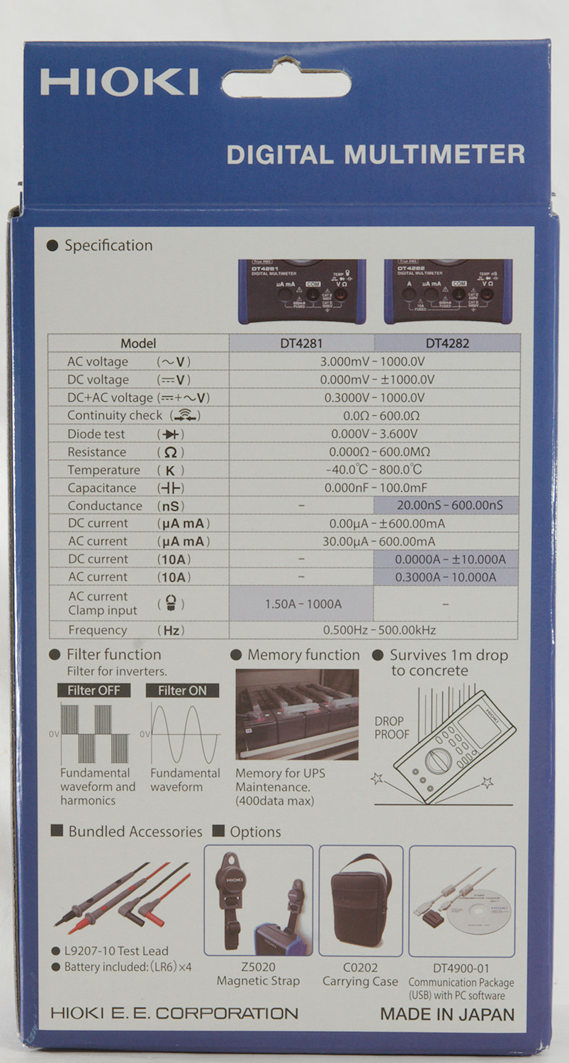
I got it in a cardboard box designed for the two top models, they can be compared on the back of the box. It also list what is in the box and some accessories.
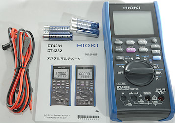
The box contained the meter, batteries, test probes and a manual in Japanese (A English manual can be downloaded). No thermocoupler or pouch.
The manual is very thorough with functions and specifications.
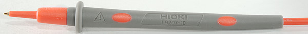
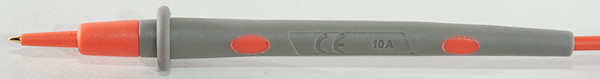
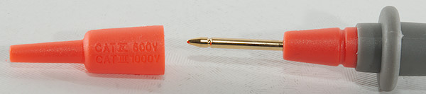
The probes has removable tip covers, the tip and tip cover has the usual CAT markings.
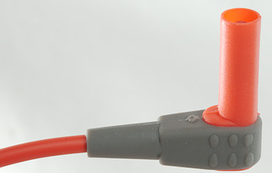
The shrouded plug is full size.
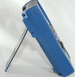
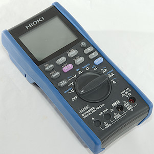
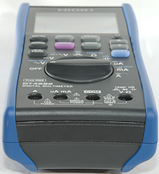
The range switch is fairly easy to turn and with this heavy meter it is stable both lying and standing. Due to the shutters plugs in the terminals can block the movement of the range switch.
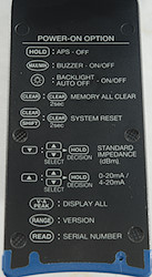
The meter has a couple of power on options (hold button down and turn on), some of them are saved (nice). To help remembering them the tilting bale has a list on the back.
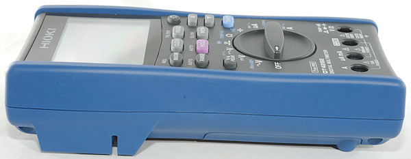
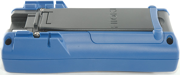
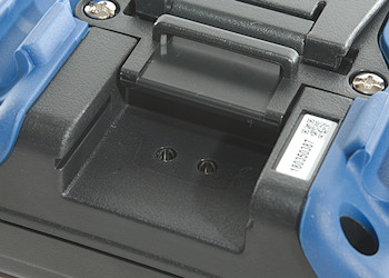
The computer interface is a small brick with a usb connector that is placed in this hole. The adapter is a bit expensive.
The serial number label can also be seen, this serial number was on the box and is coded into the meter and can be electronically read from the meter.
Display
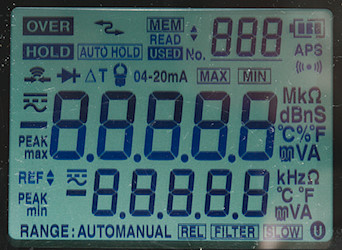
The above picture shows all the segments on the display, these are not shown on a normal power on, but using a power on option (VA PEAK), they can be shown.
The current clamp symbol is not used on this model.
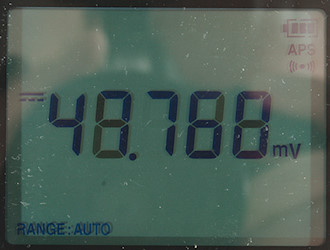
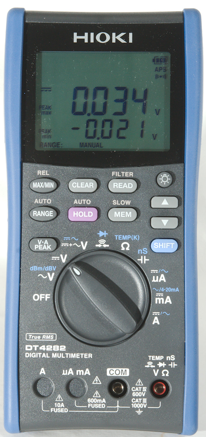
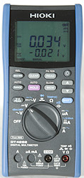
Typical display during usage, it will show the number and what measurement is selected.
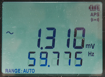
In AC ranges the frequency is shown on the secondary display.
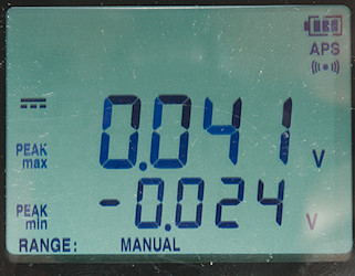
Some function will also use the secondary display.
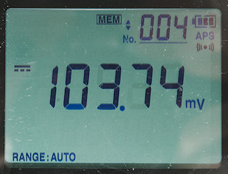
The memory uses its own counter on the display.
Secondary display functions (After / is small display):
- AC volt: VAC/frequency, dBm/frequency, dBV/frequency
- AC+DC volt: AC+DC/frequency, VDC/VAC
- Continuity: ohm/threshold
- Diode: volt/threshold
- uA mA A: ADC, AAC/frequency
- muA: ADC, AAC/frequency, %x-20mA
- A: ADC, AAC/frequency
- Peak: max/min
Functions
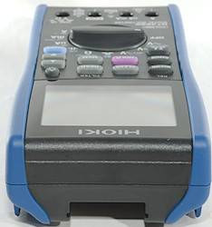
Buttons:
- Max/Min rel: Display maximum and minimum values, meter will always capture max/min values, this only shows the captured values. Hold down to store current value and show relative to this (Auto range is still active), hold down again to disable. In temperature the secondary display is used to show the reference value.
- Clear: Clear max/min/peak values or a memory location.
- Read/Filter: Recall memory locations, use up/down to select location, press read again to disable. Hold down to activate a LPF (Low pass filter) on VAC or AC+DC.
 : Turns on background light on/off.
- Range/Auto: Press to select manual ranging, press again to change range, hold down for automatic ranging.
- Hold (Pink): Freeze display reading, hold down for auto hold, i.e. meter will freeze any stable display reading.
- Mem/Slow: Saves the displayed values to memory, hold down to enable a averaging filter on values.

 : Arrow keys used to select memory number and to adjust some parameters.
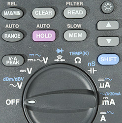
- VA Peak: Capture peak values in voltage and current modes, when this is active meter is in manual range.
- Shift (Blue): Select the ranges printed with blue.
Rotary switch:
- Off: Meter is turned off
- VAC: Show AC voltage and frequency, use the blue button to select dBm or dBV.
- VDC: Show DC voltage.
- VAC+DC: Show AC+DC voltage and frequency or both AC and DC at the same time.
 : Continuity and diode, on both the sensitivity can be adjusted with the arrows.
 : Resistance and temperature.
 : capacitance and conductance.
- uA: Current DC and AC. In AC the blue button will show frequency and duty cycle.
- mA: Current DC, AC and %x-20mA. In AC the blue button will show frequency and duty cycle.
- A: Current DC and AC. In AC the blue button will show frequency and duty cycle.
Input
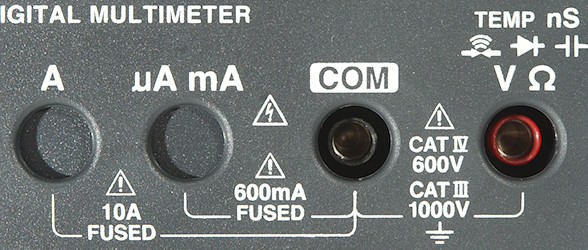
- 10A: High current.
- mAuA: The lower current ranges, the selector switch will change between two different shunts.
- CON: The common terminal for all ranges.
- xxx: All other ranges.
Measurements
- Volt and frequency
- At 10mVrms VAC frequency input range is from 1Hz to 460kHz
- At 100mVrms VAC frequency input range can be stretched to 500kHz that is maximum for meter.
- At 420mVrms AC+DC frequency input range works from 1Hz to 500kHz
- Max/min needs about 360ms to capture a voltage on DC.
- Peak needs about 0.3ms to capture a voltage with repeating pulses on DC (It either need a slightly longer pulse or a few pulses to capture the full voltage).
- Max/min is always active, using the max/min button will show the captured values. The button changes between max/min/actual.
- 1 VAC is 5% down at 190kHz, AC+DC is 230kHz (RMS will not work at the frequency).
- With filter (LPF) activated the range is locked to 600V & 1000V and I my generator do not have high enough output to test bandwidth
- Frequency counter will automatic be shown in AC ranges.
- Frequency input on AC do not require a zero crossing, on AC+DC the offset must be within about +/-5V
- In dBm the following impedance can be used as reference: 4, 8, 16, 32, 50, 75, 93, 110, 125, 135, 150, 200, 250, 300, 500, 600, 800, 900, 1000, 1200
- The AC+DC range has lower precision than the separate AC and DC ranges.
- On this meter it is important to stay above 5% (or at least 2%) of AC ranges, they will not show correct at very low values and may even show 0.
- Input impedance is 10..11Mohm on DC. VAC is a capacitor with 1Mohm after) and AC+DC is 1Mohm (This just about qualifies as a LowZ mode).
- The meter has a special polarity function that can be enabled (Setting is stored) and will give alarm every time a voltage at -10 volt or lower is measured.
- mV DC range is high impedance for DC up to around 1.5 volt where it drops to 10Mohm
- Frequency input on AC volt is 1Mohm.
- Over voltage protection is 1100VAC/DC
- Current
- Frequency counter will automatic be shown in AC ranges.
- On over current the digits and red background light will flash and there is an audible alarm if over current is high range of uA, mA or A setting.
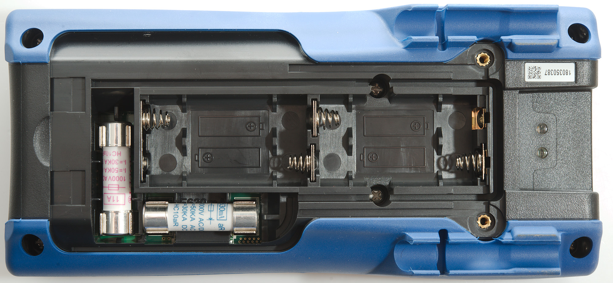
- 600mA current is protected by a 0.63A/1000V 10.3x38mm fuse.
- 10A current is protected by a 11A/1000V 10.3x38mm fuse.
- Ohm, Continuity, diode and capacitance
- Ohm needs about 1s to measure 100ohm
- Ohm is 0.9V open and 0.64mA shorted
- nS is 0.92V open and 0.1uA shorted
- Continuity is very fast (About 10ms).
- In addition to the buzzer continuity also flashes the red background light.
- Continuity has adjustable threshold: 20, 50, 100, 500ohm
- Continuity beeps when resistance is below selected threshold (It is very precise) and continues to beep until resistance is considerable higher.
- Continuity is 2.1V open and 0.64mA shorted
- Diode range uses 4.3V, max. display is 3.600V at 0.19mA, max. current is 1.0mA shorted
- Diode has adjustable threshold: 0.15, 0.5, 1.0, 1.5, 2.0, 2.5, 3.0V, buzzer and red light will be activated when voltage is below threshold.
- 10uF takes about 2.8 seconds to measure.
- 70000uF takes about 33 seconds to measure.
- Over voltage protection is 1000VAC/DC
- Miscellaneous
- Current consumption of meter is 16 to 23mA depending on range (AC, continuity and capacitance is 23mA), with backlight it is up to 42mA.
- Meter works down to 3.7V where it shows "Batt lo" and turns off, battery symbol flashes at 4.4V.
- Reading do not change with battery voltage.
- Backlight is stable until the meter turns off due to low battery.
- Meter has both a white backlight for lighting the display and a red backlight for notifying the user.
- The meter will often show the correct value in first display update.
- Viewing angle is good.
- Display updates around 5 times/sec
- Backlight will automatic turn off in about 40 seconds, this function can be disabled.
- Meter will go to standby in about 15 minutes and turn off in 45 minutes, this can be disabled.
- Standard probes fits perfectly.
- Weight is 647g without accessories, but with batteries.
- Size is 197 x 93 x 53mm.
- Probes
- Probe resistance 23mOhm for one.
- Probe wire is fairly soft and 90cm long.
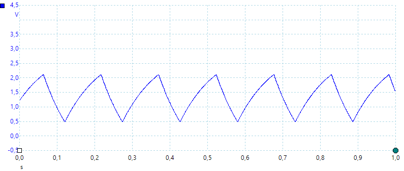
A look at the capacitance measurement waveform.
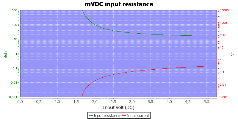
The input resistance in mVDC
Some AC ranges works down to 20Hz, but with lower precision.
The meter has a input impedance of 1Mohm in AC, this is nearly a permanent Low-Z (They are usual 0.3Mohm or lower).
Tear down
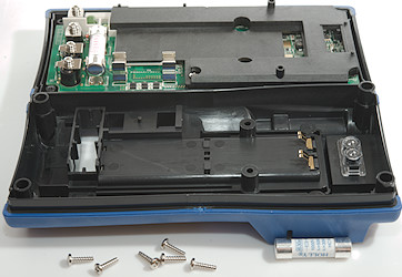
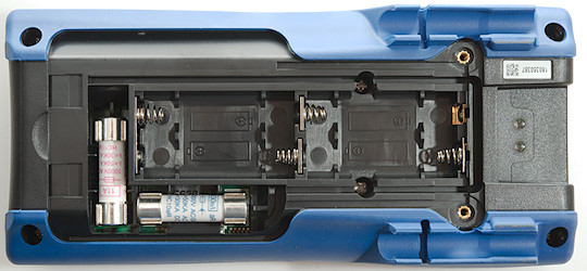
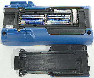
Six screws and the back could be removed, two of them are under the battery cover. It is necessary to remove one of the fuses to get the back cover up.
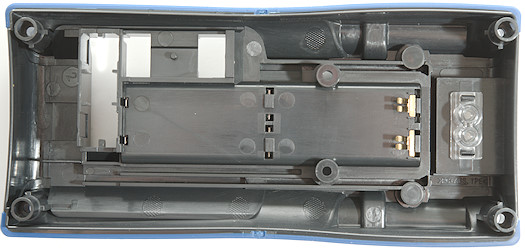
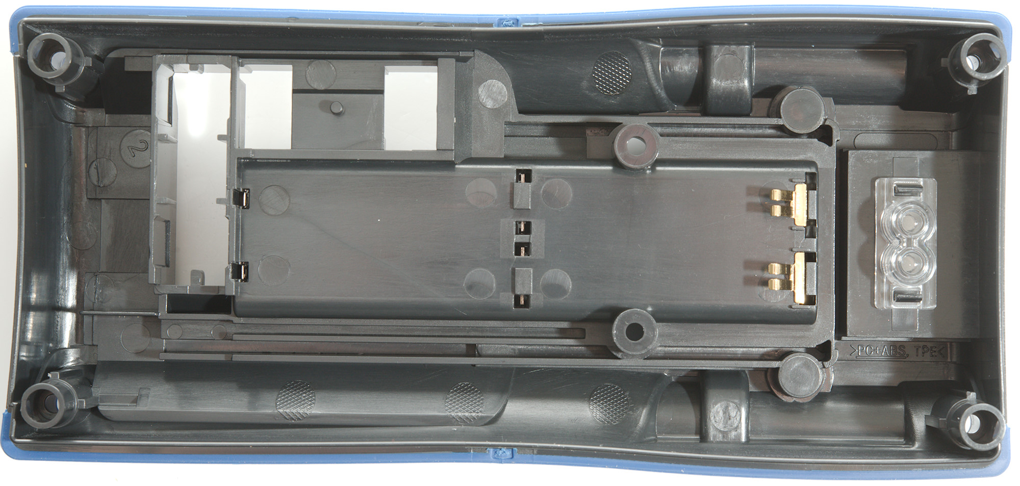
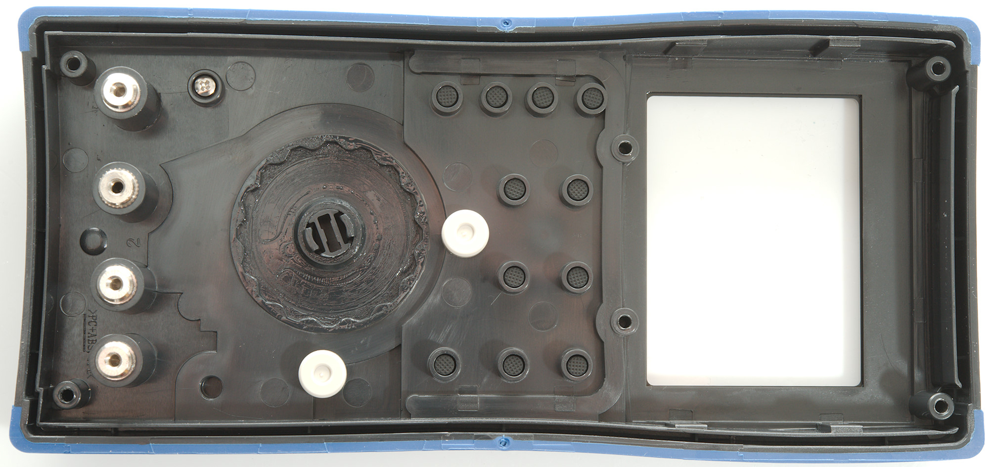
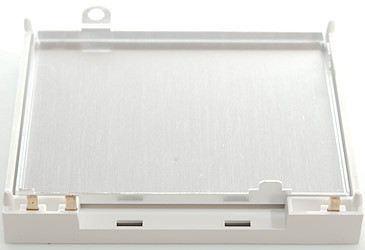
The battery box is part of the back cover with spring connections to the circuit board. There is also lenses for the opto communication.
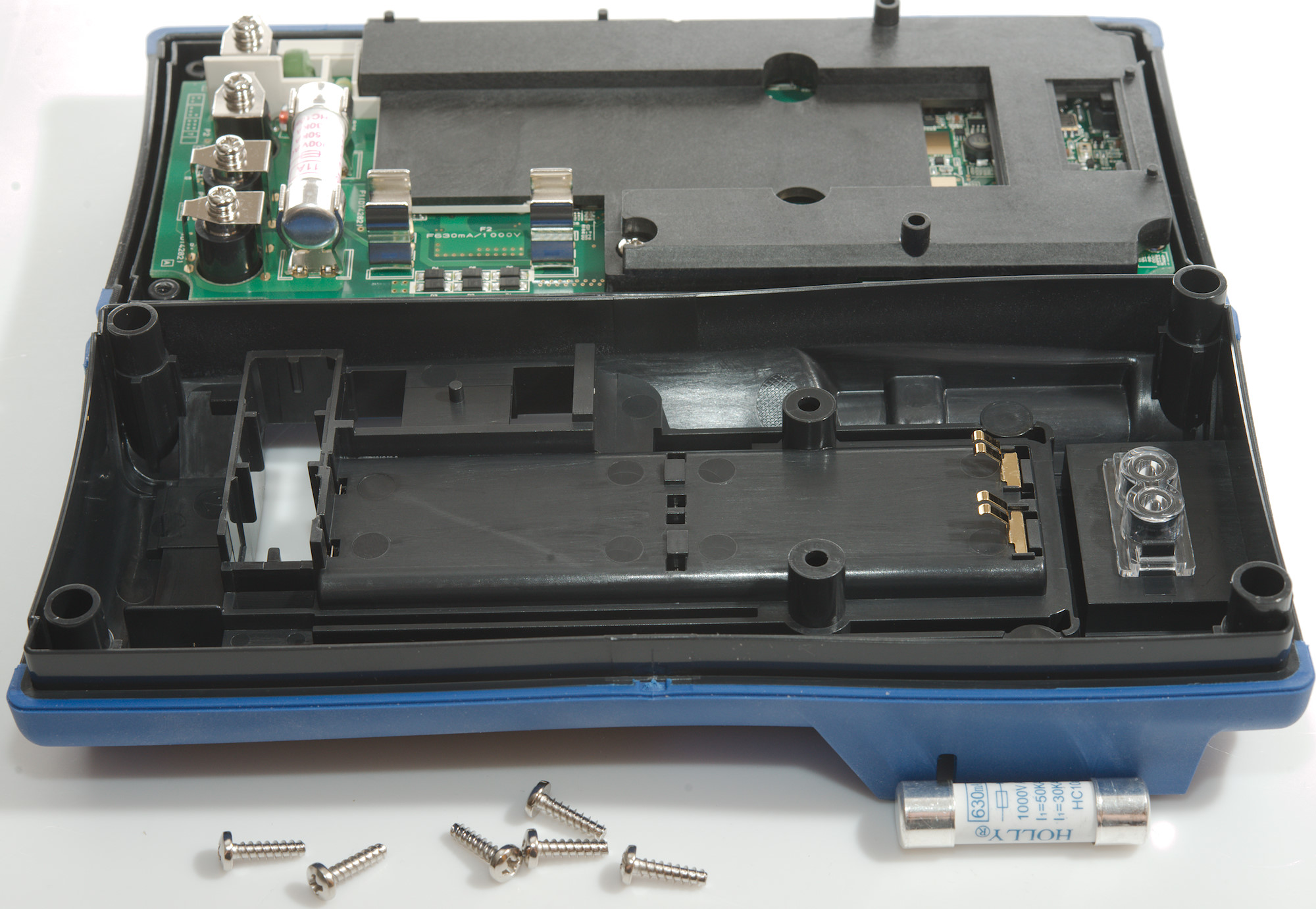
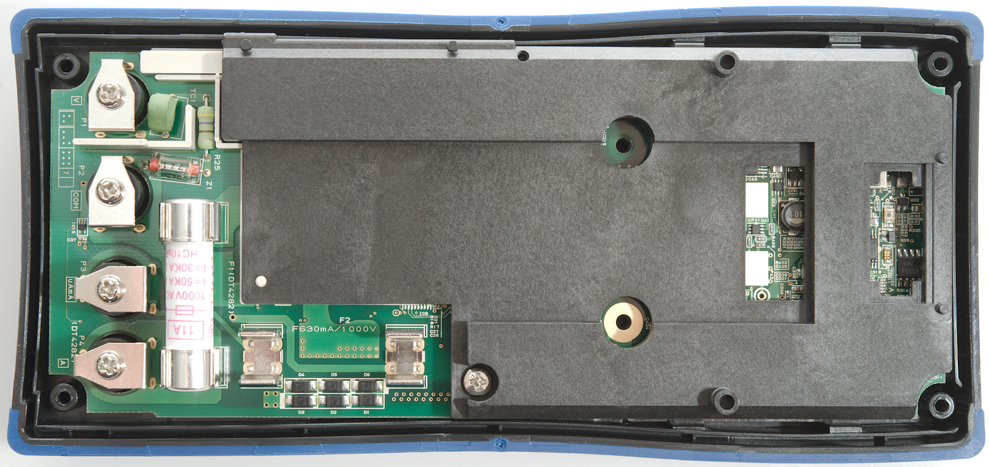
I did not really get to see much, there is a secondary cover.
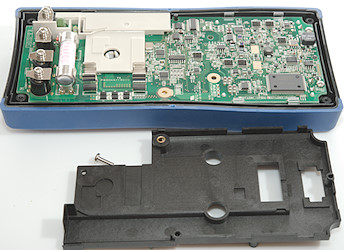
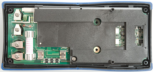
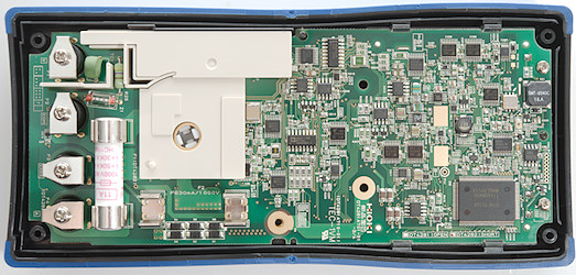
I only had to remove one screw to remove it (This screw holds all the internal covers), but there are more internal covers.
The internal cover is conductive plastic, pressing two probes into it gives about 600-1000ohm at any distance.
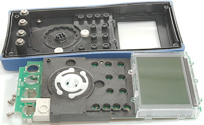
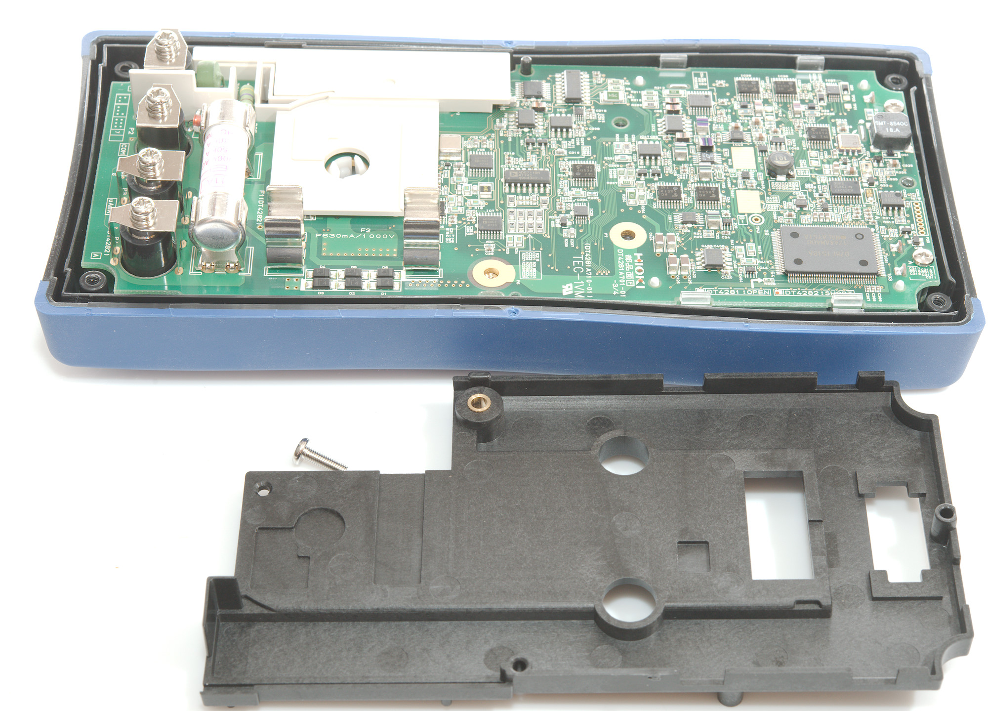
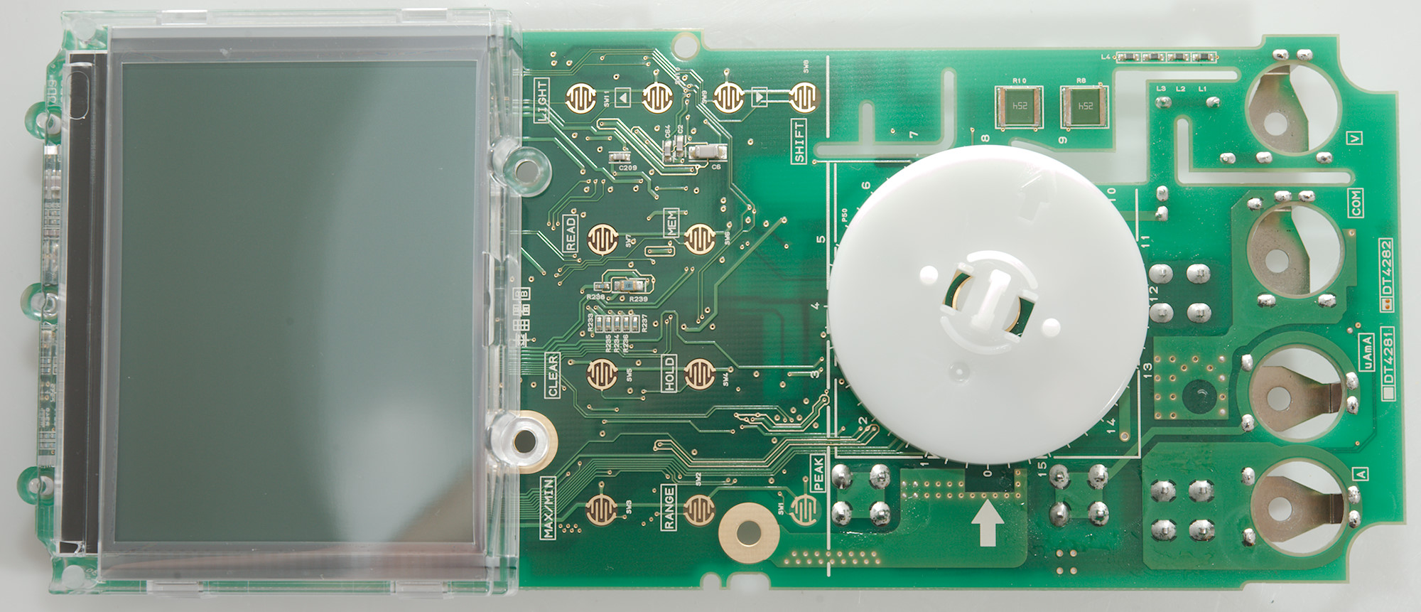
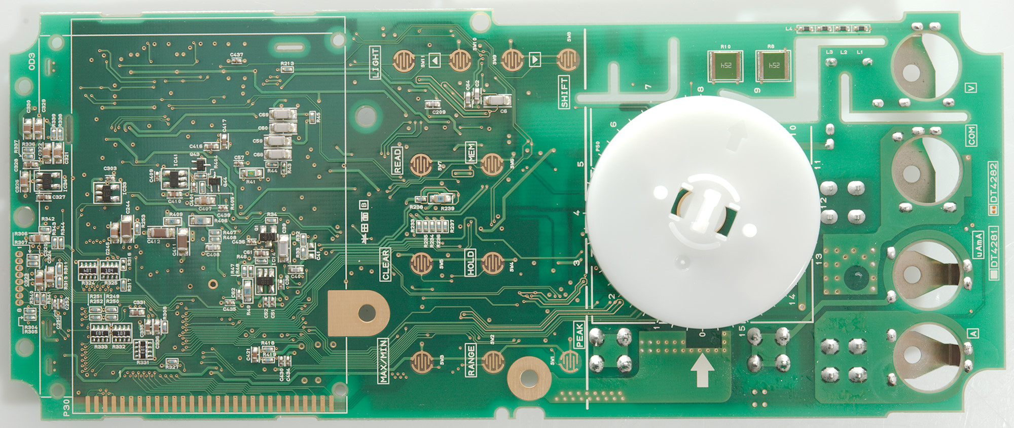
Removing the screws on the terminals allowed my to take the circuit board out.

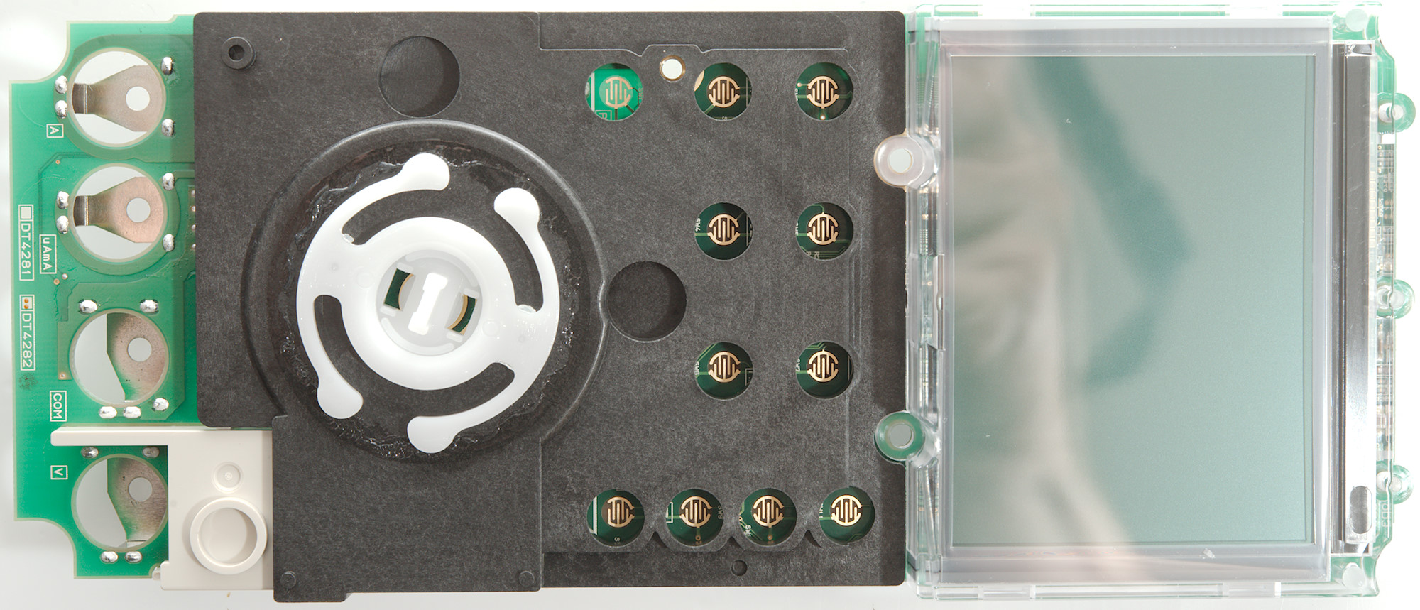
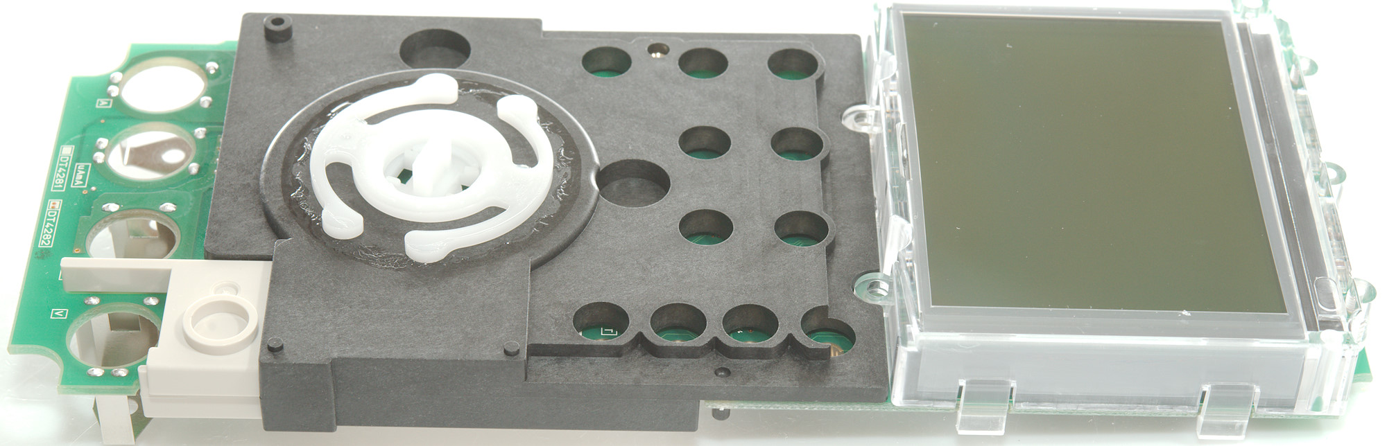
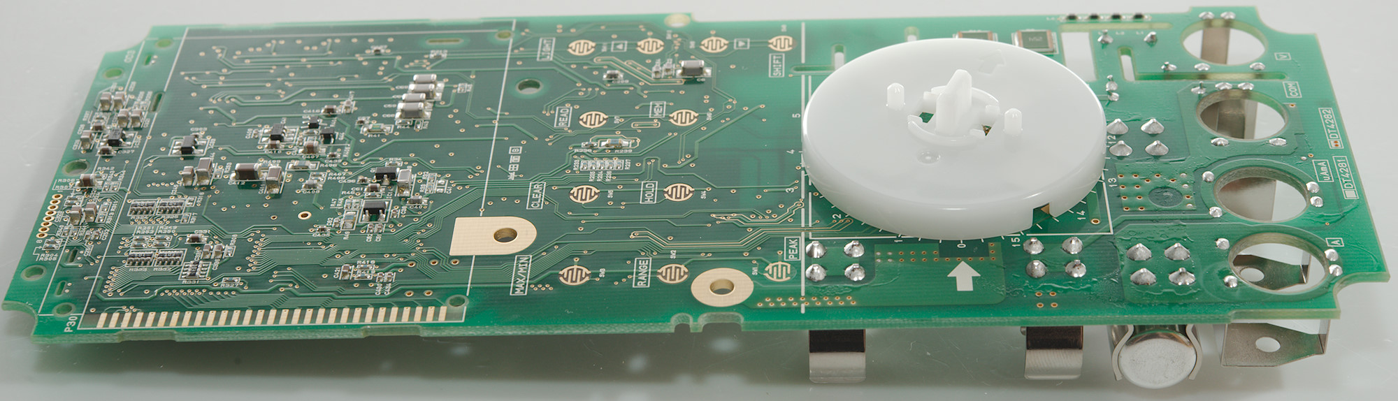
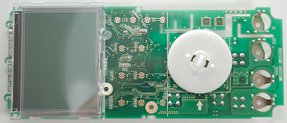
The other side of the circuit board also has internal covers.

But they are loose now.
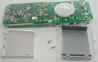
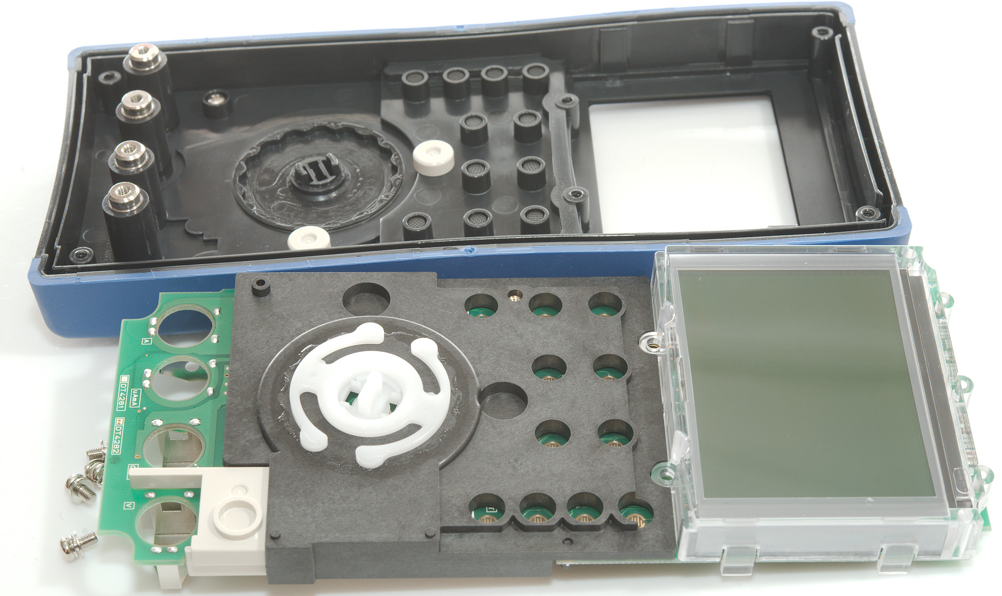
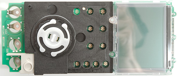
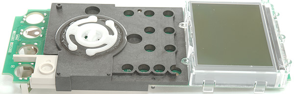
The display was mounted with two screws and the backlight was soldered to the circuit board.
The backside of the backlight is shielded and it has 3 connections (red + white led and common).
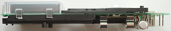
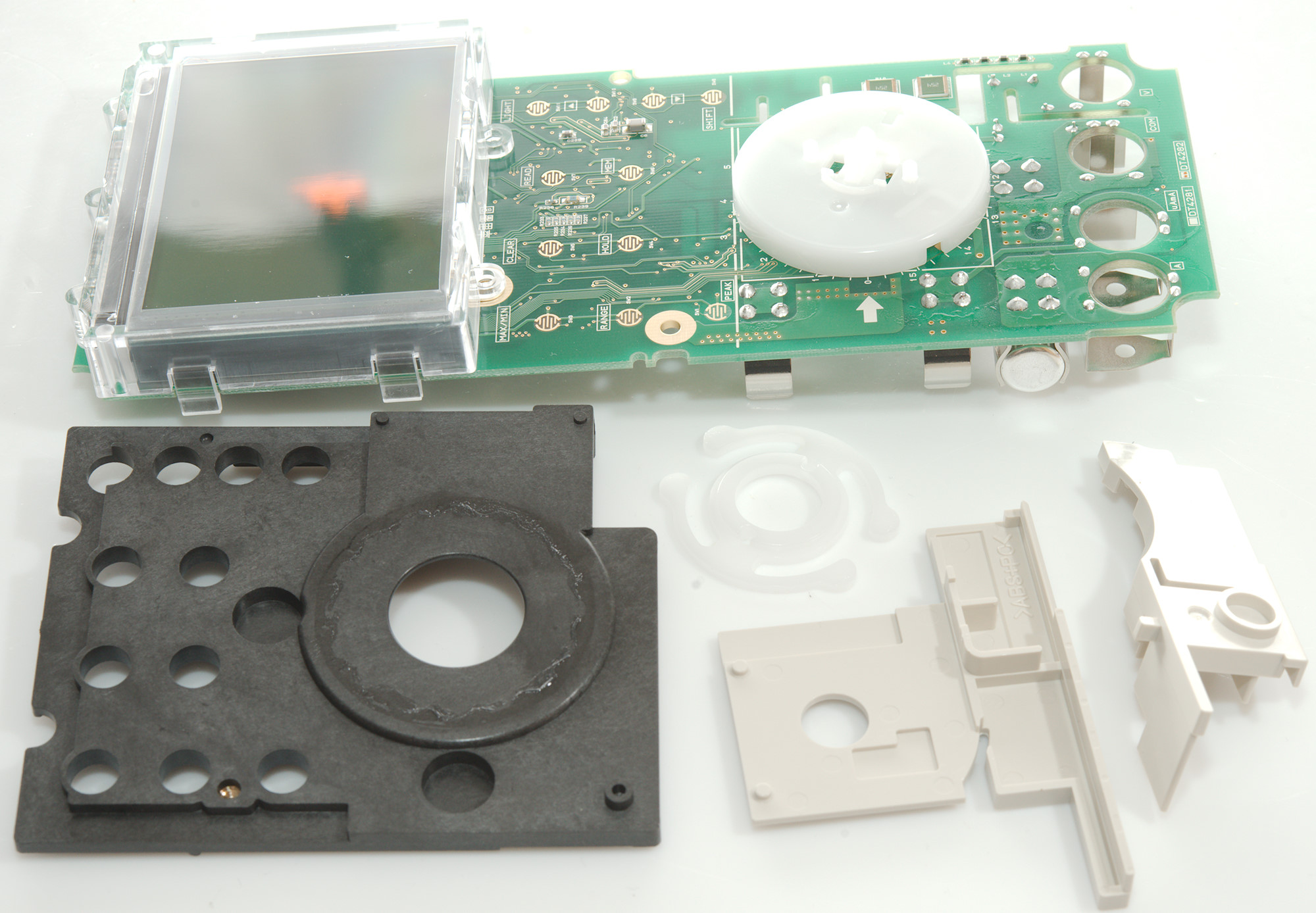
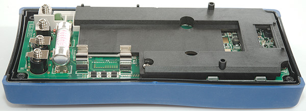
The circuit board and all the internal covers are one unit and can be removed when unscrewed from the terminals (This image is from when I put it together again).
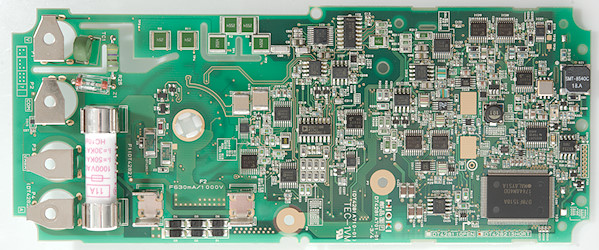
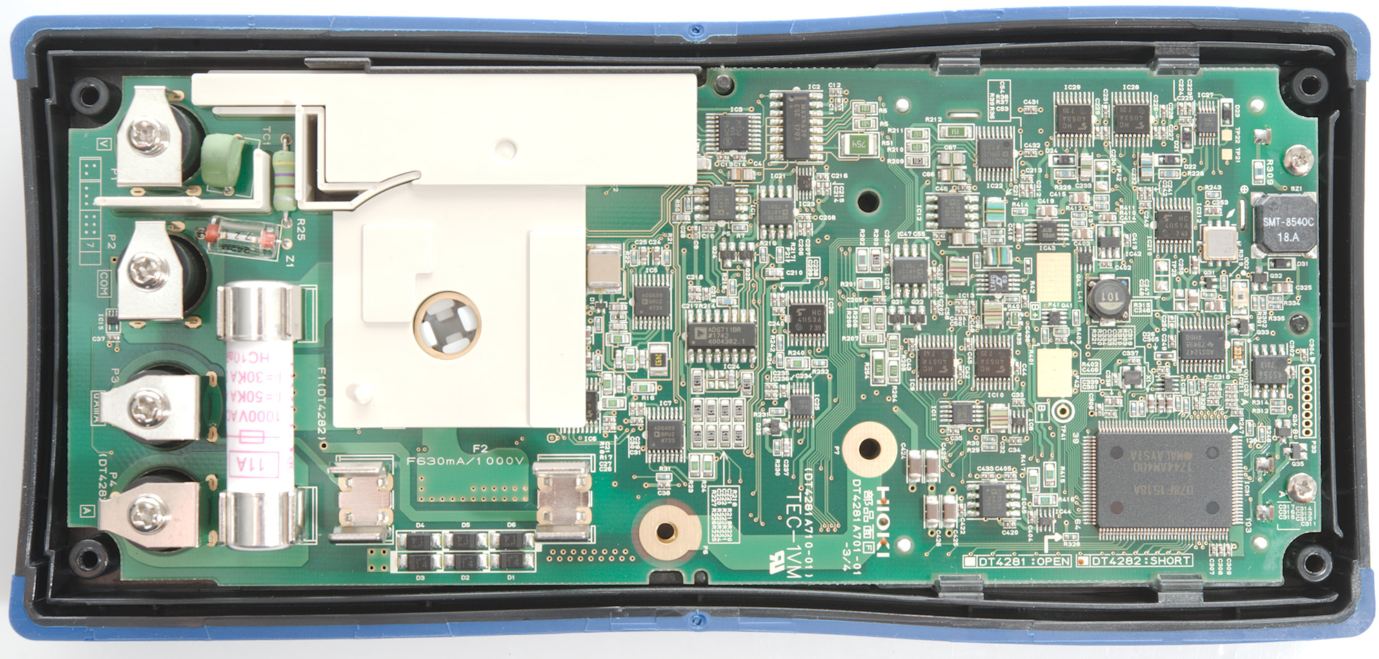
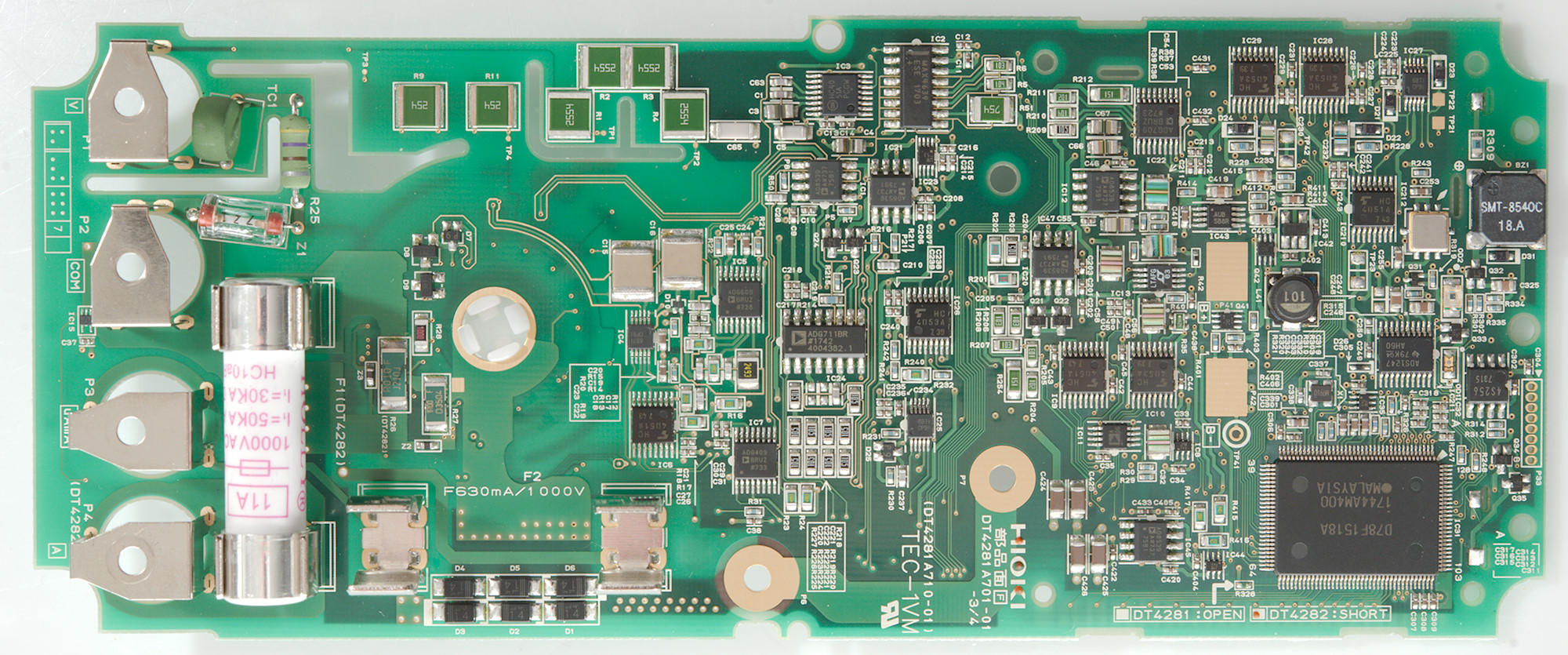
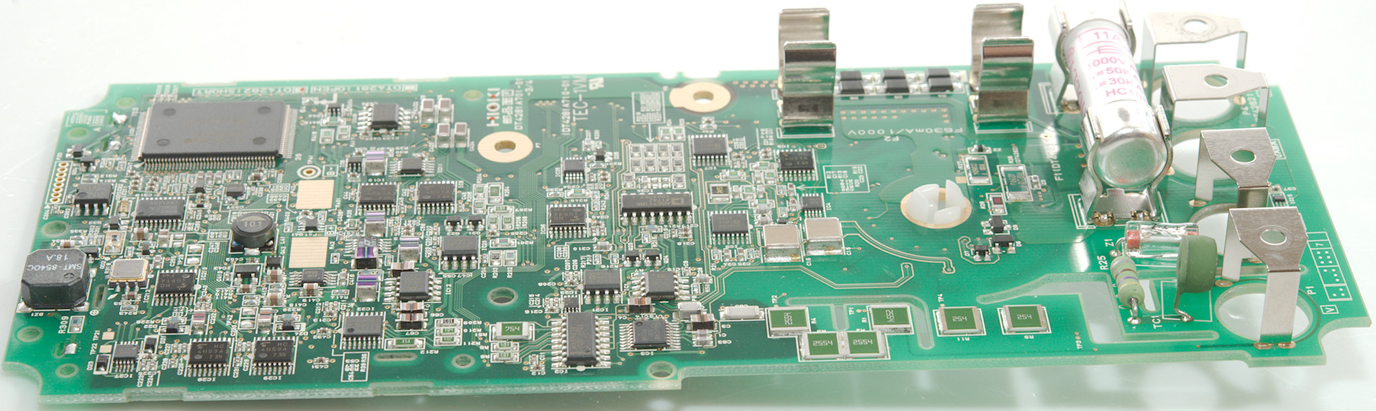
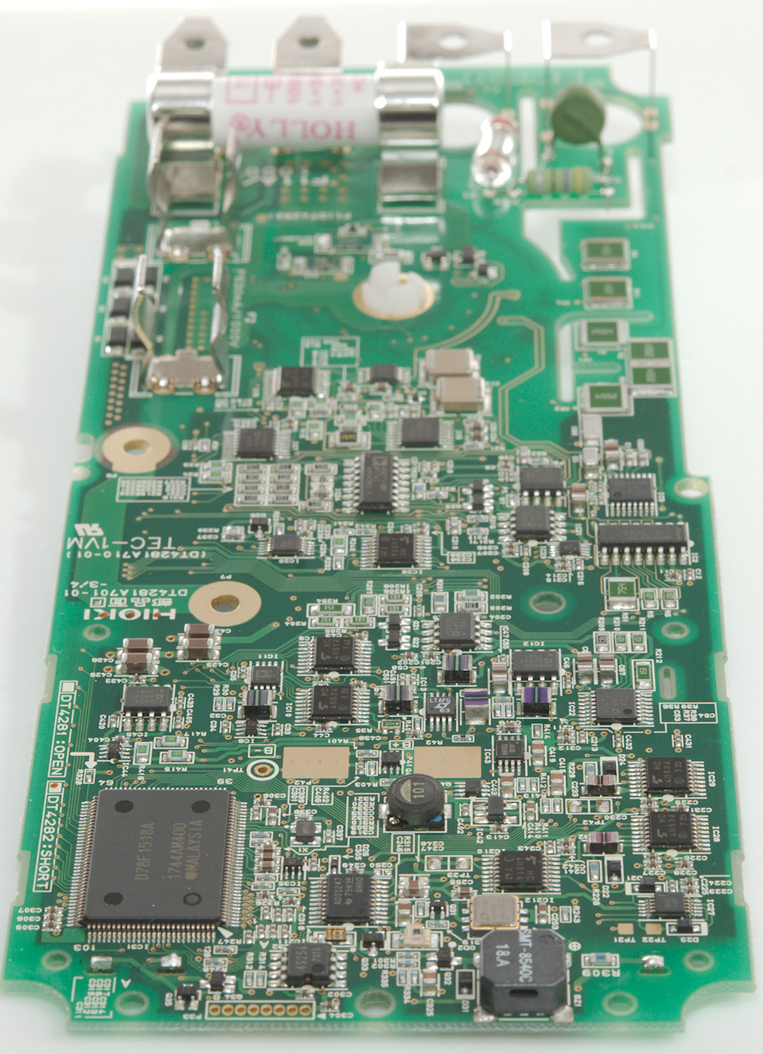
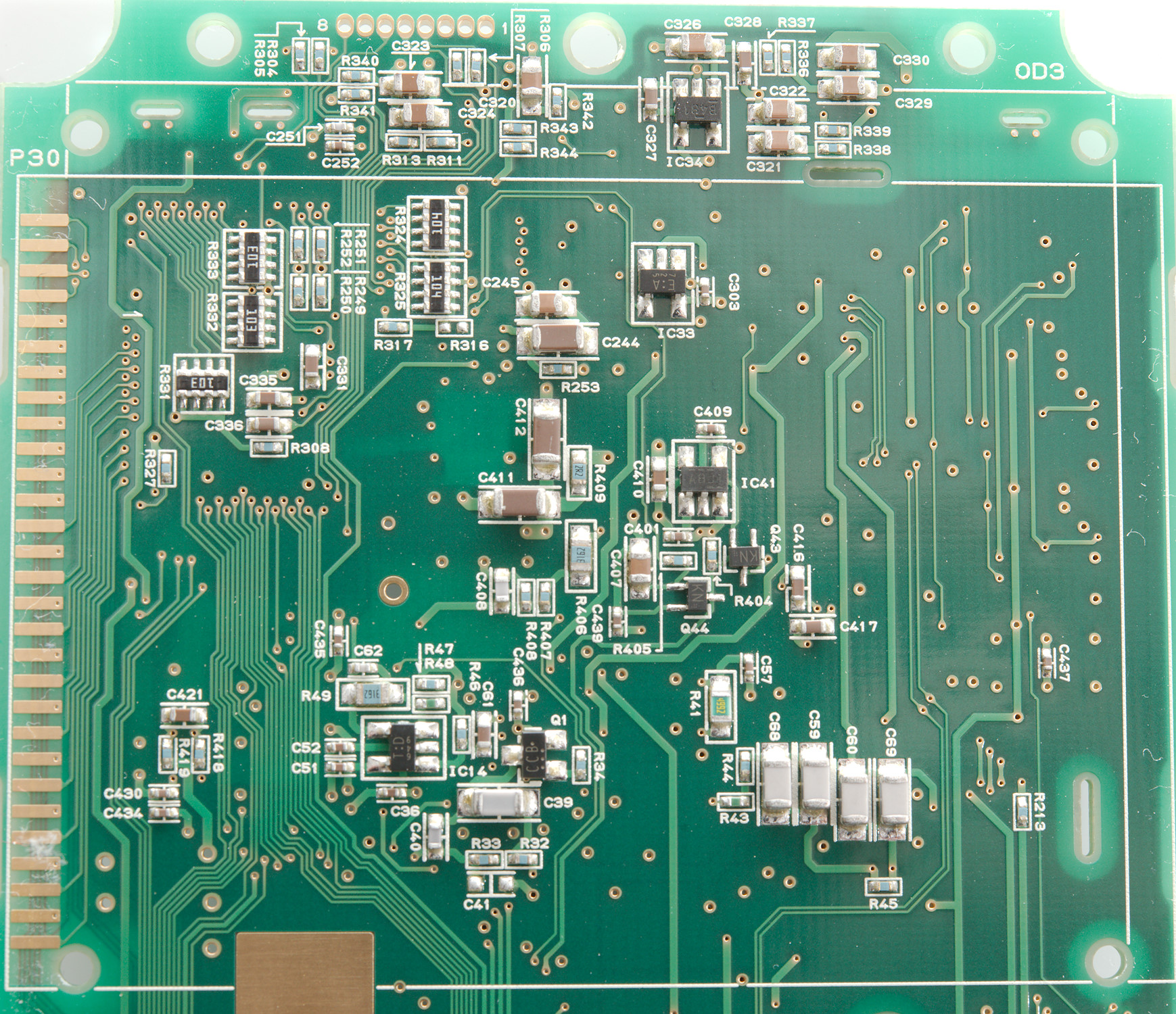
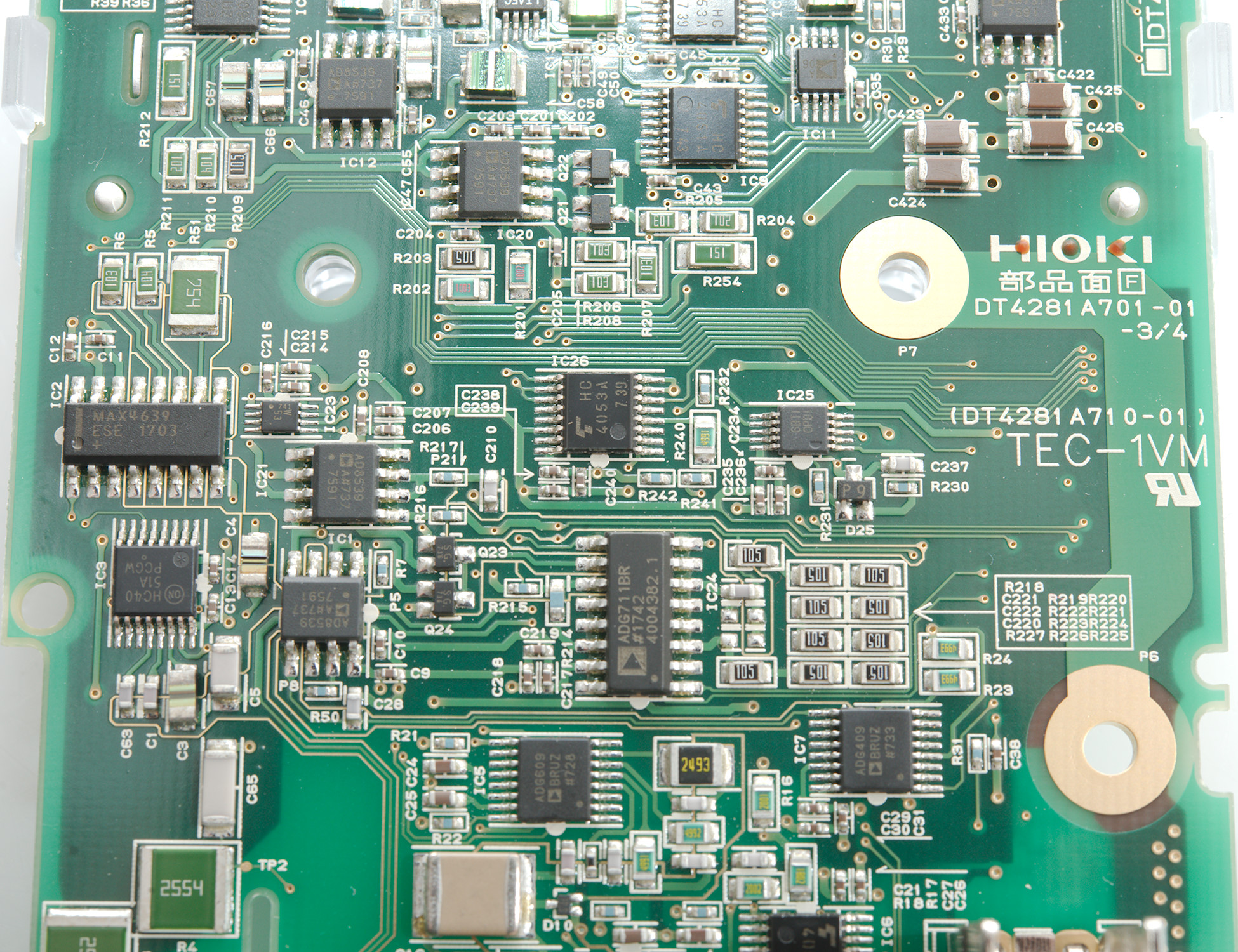
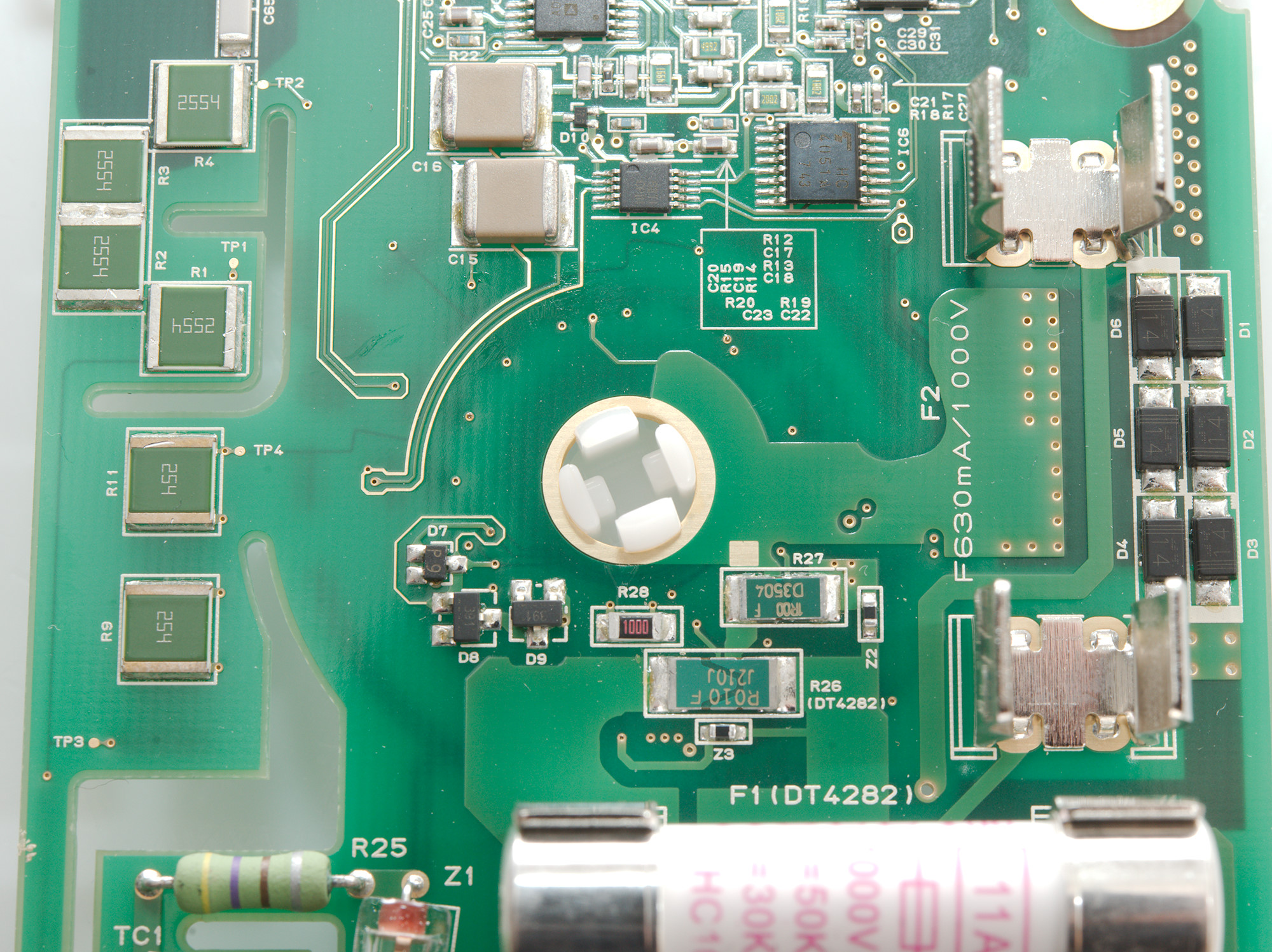
The current input do not use the common 10A wire shunt, but a regular smd resistor (R26: 0.01ohm), the mA (R27: 1ohm) and uA (R28: 100ohm) is just next to it. The protection diodes (D1..D9) is mounted next to the mA fuse. The voltage input is also a bit uncommon with only a single PTC with series resistor (R25: 470ohm) and a spark gab (Most meters has dual paths with PTC's). This meter do not use protection on the 10Mohm (R1..R4: 4x2.55Mohm) or 1Mohm (R8..R11: 4x250kOhm) paths, but has some fairly large resistors for it.
An interesting detail is all the gold traces, they are guard traces, i.e. placed around sensitive areas and kept at the same voltage usual with an OpAmp, this means very low leakage current from the sensitive area.
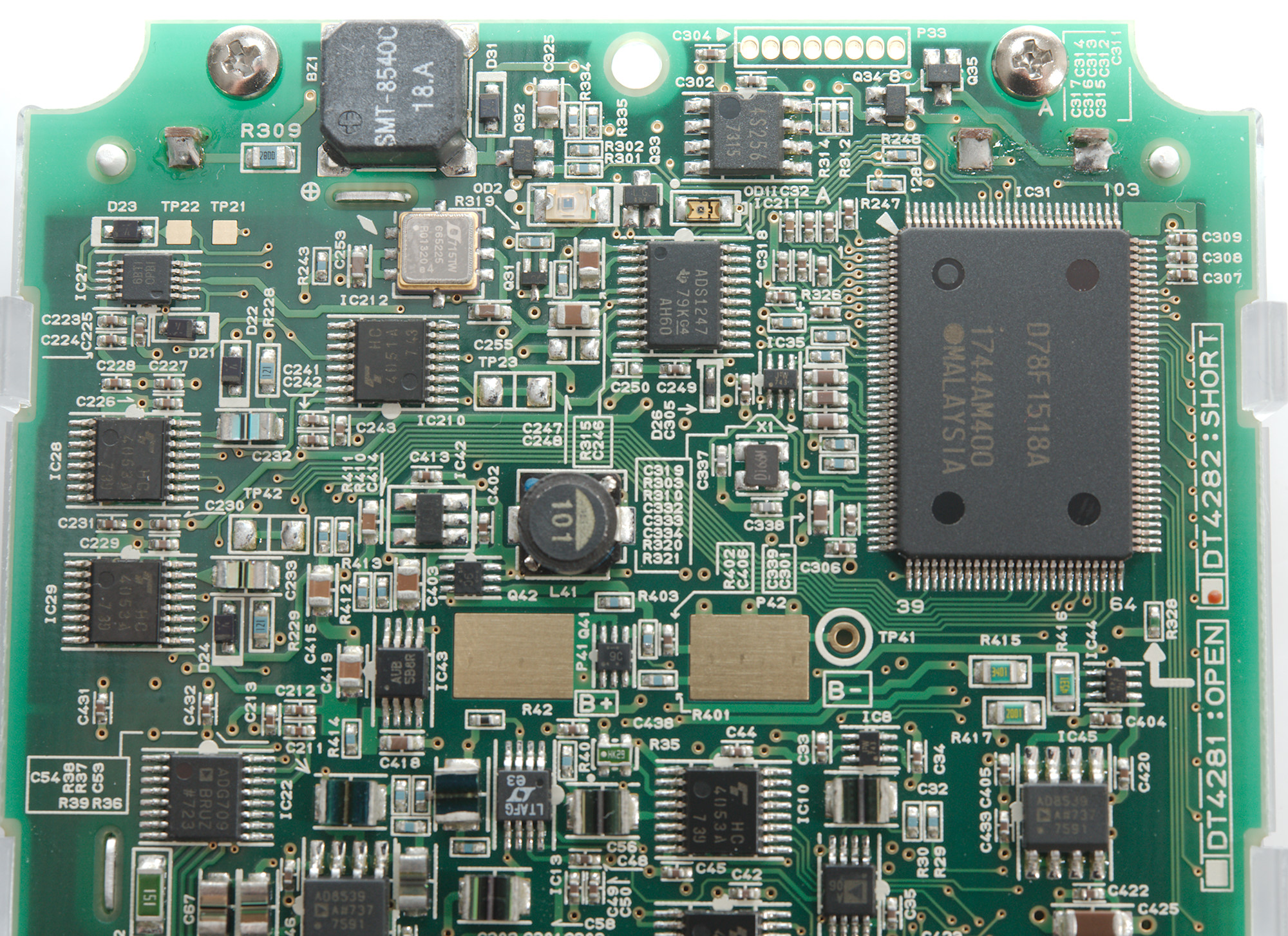
Most of the range switching must be electronic, the meter is packed with analog switches: IC1: AD8539, IC3: 4051, IC5: ADG609, IC6: 4053, IC7: ADG409, IC21: AD8539, IC24: ADG711, IC26: 4053 and more. I did also see some OpAmps IC1: AD8539, IC12: AD8539, IC20: AD8539
The big chip (IC31) is probably a UPD78F1518A 16 bit microcontroller and next to it is a 24bit ADC (IC211: ADS1247). The RMS converter is from LT (IC13: LTAFG/LTC1968)
The above list of chips is not complete, it is fairly complicated to build a high-end meter without using a multimeter chipset.
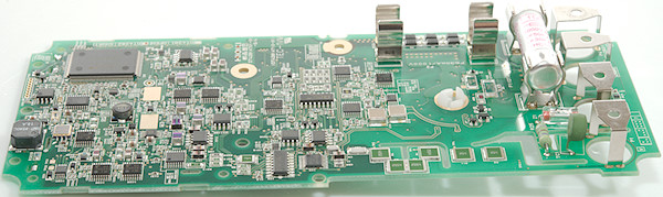
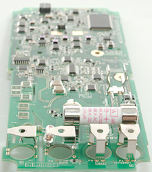
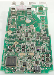
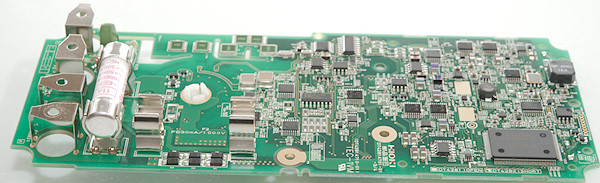
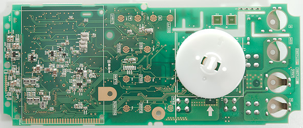

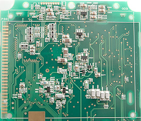
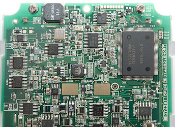
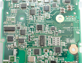
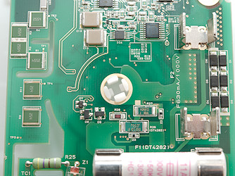
The above 4 images are for people that want more detailed pictures of the circuit board (Most chip numbers can be seen on them).
Conclusion
This meter is a high-end meter with many functions and very good precision, I also expect the CAT rating is correct. The functions generally works very fine and fast, but I found a few limitations: LPF can only be used on 600V & 1000V range, I am missing duty cycle and average (In some cases the filter function can substitute) and I do not know how useful 400 memory locations are.
The user interface is slightly different to most other multimeters with min/max always active and a CLEAR to reset both min/max and peak without disabling them.
I like the meter, user interface and how fast it is.
Notes
How do I review a DMM
More DMM reviews