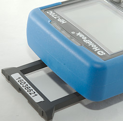
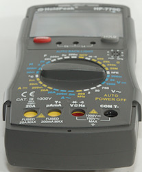
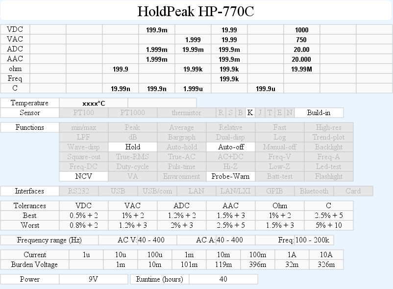
DMM HoldPeak HP-770C
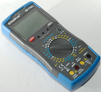
This is a fairly cheap DMM with 40000 count display and lot of functions.
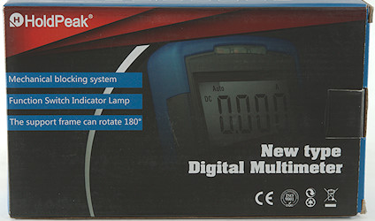
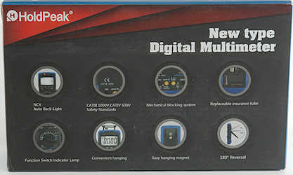
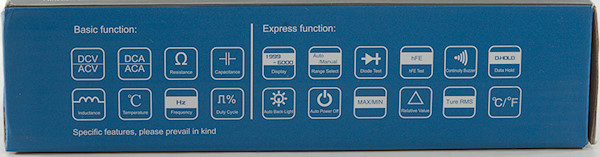
It arrived in a universal HoldPeak cardboard box.
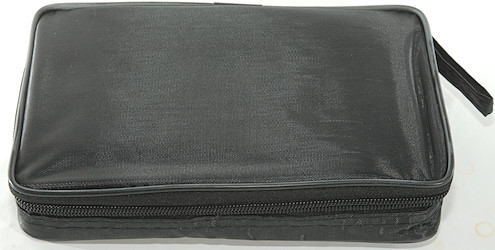
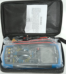
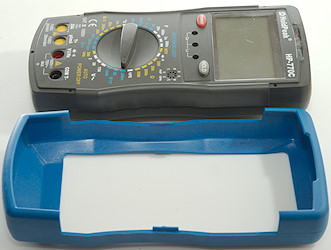
Inside the box was a pouch with everything inside.
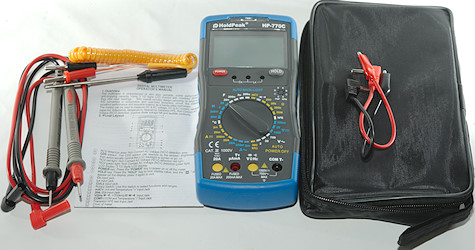
It included the DMM, a pair of standard probes, a pair of alligator clips probes, a thermocoupler, a instructions sheets and the pouch.
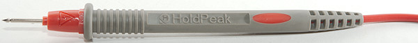
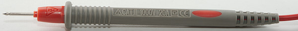
No tip covers on these probes that is rated for 1000V Cat III and 20A
This means the rating is wrong.
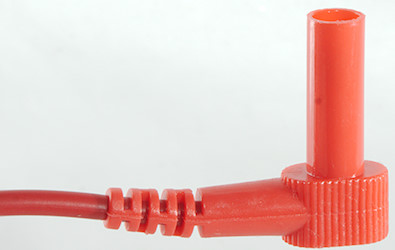
The plug is fully shrouded.
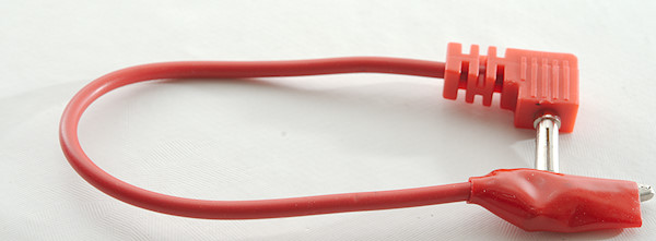
The alligator clip probes are without shroud and fairly short because they are designed to be used with the LC test function.
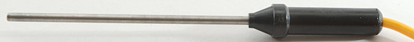
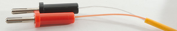
The thermocoupler is encapsulated, this makes it useful for inserting in stuff, but not as good for measuring surface temperatures.
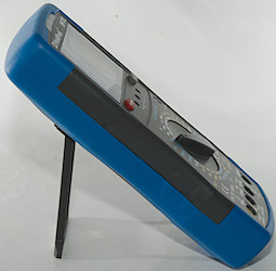
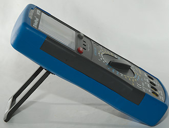
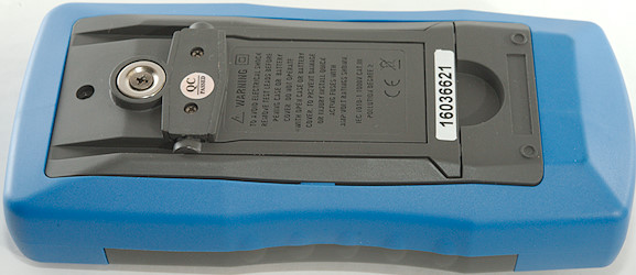
The tilting bale has multiple position, including one as a hanger.
On a smooth surface the meter needs two hands to turn the range switch.
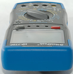
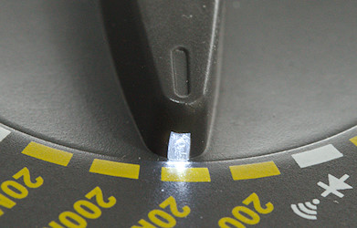
There is light in the range switch, it turns on together with the backlight.
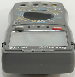

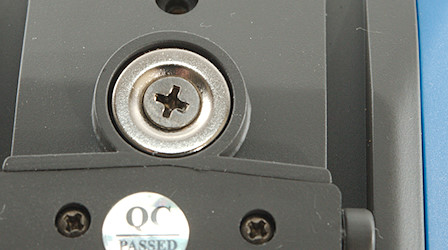
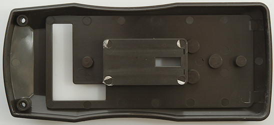
The metal ring on the back is a magnet, i.e. it is possible to attach the meter to metal surfaces.
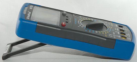
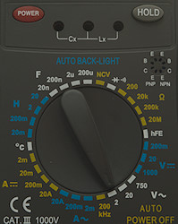
Display
The meter do not show all display segments when turned on.
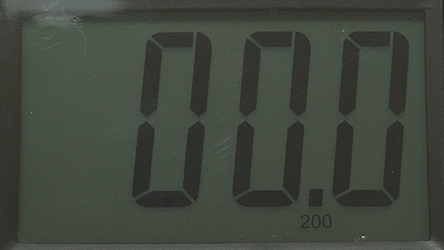
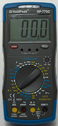
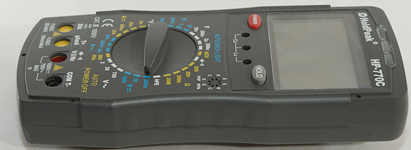
Display during normal usage, it will show selected range and value.
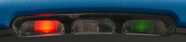
At the top is two leds used for the NCV, green when no field detected and red when a field is detected. The center position is a photosensor used to turn on the backlight on the display and the light in the range switch.
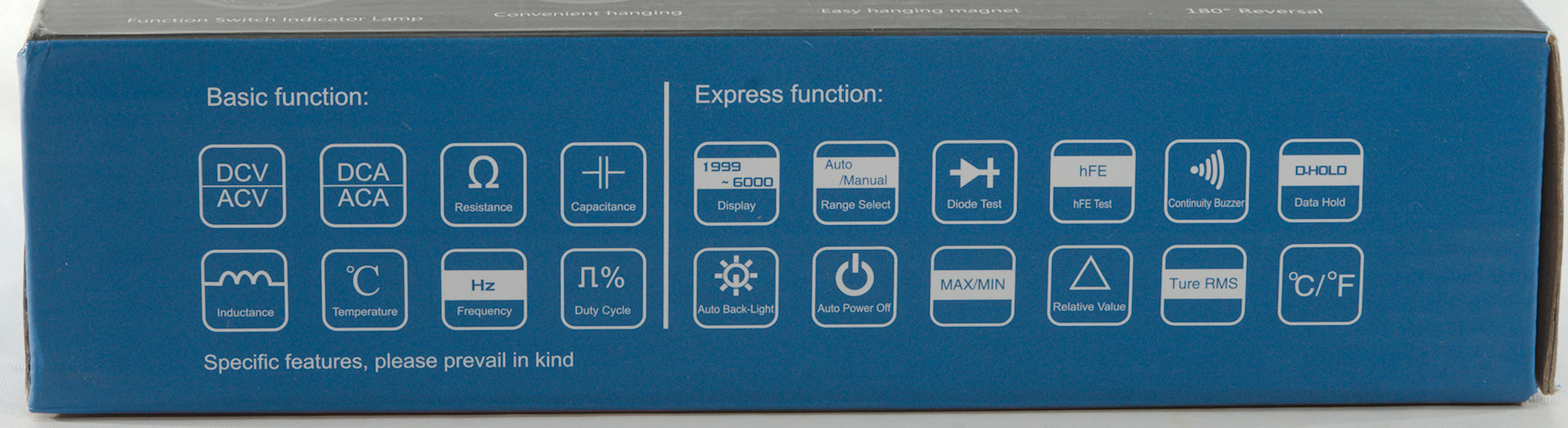
Functions
Buttons:
- Power: A regular switch to turn the power on/off, must be used to recover from a automatic power off.
- Hold: Freezes the display.
Rotary switch:
- NCV: Non-contact voltage or electric field detection.
 : Diode/Continuity, it is a 2K range with buzzer at low resistance.
 : 4 ohm ranges
- hFE: Transistor tester.
- VDC: 3 volt DC ranges.
- VAC: 3 volt AC ranges.
- 200kHz: Frequency counter range.
- AAC: 3 AC current ranges.
- ADC: 4 DC current ranges.
- °C: Temperature range.
- H: 4 inductance ranges, use the top connectors.
- F: 4 capacitance ranges, use the top connectors.
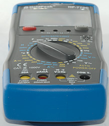
Input
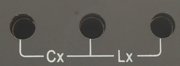
The capacitance and inductance input connectors. The are used with 4mm banana plugs.
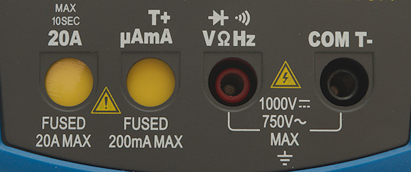
- 20A: High current, maximum is 20A for 10 seconds.
- mAuA: The milliampere ranges and temperature.
- xxx: All other ranges.
- COM: The common terminal for all ranges.
The shutters secures mostly that only the correct inputs are accessible, the capacitance and inductance are not covered by shutters.
Measurements
- Volt and frequency
- Frequency counter will count as long as the voltage goes within 7V of COM positive or negative.
- At 1Vrms input frequency range is 0.2kHz to 199kHz
- 1 VAC is 5% down at 8.2kHz.
- Input impedance is 10-11Mohm on DC and AC (2VAC is 1Mohm)
- mV DC input impedance drops above 3V, from 10Mohm to about 1Mohm
- Frequency input is high impedance below 8 volt, then it drops to 2kOhm
- Rated overload protection is 1000VDC and 750VAC
- Current
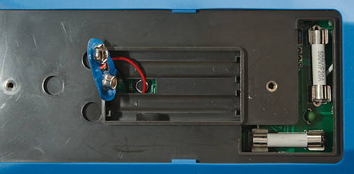
- Fuse on mA is 200mA/500V 6x30mm
- Fuse on A is 20A/500V 6x30mm
- 20A for up to 10 seconds.
- Ohm, Continuity, diode and capacitance
- Ohm needs about 1.2s to measure 100ohm, manual range makes it fast.
- Ohm is 3.0V open in 200ohm range and 0.5V open in other ranges and 1.5mA and down to 0.05mA shorted
- Continuity is very slow (About 400ms).
- Continuity beeps when resistance is below 67ohm, display shows resistance and is a 2k range.
- Diode/Continuity range uses 3.0V, max. display is 1.999V at 1.4V and 0.7mA, max. current is 1.3mA shorted
- 10uF takes about 0.6 seconds to measure.
- 190uF takes less than 2 seconds to measure (A too high value is shown in 5 seconds).
- Inductance is generally fast to measure, that means below 1 second
- Rated overload protection on is 500V DC/AC
- Miscellaneous
- Current consumption of meter is mostly 7.5mA, 9mA in ohm and 12mA in NCV (24mA with backlight)
- At about 3.8V meter will show overload, it turns off at about 2.2V, battery symbol show at 6.6V.
- Reading are stable down to 4.3 volt, below that it will be a bit random and very wrong.
- Backlight brightness depends on battery voltage and is dim at 3.2V
- Viewing angle is good.
- Display updates around 2.5 times/sec
- The meter usual need a couple or more display update to reach the final value.
- Backlight is controlled by ambient lightning, i.e. it turns automatic on.
- Will automatic report low battery in about 8 minutes and a minute or two later turn off the meter.
- Standard probes can be fully inserted.
- Weight is 346g without accessories, but with rubber sleve and batteries.
- Size is 194 x 88 x 45mm with rubber sleeve and battery.
- Probes
- Probe resistance 38mOhm for one.
- Probe wire is fairly soft and 85cm long.
- Resistance for alligator clip is 18mOhm for one.
- Wire for alligator clip is 15cm long.
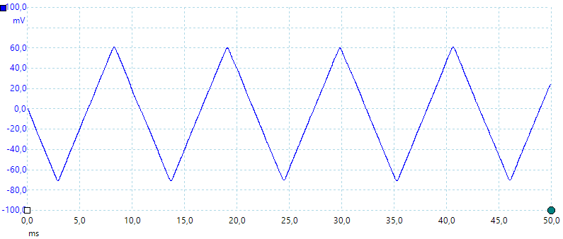
A look at the capacitance measurement waveform when measuring 1uF.
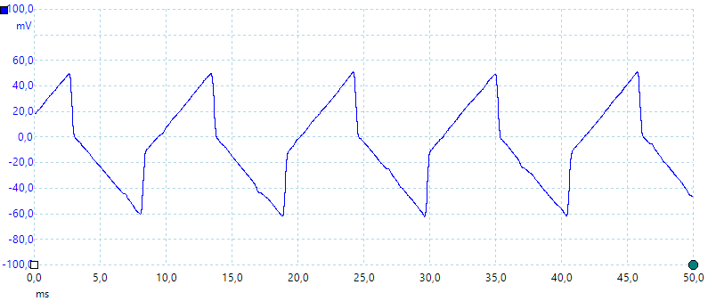
Here is the inductance measuring waveform, the frequency is about the same on all inductance ranges.
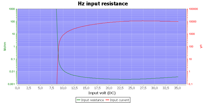
Frequency input resistance.
When input voltage contains both AC and DC, the DC readout will be too low.
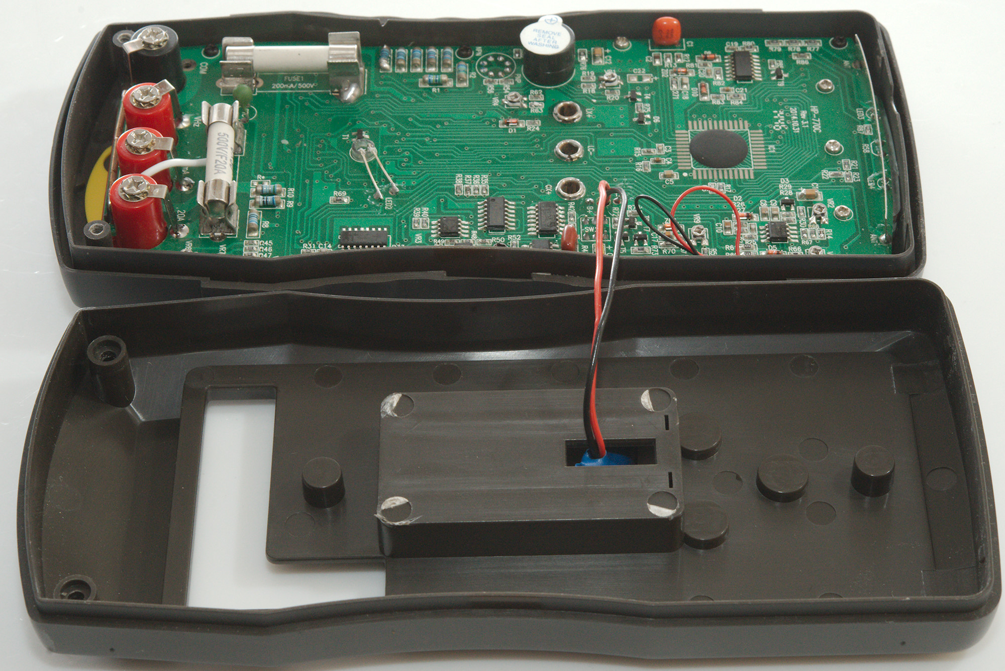
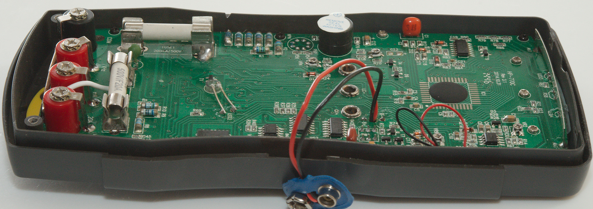
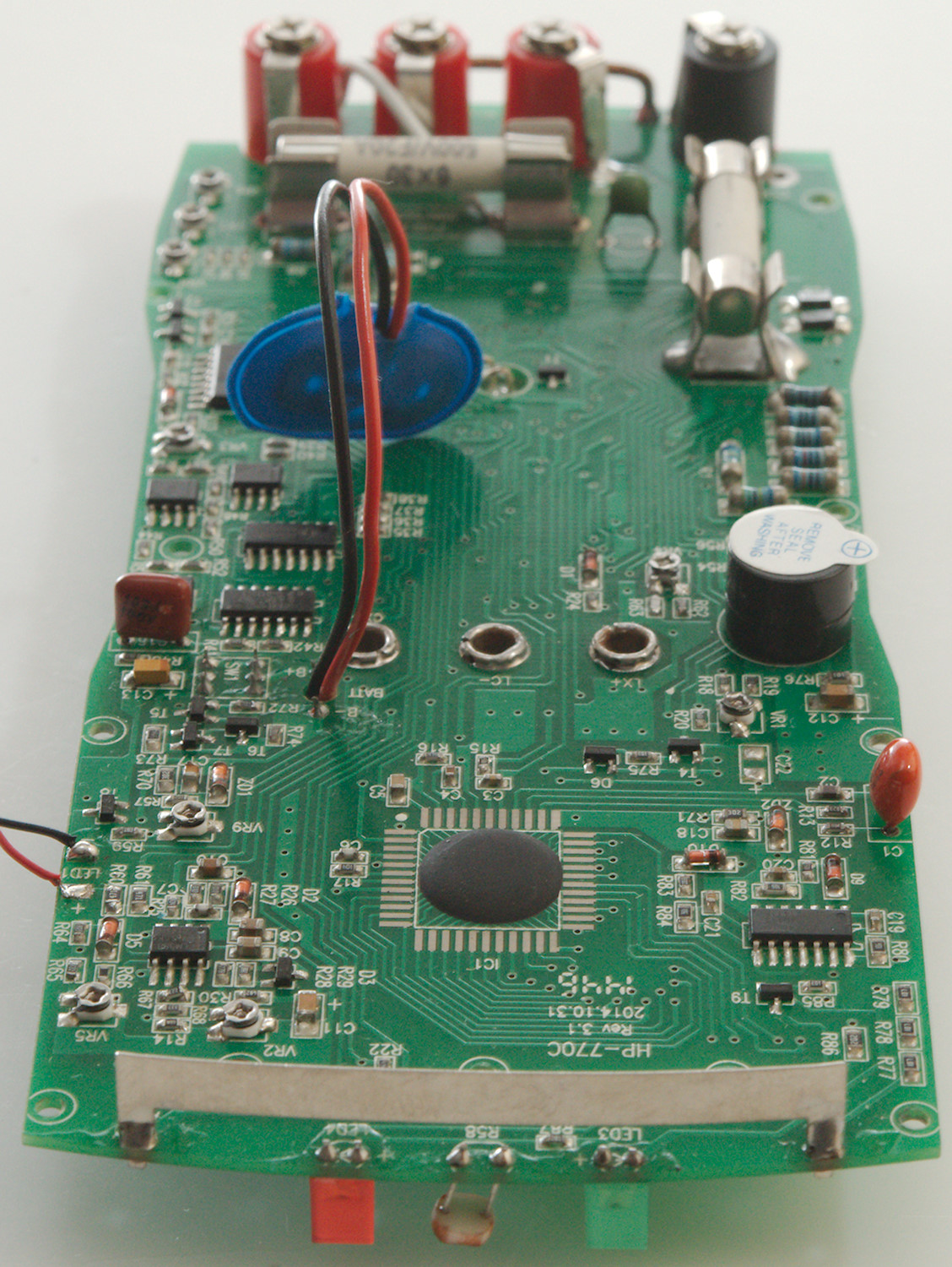
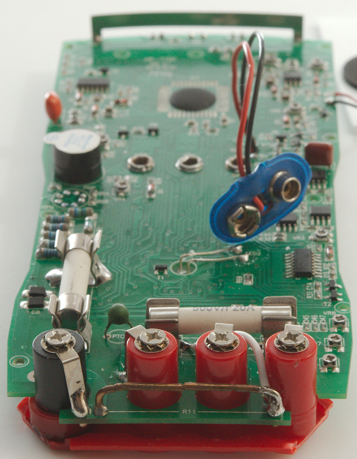
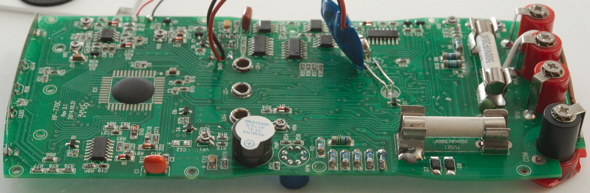
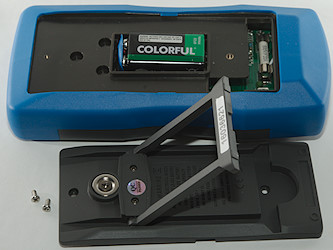
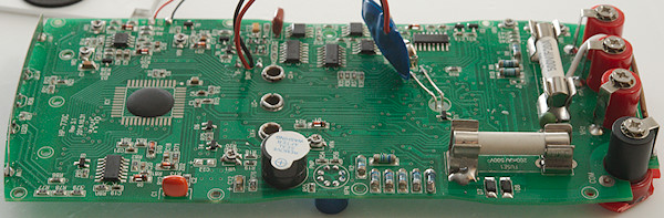
Tear down
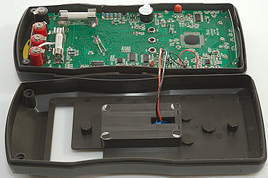
I had to remove two screws to open the DMM.
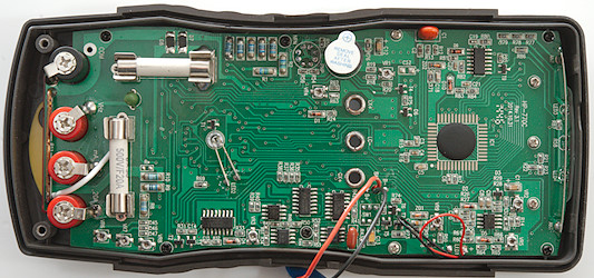

To remove the circuit board there was 6 more screws.
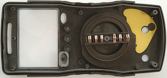
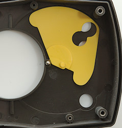
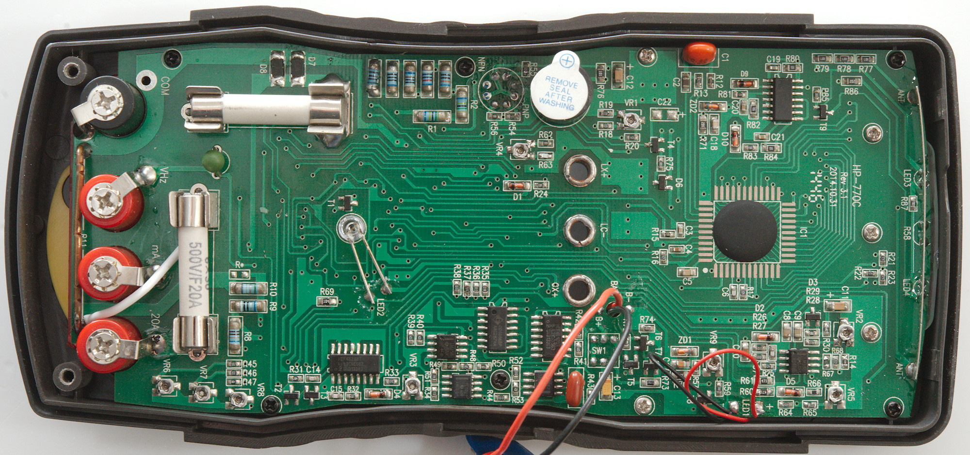
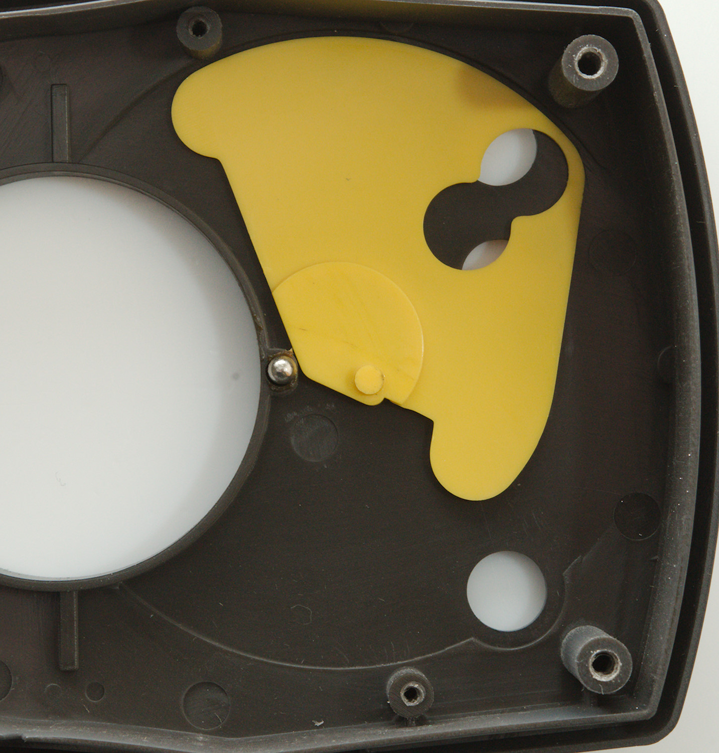
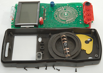
The shutter is controlled by a track on the range switch.
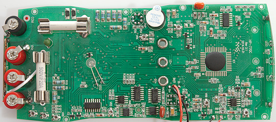
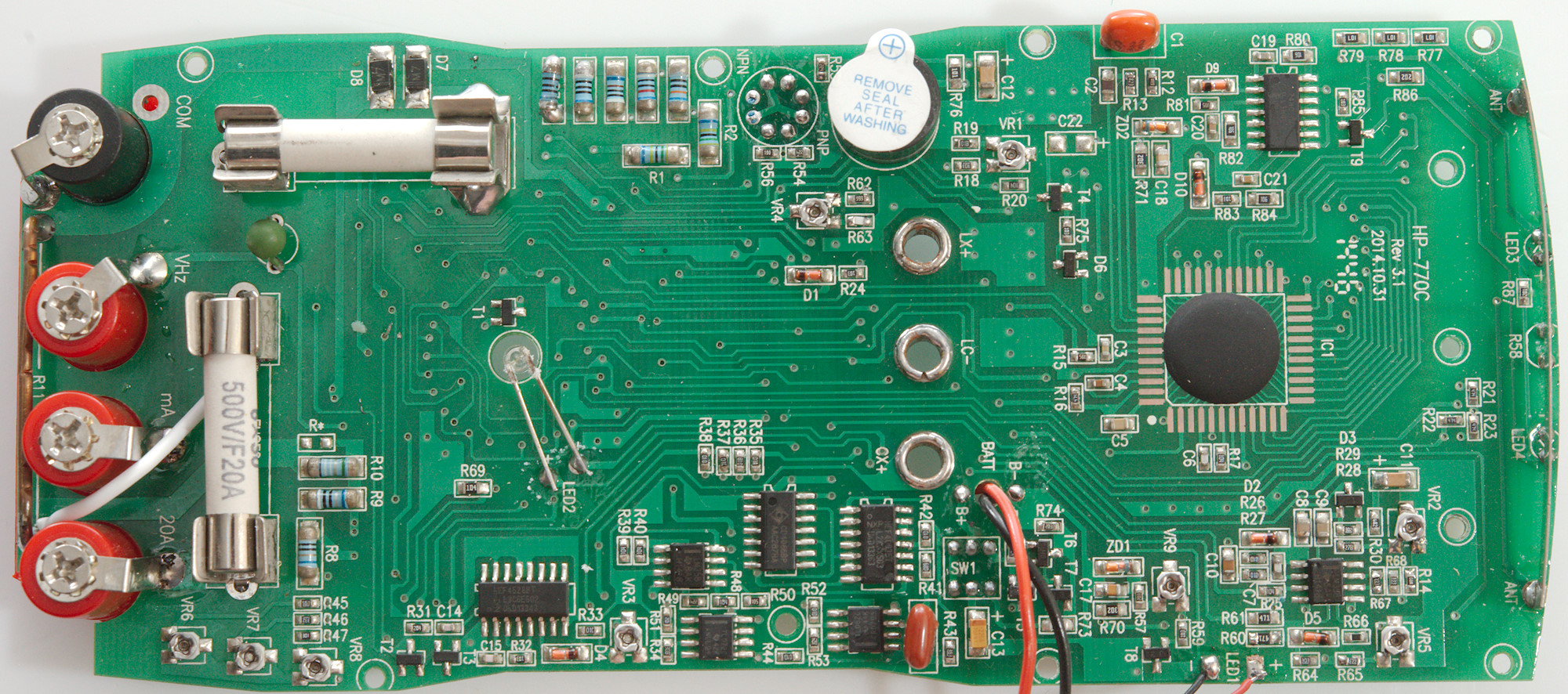
This meter has a lot of chips, many of them are OpAmps: 2xLM358, TL062, TL072, a analog switch (4066), some Schmitt triggers / gates (7414, 4093) and a dual timer (4528).
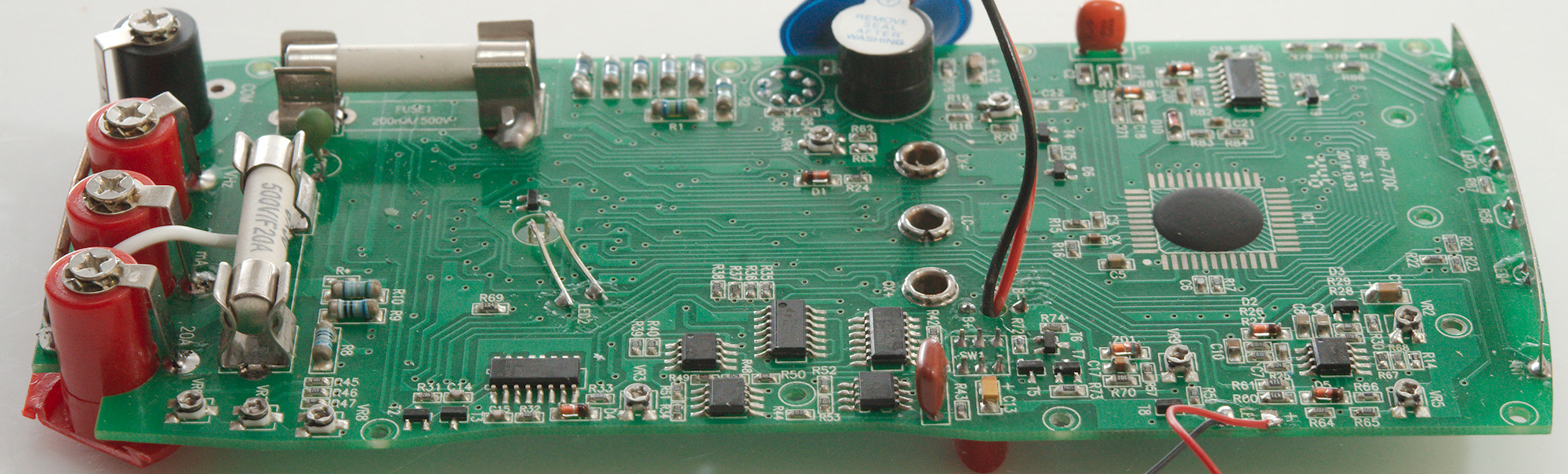
The current shunts are near the 20A fuse (R10: 1ohm, R9: 9ohm, R8: 90ohm), there is two diodes to protect the current shunts (D7 & D8).
The 200kHz frequency range use the PTC and the transistor pair (T2 & T3) for protection, then the signal is going through a resistor and capacitor into the timer. This probably means that a analog voltage proportional to the frequency is generated and the meter measures that voltage to show frequency (Not very precise). Ohm output current is secured with the PTC and some transistors (T5, T6, T7). The voltage 10Mohm input is two resistors (R1 & R2: 2x4.5Mohm). The inductor measurement use some of the OpAmps and probably also the other chips.
There are many trimpots on the board to calibrate it.
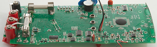

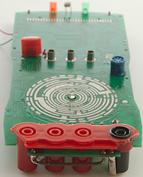
At the end of the circuit board is the NCV antenna, this an external part. There is 3 resistors (R77, R78, R79: 3x10Mohm) to maintain the potential on it.
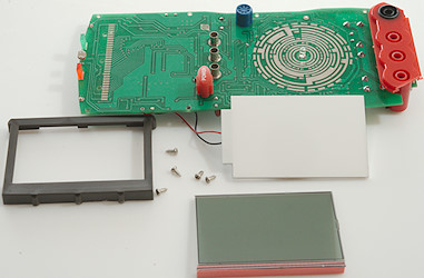
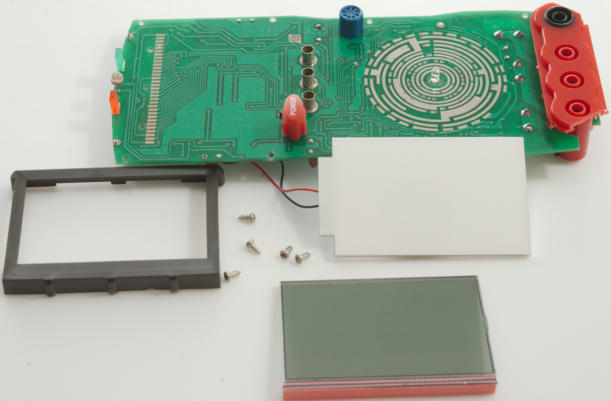
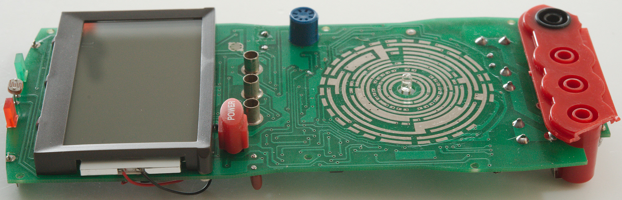
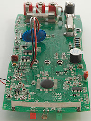
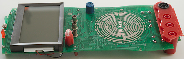
I had to remove 5 screws more before I could remove the display.
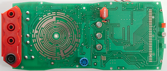
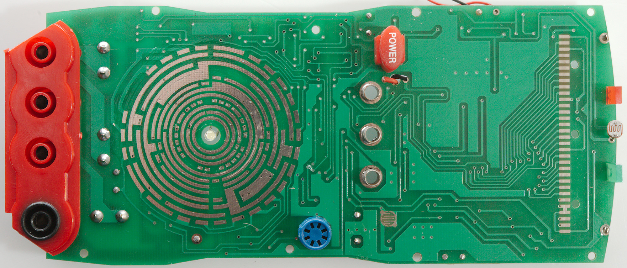
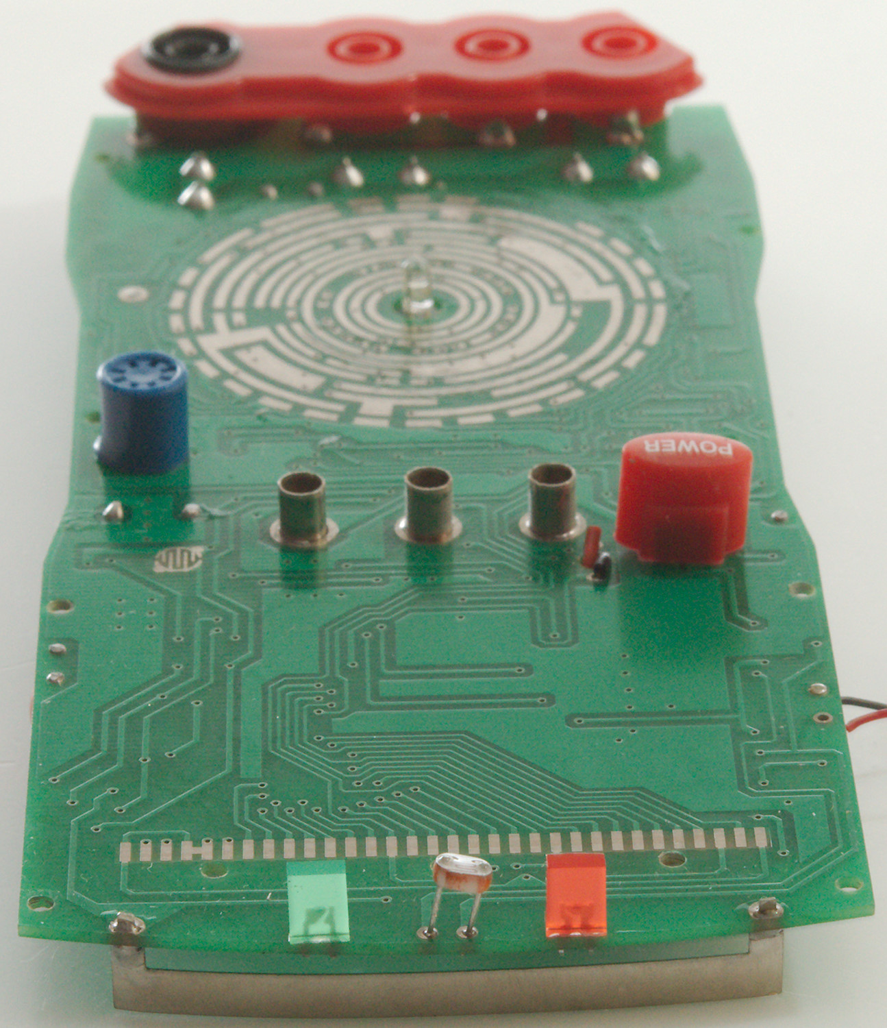
This side of the circuit board has the power switch and transistor tester socket and at the top two leds and a LDR to control the backlight. The sockets for the LC tester is also here.

Conclusion
As usual on cheap(er) DMM's the CAT rating is wrong, meter cannot be rated for 1000V and use 500V fuses. The transistor tester may also be problematic and the LC tester is very problematic.
Looking at the range switch it might look like the meter has a lot of ranges, but it do not. The inductance range is seldom seen on a multimeter and here it is missing some low ranges to check the uH inductors used in modern switchers.
The shutters reduces the risk of mistakes when switching between voltage and current, it is a good safety feature, but the LC inputs are missing them.
To supported as many different measurements as possible the meter has skipped a lot of ranges, this means it is often possible to measure stuff, but with lower resolution.
Notes
How do I review a DMM
More DMM reviews