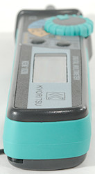
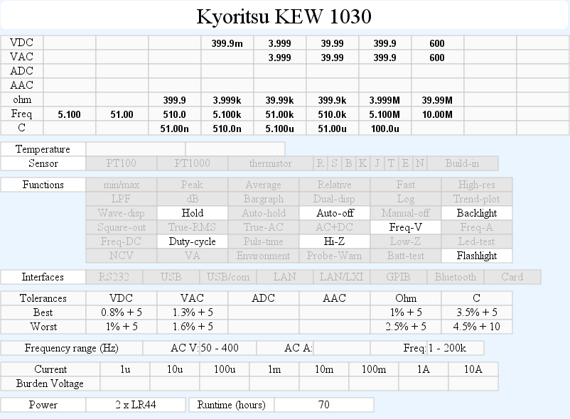
DMM Kyoritsu KEW1030
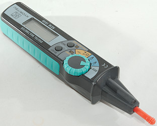
Kyoritsu is a Japanese test equipment manufacturer, this is a small pen multimeter with limited functionality.
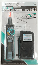
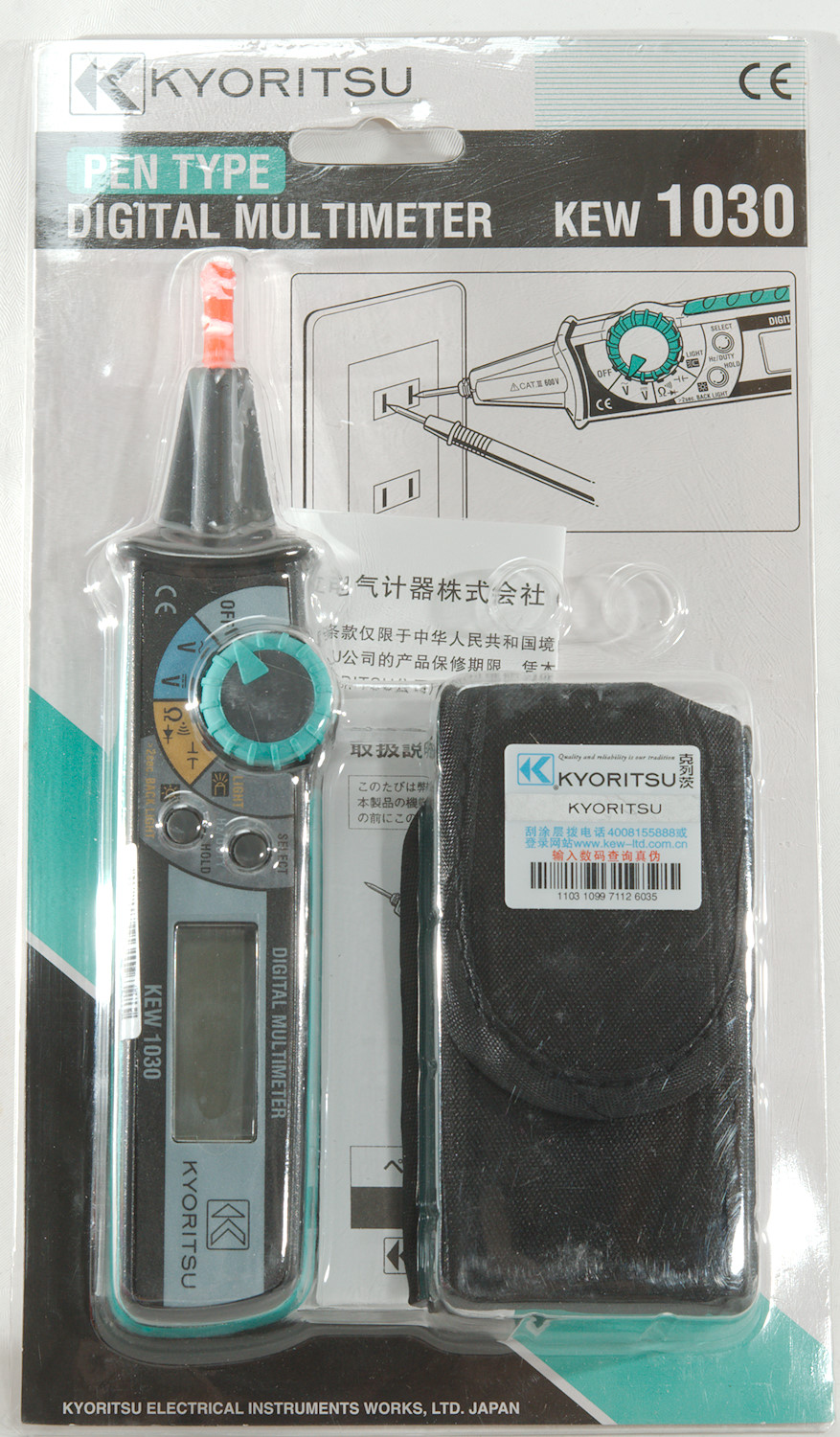
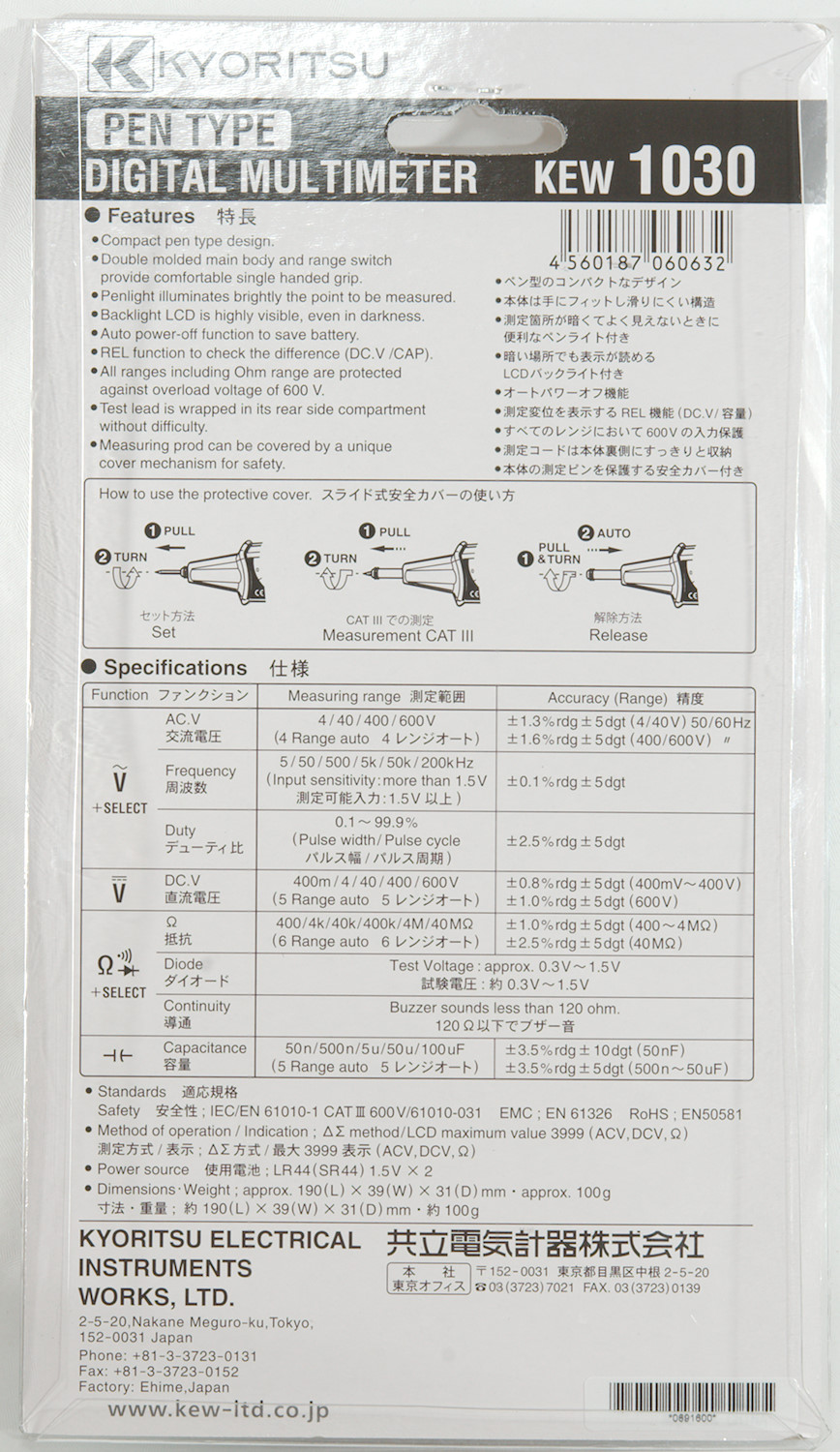
The meter arrived in retail packing.
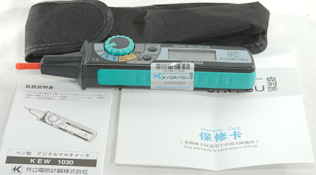
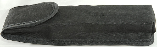
The pack contained the meter, a pouch, a instruction sheet in Japanese and English (It is possible to download it) and a warranty card.
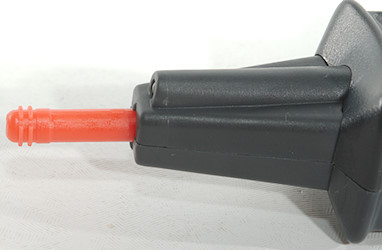
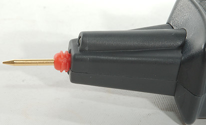
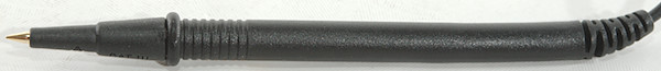
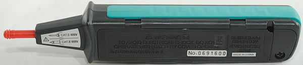
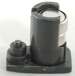
The probe in the meter has a cover that can be placed in 3 different position:
Tip protected, CAT III and CATII (Both 600V)
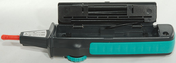
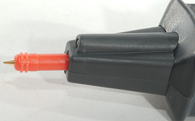
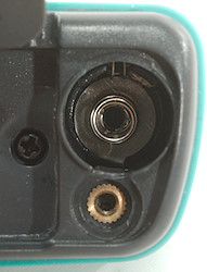
There is no visible black probe, it is hidden inside the meter.
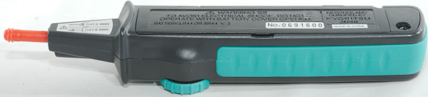
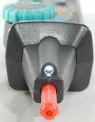
Here the full probe length is out.
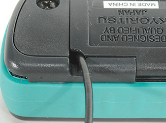
There is a hole in the enclosure for the wire.
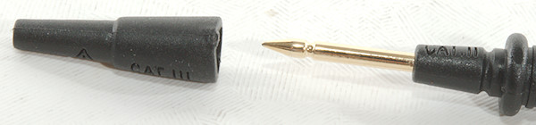
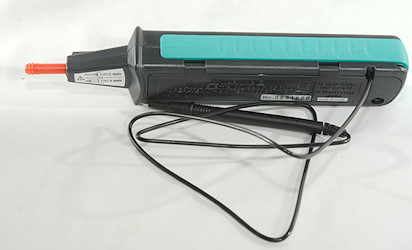
The black probe do also have a removable tip cover and it can be stored inside the meter when the probe is out.
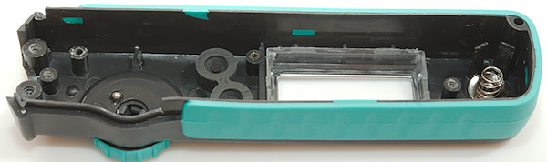
The range switch is a bit stiff, but can be changed with one finger.
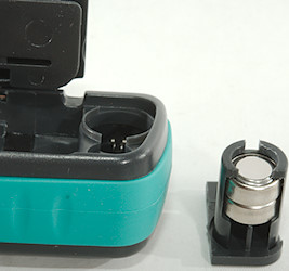
The battery compartment is one screw and it stays in the lid.
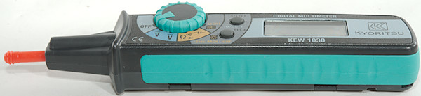
There is a flashlight in the front of the meter.
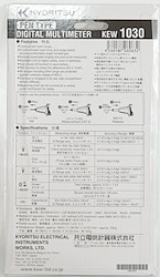
Display
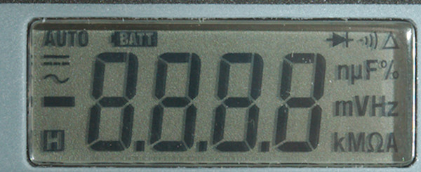
The above picture shows all the segments on the display.
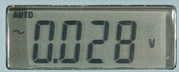
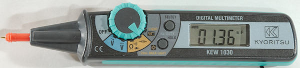
Typical display during usage, it will show the number and what measurement is selected.
Functions
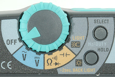
Push buttons:
- Select: This button has a couple of function. In V it will disable autorange and for VAC it will select frequency and duty cycle. In ohm it will change between ohm/diode/continuity. In capacitance it is a REL function.
- Hold: Freezes the display, hold down for background light (Must be pressed shortly again for display to update)
Rotary switch:
- Off: Meter is turned off
- V AC: Voltage AC, frequency and duty cycle.
- V DC: V and mV DC
 : Ohm, diode and continuity
 : capacitance, use SELECT to zero.
- Light: Turn flashlight on, it stays on when going back to other position.
Input
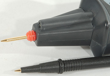
The probes is permanently attached to the meter.
Measurements
- Volt and frequency
- 1 VAC is 5% up at 1.9kHz
- At 1Vrms frequency input range is from 0.6Hz to 10MHz
- Frequency input requires a zero crossing.
- Duty cycle works from 1% to 90% at 100kHz with 1Vpp, precision is within 1.3
- Duty cycle works from 1% to 98% at 100kHz with 2Vpp, precision is within 0.8
- Input impedance is 10..11Mohm on V AC/DC and frequency DC.
- mV DC is high impedance up to about 1.5V, then it drops to 10Mohm
- Over voltage protection is 600VAC/DC
- Current
- Meter do not have current ranges
- Ohm, Continuity, diode and capacitance
- Ohm needs about 3.6s to measure 100ohm
- Ohm is 0.44 open and 0.2mA shorted
- Continuity is quick (About 50ms).
- Continuity beeps when resistance is below 40ohm, but there is some weak noise up to 80ohm
- Continuity is 0.44V open and 0.2mA shorted
- Diode range uses 1.5V, max. display is at 0.999V at 0.2mA, max. current is 0.6mA shorted
- 10uF takes about 3.2 seconds to measure.
- 100uF takes about 17 seconds to measure.
- Over voltage protection is 600VAC/DC
- Miscellaneous
- Current consumption of meter is 0.9mA for DC and ohm, but 1.5mA VAC (Flashlight adds 5mA, backlight adds 3mA, for a maximum of 9.5mA)
- Meter works down about 1.4V where meter turns off, battery symbol shows at 2.4V.
- Reading is stable until meter turns off.
- Backlight starts to fade at 2.4V and is about out at 1.7V
- Flashlight fades slight with voltage until meter turns off.
- The meter needs a few updates to show the correct value
- Viewing angle is good.
- Display updates around 2 times/sec
- Backlight is two red led with bright hot spots, it is possible to read the display in darkness, but it is not a nice backlight.
- Backlight and flashlight will not turn off, except when meter is turned off (Manually or automatic).
- Meter will automatic turn off after 34 minutes
- Weight is 103.5g
- Size is 188.2 x 36.3 x 29.6mm including batteries and with cap on.
- Probes
- Probe wire is soft, thin and 62cm long from the enclosure hole.
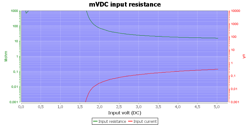
The input resistance at low voltage on DC range.
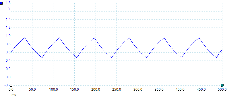
Waveform when measuring 1uF capacitor.
Lowest capacitance range only show correct when REL is used.
High DC voltage can block AC readings.
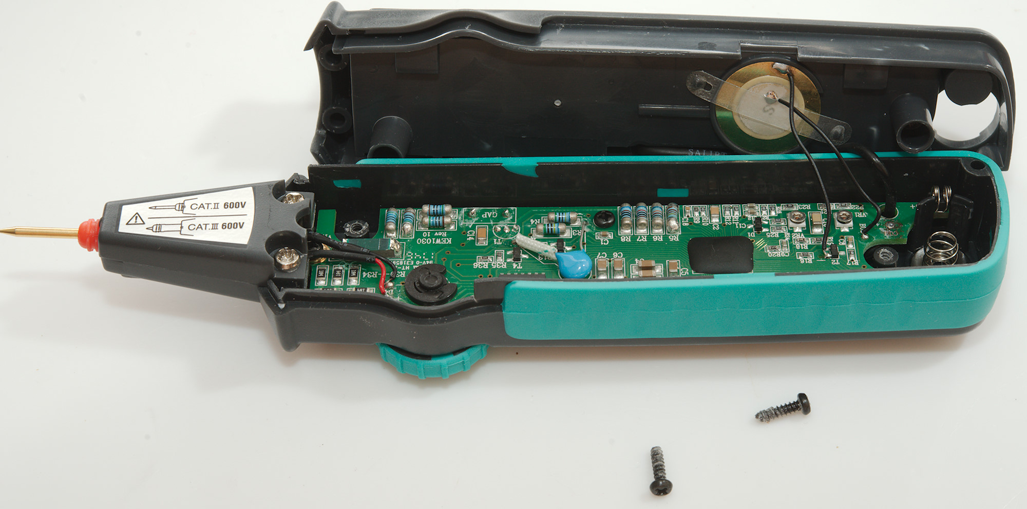
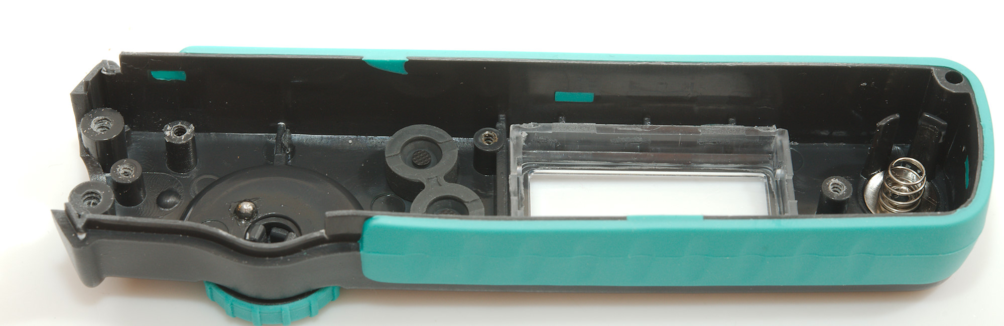
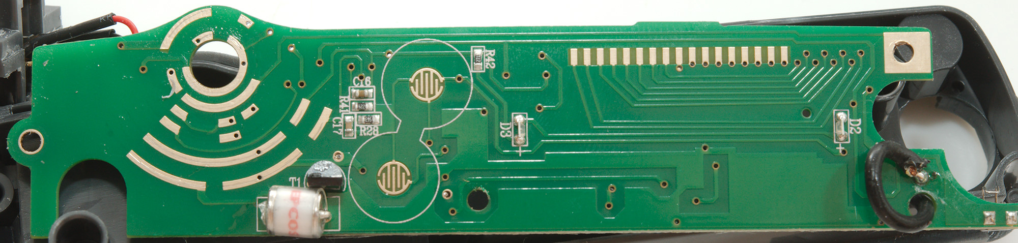
Tear down
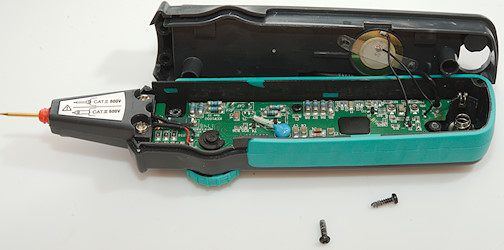
I had to remove two screws to open the meter.
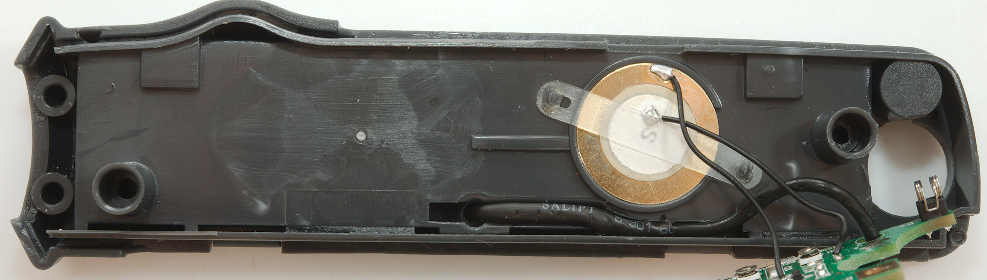
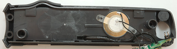
The buzzer is heat staked to the enclosure, this means desoldering the wires if I want to get the circuit board disconnected.
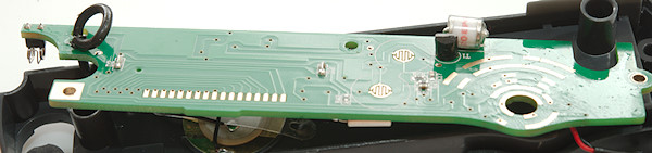
At the front two wires for the led is covered with a layer of heatshrink, they are for the flashlight led.
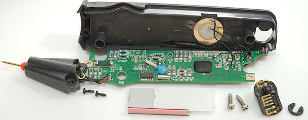
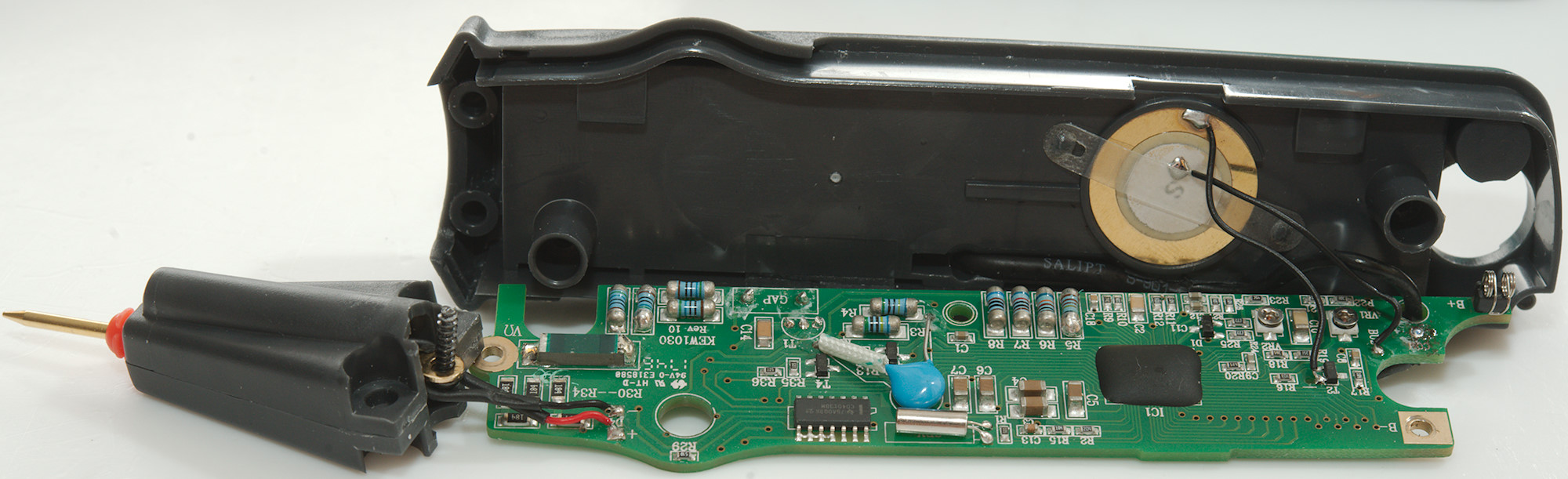
Two screws for the front and 3 for the circuit board, I did also remove the circlip, but that was not necessary.

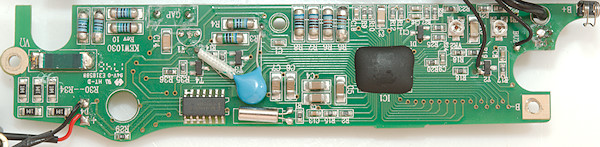
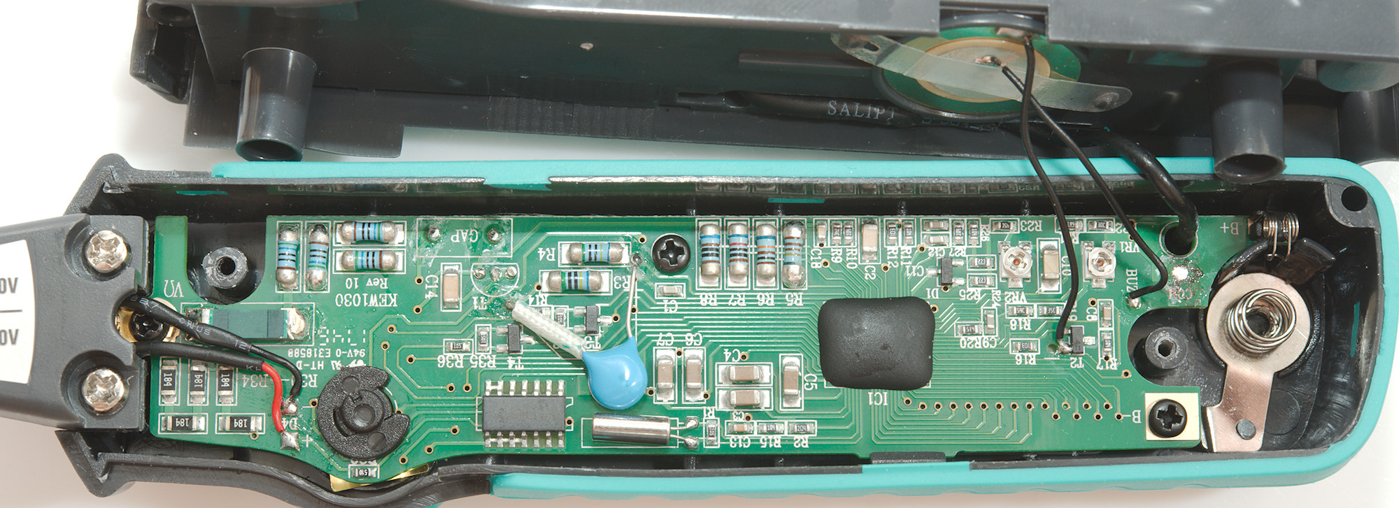
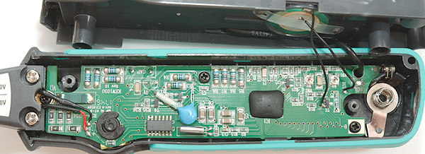
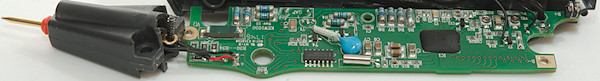
The tip has two paths, one is the 900kOhm for ohm and capacitance input (R30..R34: 5*180kOhm), the other has first a PTC, then 4 resistors (4x560ohm) in parallel and series and then a spark gap. In voltage the signal goes through two resistors (R3 & R4: 2x5Mohm) with a high voltage capacitor in parallel (The blue capacitor), in ohms a transistor (T1) is connected in parallel to the spark gab.
The large capacitors (C3..C7) is used in a boost circuit that is used for the flashlight and more.
The circuit board also has two trimpots.
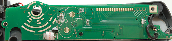
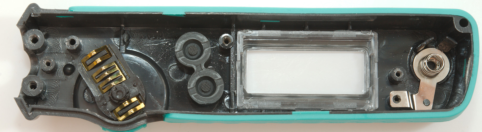
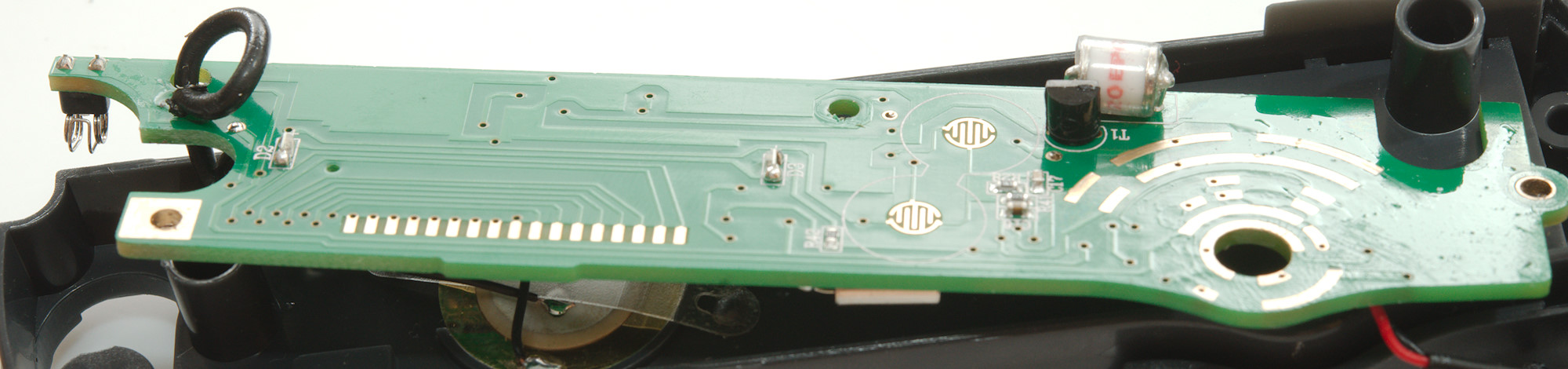
On this side is the pads for the range switch, buttons and LCD, there is also a spark gab and a transistor (T1) and the two leds (D2 & D3) for the backlight.
Conclusion
It is a small and well designed pen meter with protection for the tip and space to store the probe lead, safety do also look good. There is a nice selection of ranges and functions for a pen meter. The user interface is a bit messy to get all the function without too many buttons.
Notes
How do I review a DMM
More DMM reviews