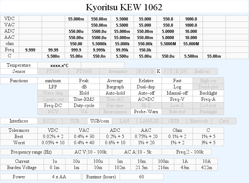
DMM Kyoritsu KEW1062
Kyoritsu is a Japanese test equipment manufacturer, this multimeter is one of their top models.


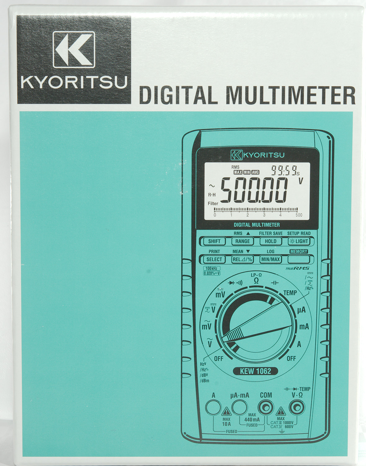
I got it in a cardboard box designed for this model. It only list the meter model, no further information, except the drawing of the meters front.
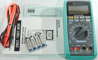
The box contained the meter, batteries, test probes and a manual in Japanese and English. No thermocoupler or pouch.
The manual is very thorough with functions and specifications.
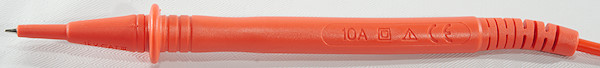
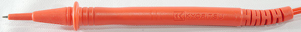

The probes has removable tip covers in soft silicone, the tip and tip cover has the usual CAT markings.
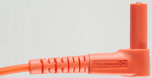
The shrouded plug is a bit on the short size.
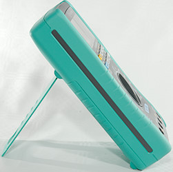
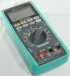
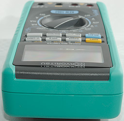
The range switch is fairly easy to turn and with this heavy meter it is stable both lying and standing. The shutters in the ampere range the movement of the range switch can be blocked by inserted plugs.
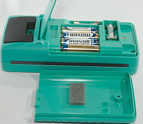
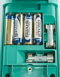
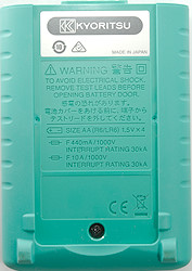
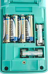
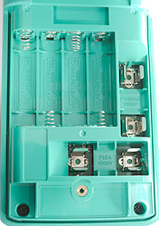
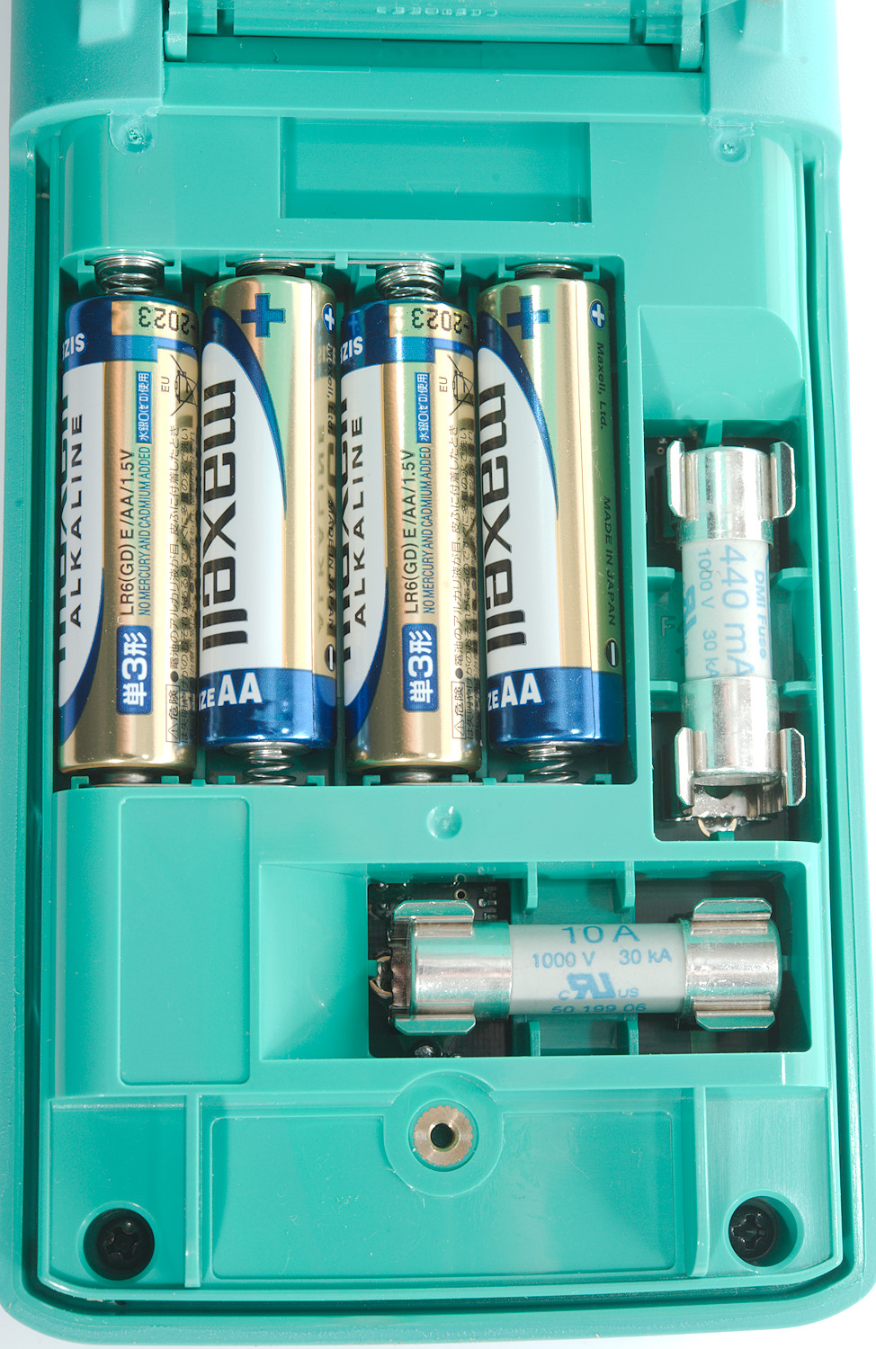
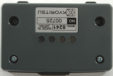
The battery lid lists battery type and fuse ratings, but not size of fuses. There is a good marking for what fuse goes where.
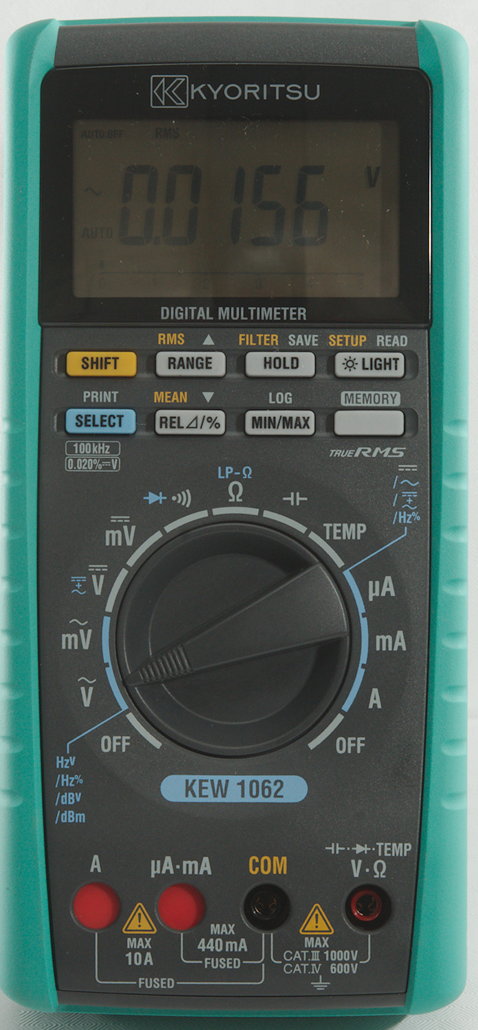
Display
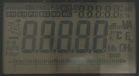
The above picture shows all the segments on the display. The contrast it not very good. The backlight will help in dark surroundings, but not with shadows from a bright lamp.
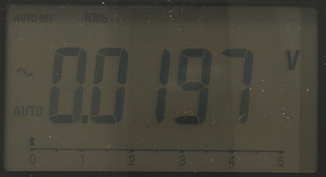
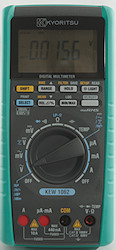
Typical display during usage, it will show the number, bargraph and what measurement is selected.
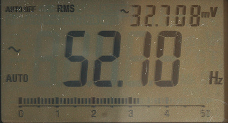
When frequency is selected in AC ranges the voltage moves to the secondary display
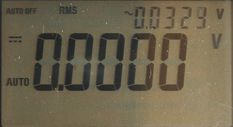
In DC volt a combined AC and DC mode can be selected.
Secondary display functions (After / is small display):
- AC Volt and mV: VAC, frequency/VAC, frequency/duty cycle, dBV/VAC, dBm/impedance
- DC Volt: VDC, DC+AC, VDC/VAC
- Current: ADC, AAC, AC+DC, DC/AC, frequency/duty cycle
- REL: V/ref, percent/ref, A/ref, percent/ref, ohm/ref, percent/ref, capacity/ref, percent/ref
- Capacity: value/range
- min/max: value/Time
- Memory: Memory number or depending on configuration time.
Functions
The buttons has to be pressed down with a bit of force or they will not make contact.
Buttons:
- Shift (Yellow): Select the yellow functions on the buttons.
- Range: Press to select manual ranging, press again to change range, hold down for automatic ranging. In dbM it will select impedance.
- Hold: Freeze display, press twice to activate auto-hold and 3 times to select peak detect mode.
- Light: Press to turn backlight on, hold down to turn backlight off.
- Select (Blue): Select blue modes on rotary dial.
- REL/%: Remember current value and show new values relative to this, either as a value or as percent.
- Min/max: Select between max/min/avg, max, min, avg. The max/min/avg shows current value. Hold down to disable.
- Memory: Activate memory functions, see below.
Buttons when shift has been pressed:
- RMS: Select RMS mode for AC measurement
- Filter: Enable a low pass filter for AC measurement.
- Setup: Configuration of meter, this is clock, default dBm impedance, default RMS/mean, default logging interval, sound on/off.
- Mean: Use mean for AC measurements.
Buttons when memory has been pressed:
- Memory: Hold down to leave memory mode.
- Save: Select single point save. Next pressed on save will each save a single measurement (Space for 100). Hold down the key to delete data.
- Read: Read saved data, press Save or Log to select memory to view, use arrows to move in data.
- Log: Select logging interval with arrows, then start logging on the second press (Only one session can be recorded with up to 10000 records). Hold down the key to delete data.

 : Used for adjusting logging interval and selecting memory no.
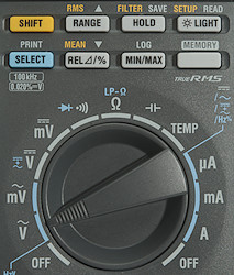
Rotary switch:
- Off: Meter is turned off
- VAC: Show AC voltage and frequency, use the blue button to select frequency, dBm or dBV.
- mVAC: Show AC millivoltage and frequency, use SELECT for frequency, dBm or dBV.
- VDC: Show DC voltage, use SELECT for AC+DC or AC,DC
- mVDC: Show DC millivoltage.
 : Continuity and diode.
 : Resistance, use SELECT for low power resistance.
 : capacitance.
- Temp: Temperature
- uA: Micro ampere current DC, AC, AC+DC, AC,DC and frequency can be selected with SELECT.
- mA: Milli ampere current DC, AC, AC+DC, AC,DC and frequency can be selected with SELECT.
- A: Ampere current DC, AC, AC+DC, AC,DC and frequency can be selected with SELECT.
- Off: Meter is turned off
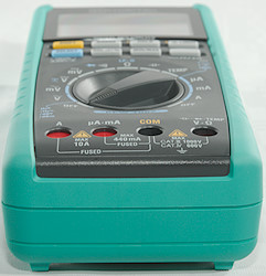
Input
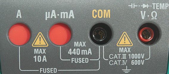
- 10A: High current.
- mAuA: The lower current ranges, the selector switch will change between two different shunts.
- CON: The common terminal for all ranges.
- xxx: All other ranges.
Measurements
- Volt and frequency
- At 10mVrms mVAC frequency input range is from 1.4Hz to 60kHz
- At 100mVrms mVAC frequency input range can be stretched to 75kHz.
- At 1Vrms VAC frequency input range works from 1.4Hz to 70kHz
- At 2Vrms VAC frequency input range works from 1.4Hz to 150kHz
- Frequency input do not requires a zero crossing.
- Duty cycle in mVAC works from 13% to 8% at 1kHz with 1Vpp, precision is within 1.0.
- Max/min needs about 110ms to capture a voltage on DC.
- Peak needs about 0.15ms to capture a positive DC voltage.
- 1 VAC is 5% down at 220kHz, AC+DC is similar(RMS will not work at the frequency).
- 1 VAC is 5% down at 100Hz when filter is activated (RMS will not work at the frequency).
- dBm reference impedance can be select from: 4, 8, 16, 32, 50, 75, 91, 110, 125, 135, 150, 200, 250, 300, 400, 600, 800, 900, 1000, 1200. Default is 600.
- Input impedance is 10..11Mohm on DC, AC and mVAC. AC and mVAC is capacitive coupled.
- mV DC range about 110Mohm up to around 4V, then it will drop to about 1Mohm at 8V and continue to drop slowly
- Over voltage protection is 1000VAC/DC
- Current
- A range has audible alarm above 10.5A
- uA & mA current is protected by a 0.44A/1000V 10.3x35mm (38mm fits) fuse, this means any current above 400mA can blow the fuse.
- 10A current is protected by a 10A/1000V 10.3x38mm fuse.
- Ohm, Continuity, diode and capacitance
- Ohm needs about 3.4s to measure 100ohm, low resolution mode do not improve speed.
- Low power ohm needs about 2.2s to measure 100ohm (It uses a higher range).
- Ohm is 2.2V open and 0.81mA shorted
- Low power ohm is 0.56V open and 0.005mA shorted
- Continuity is very fast (Below 10ms, but not latched).
- Continuity beeps when resistance is below 100ohm.
- Continuity is 3.5V open and 0.44mA shorted
- Diode range uses 3.5V, max. display is 2.4V at 0.19mA, max. current is 0.43mA shorted
- 10uF takes about 5.3 seconds to measure.
- 11000uF takes about 12 seconds to measure.
- Over voltage protection is 1000VAC/DC
- Miscellaneous
- Current consumption of meter is 41mA in AC and 16mA in DC, other ranges is around 16mA (With backlight in AC total is 46mA).
- Meter works down to 2.0V where it turns display off, battery symbol shows at 4.2V.
- Reading do not change with battery voltage.
- Backlight is stable until about 2.2V.
- When meter is turned off it uses about 0.3mA from the batteries.
- It is possible to switch between RMS and mean in AC readings, default is RMS, but can be changed in configuration.
- Meter can be started in averaging mode, where it will average 8 readings (Hold down min/max while powering on).
- Logging interval: 1s, 2s, 5s, 10s, 30s, 1m, 10m, 30m
- The meter will often show the correct value in first display update, but do also sometimes slowly change to a value.
- Viewing angle is good, but contrast is fairly low.
- Display updates around 6 times/sec
- Bargraph updates 15 times/sec.
- Backlight will automatic turn off in about 60 seconds.
- Meter will automatic turn off in 20 minutes, this can be disabled.
- Standard probes cannot be seated completely.
- Weight is 572g without accessories, but with batteries.
- Size is 192 x 90 x 48mm.
- Probes
- Probe resistance 29mOhm for one.
- Probe wire is fairly soft and 89cm long.
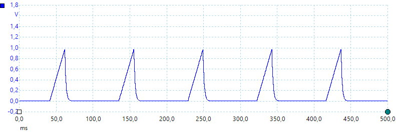
A look at the capacitance measurement waveform.
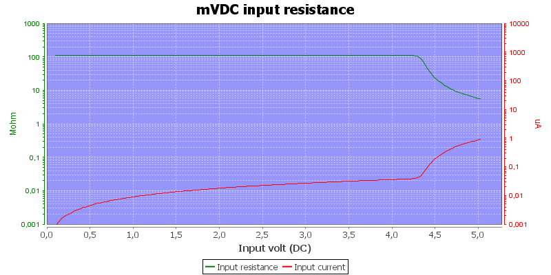
The input resistance in mVDC
There is a 2.4V range in mV with 110Mohm input impedance.
High AC voltage can block for DC readings.
Software
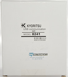
The computer interface and software is not included with the meter, but must be bought separately and is not cheap.
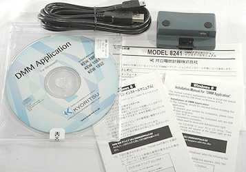
What you get is a USB interface to mount in the meter, a USB cable, software and manuals in Japanese and English.
The manual includes a description of the protocol used (It is very simple).
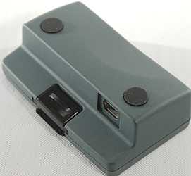
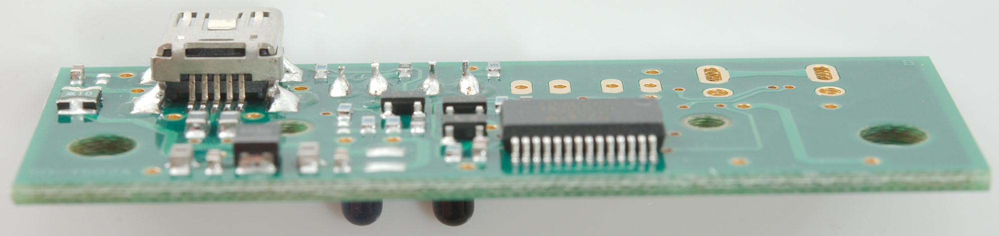
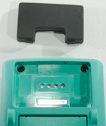
The interface is a small box with a mini USB interface and optical communication to the meter.
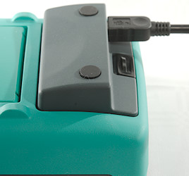
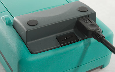
Here it is clipped into the meter and the USB cable connected.
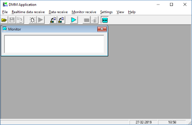
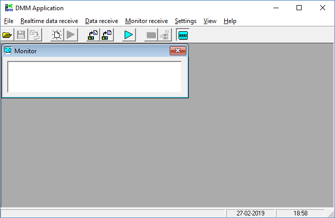
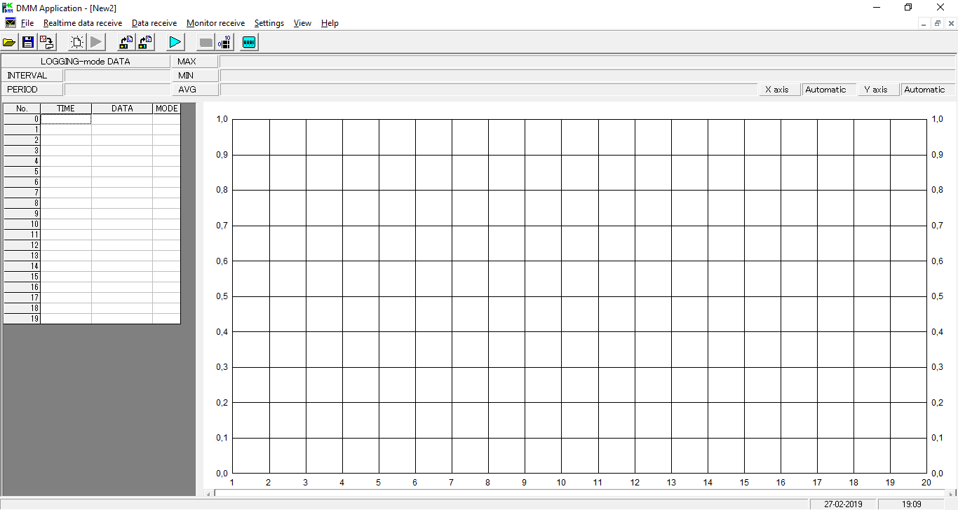
Starting the software it looks like this, the window is not in a fixed resolution, but can be made larger or smaller.
The about box.
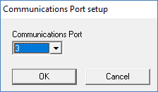
Before connecting to the meter I had to select a COM port.

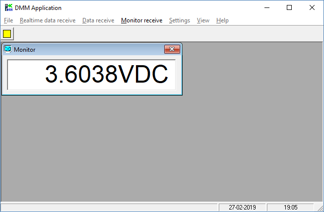
Pressing the start button and I get reading from the multimeter, while this is running my only option is to stop it.
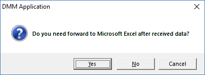
I can also select a more advanced view, this always get me a question about forwarding data to Excel. This is not possible on my test computer because I do not have Excel installed.
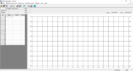
The more advanced view looks like this and it has 3 applications.
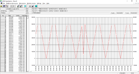
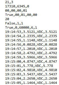
Download logging data from the meter and show it.
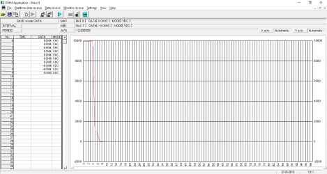
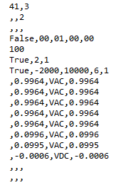
Download saved data from the meter and show it, the curve it not much use here.
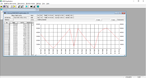
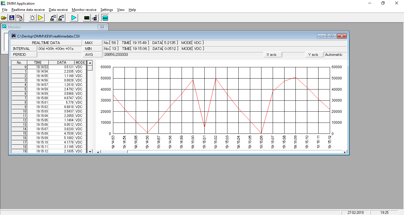
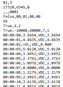
Real time record data from the meter.
One detail I noticed with the graph, it shows a number without any decimal point, this means a range change can look like the value at 19:15:01. It was above 55000, this means the meter change range and then the value was only 5778 and that is the location it was plotted in the curve (Not very good).
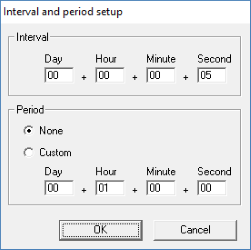
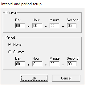
The real time recording can be configured with sample rate and time period.
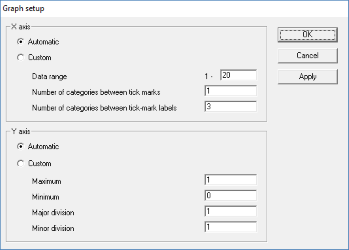
The chart can also be configured a bit.
The table with data can be saved in csv format. Save mode data do not include time, logging mode data include offset time and real time data include time. The clock in the meter is not used to time stamp the data.
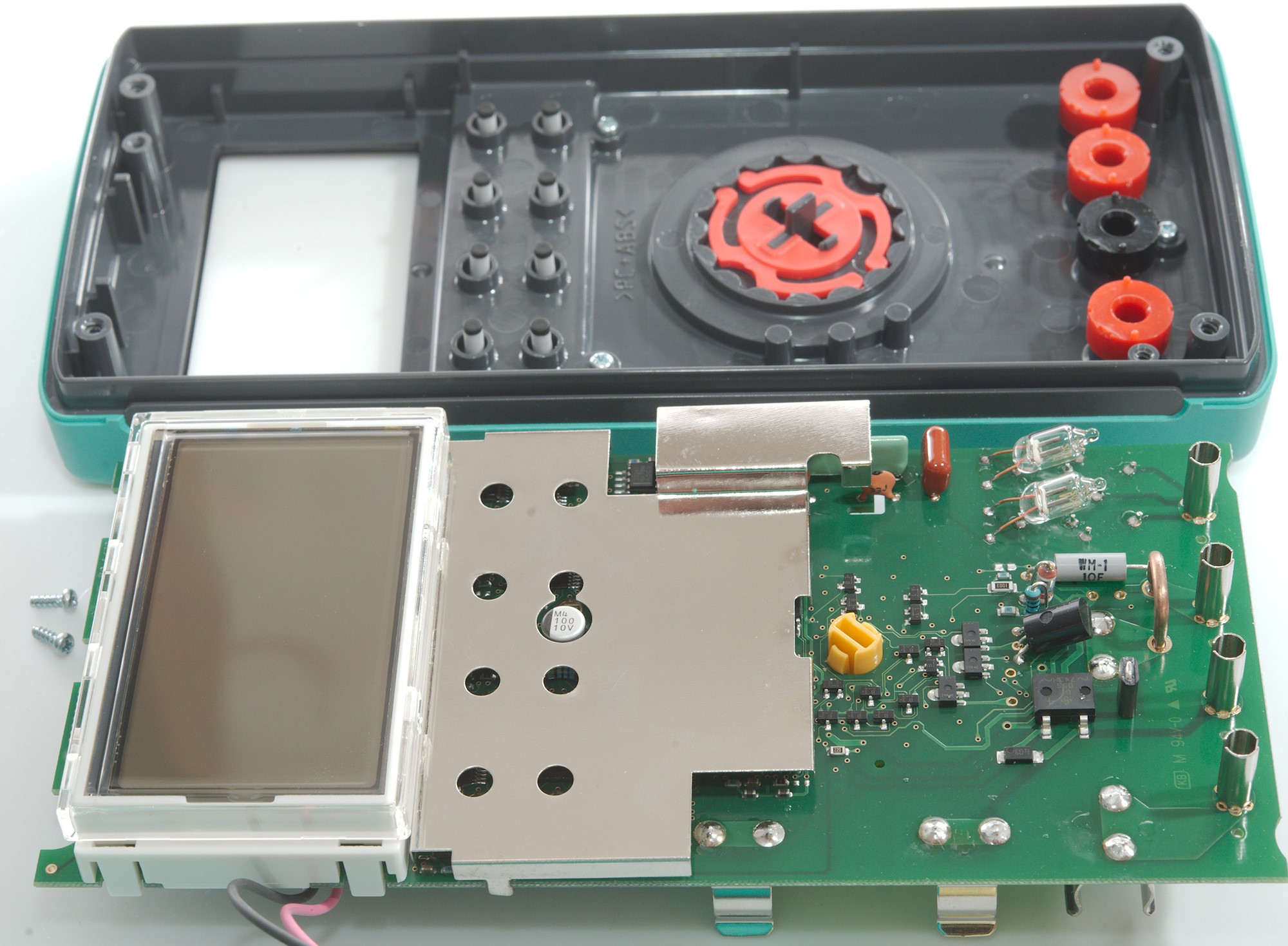
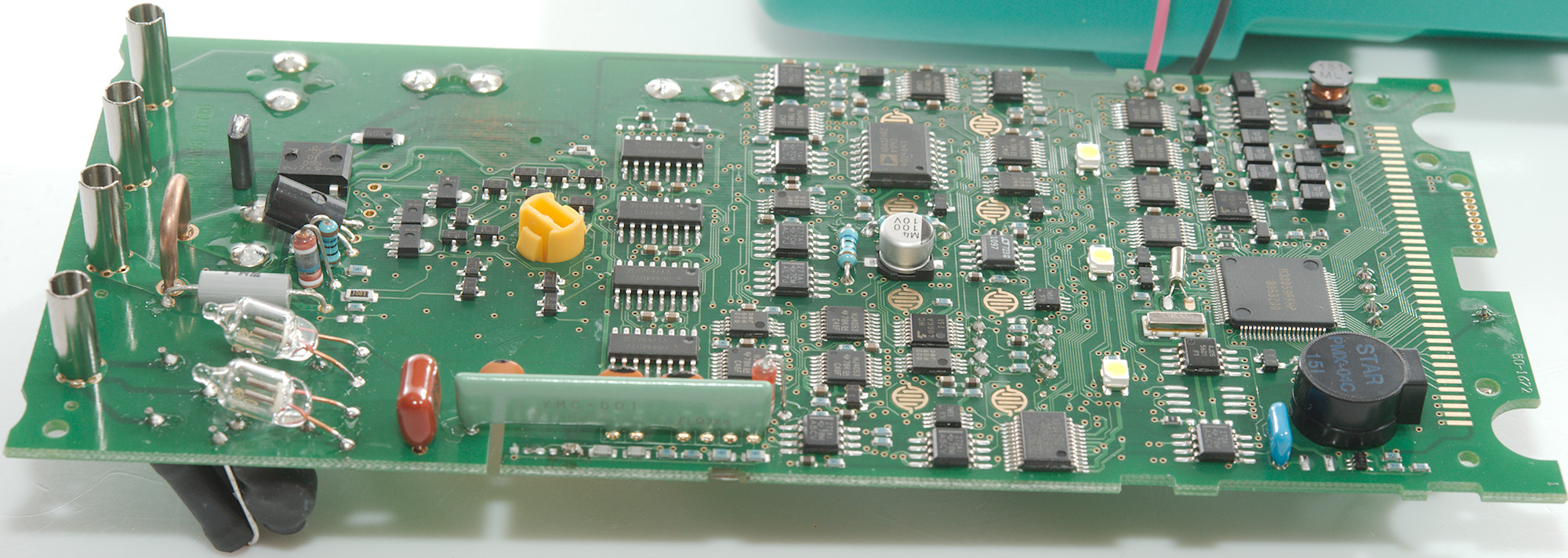
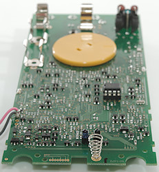
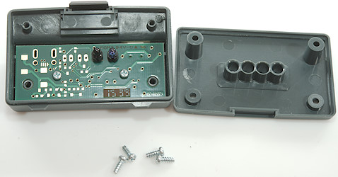
Tear down

I had to remove four screws and two fuses to open the meter.
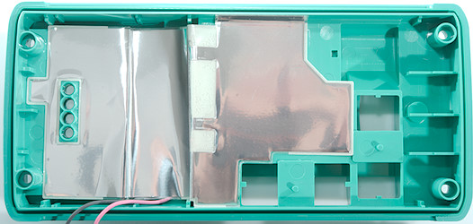
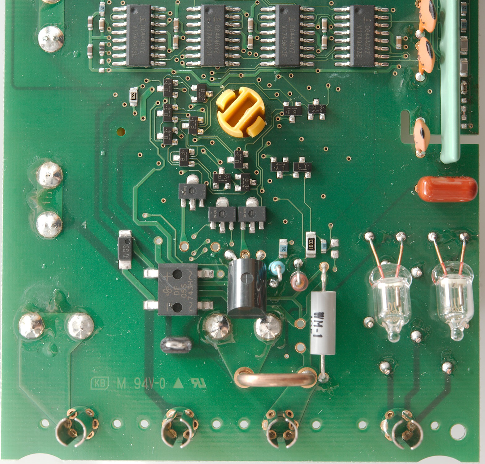
This meter has lots of shielding, probably because it can measure very low voltage levels.
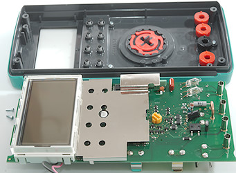
Getting the circuit board out was only two more screws.
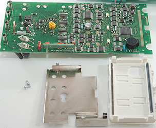
The shield had to be desoldered and the display was two screws.
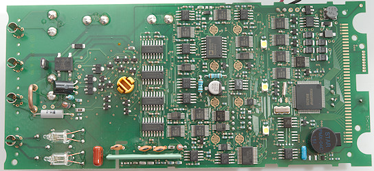
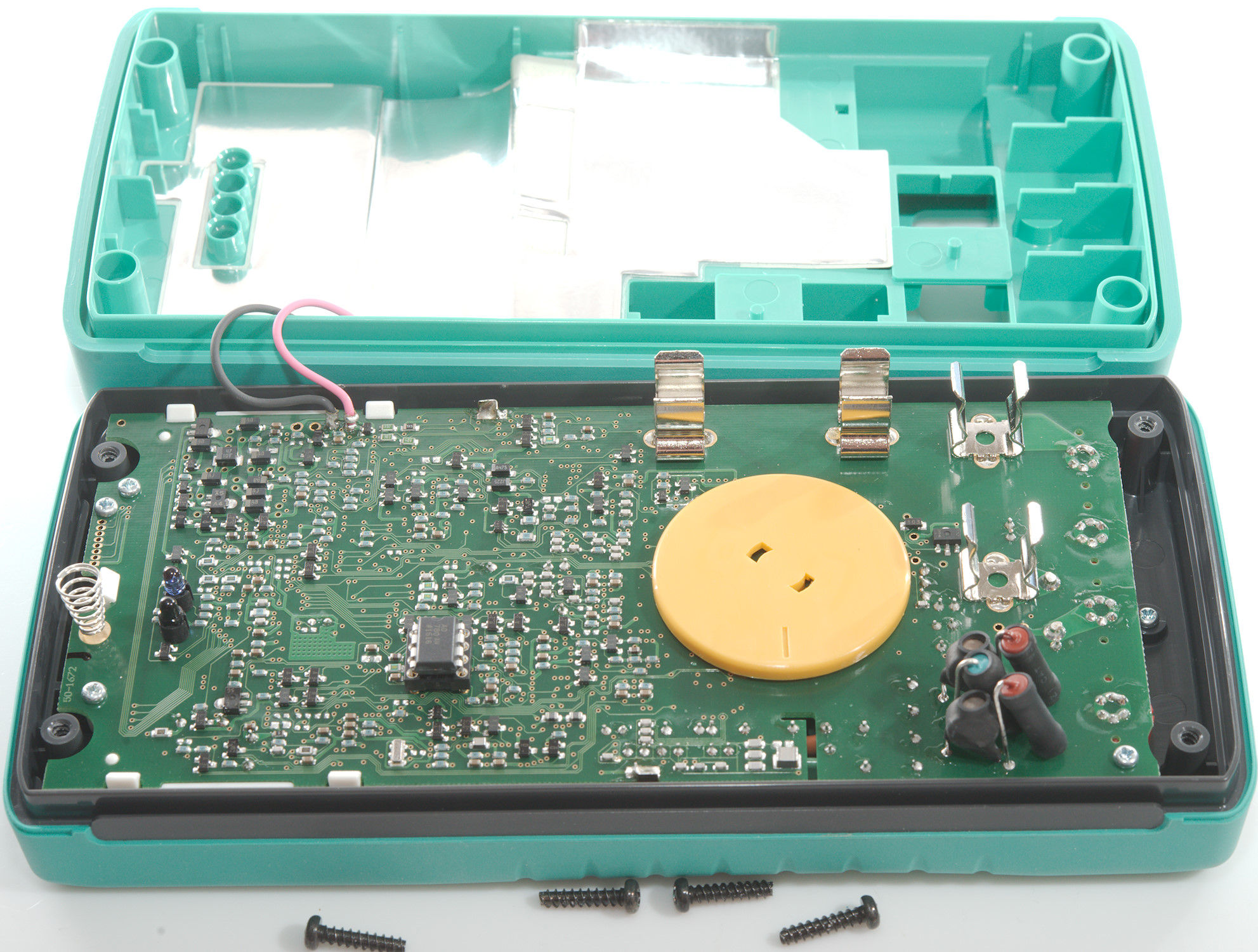
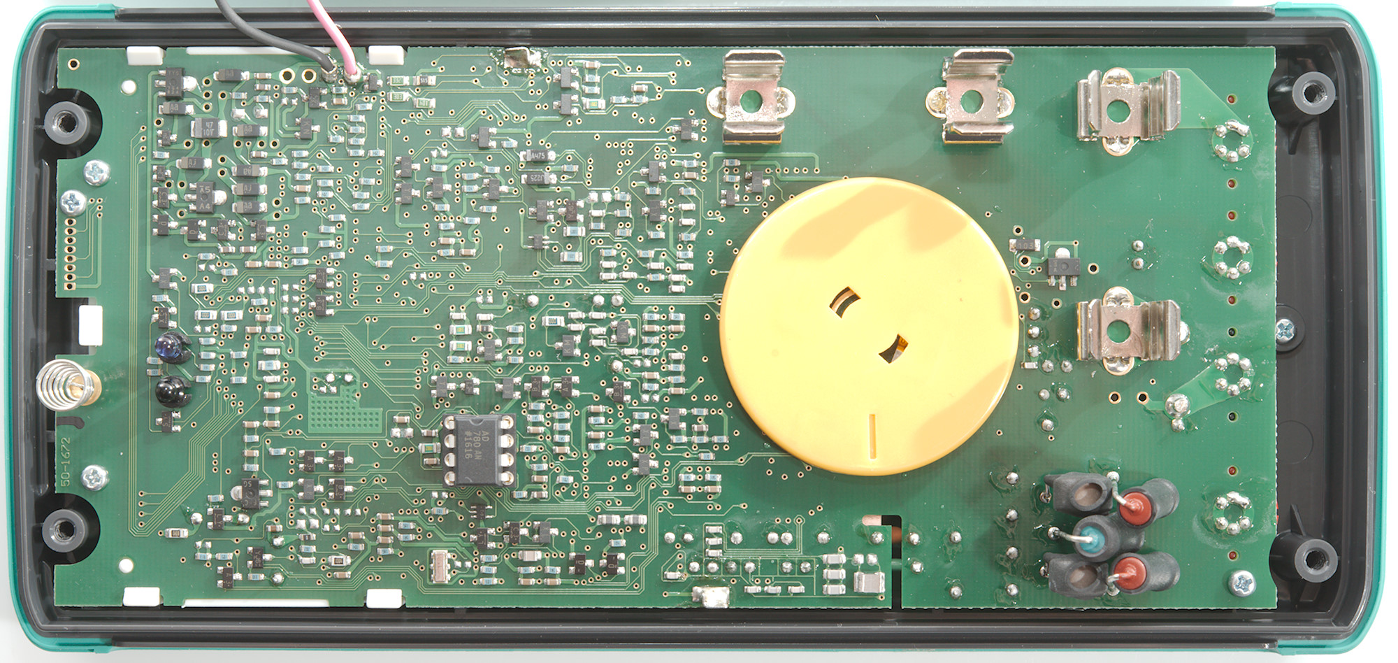
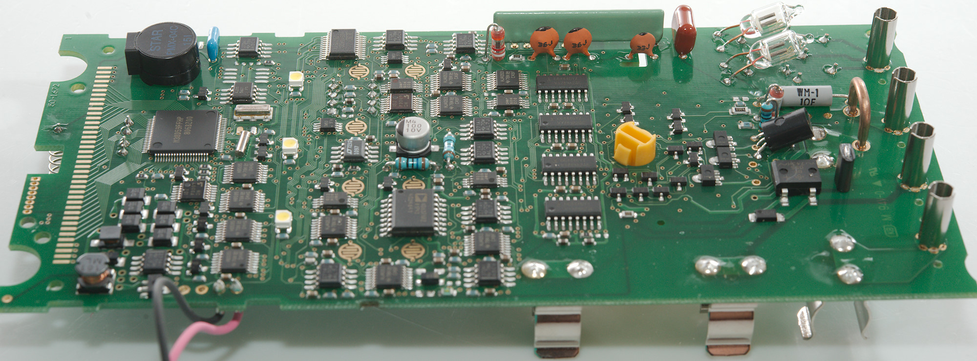
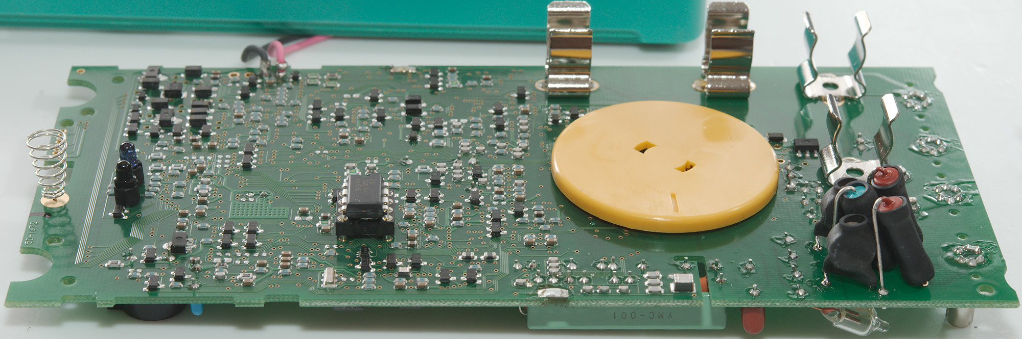
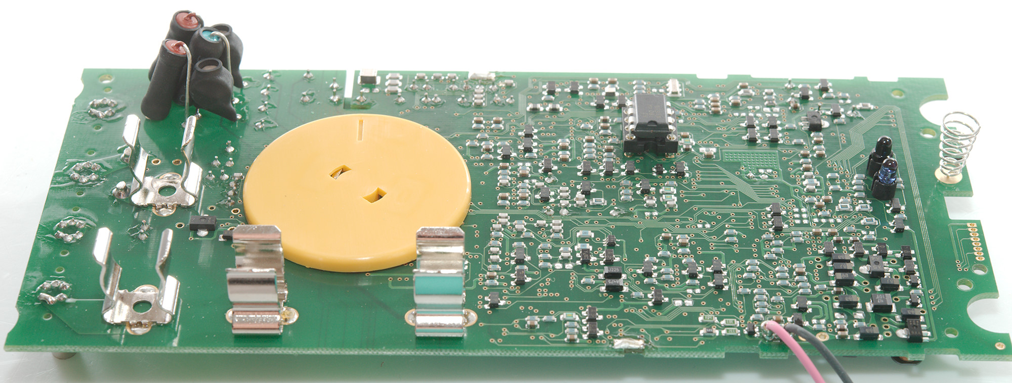
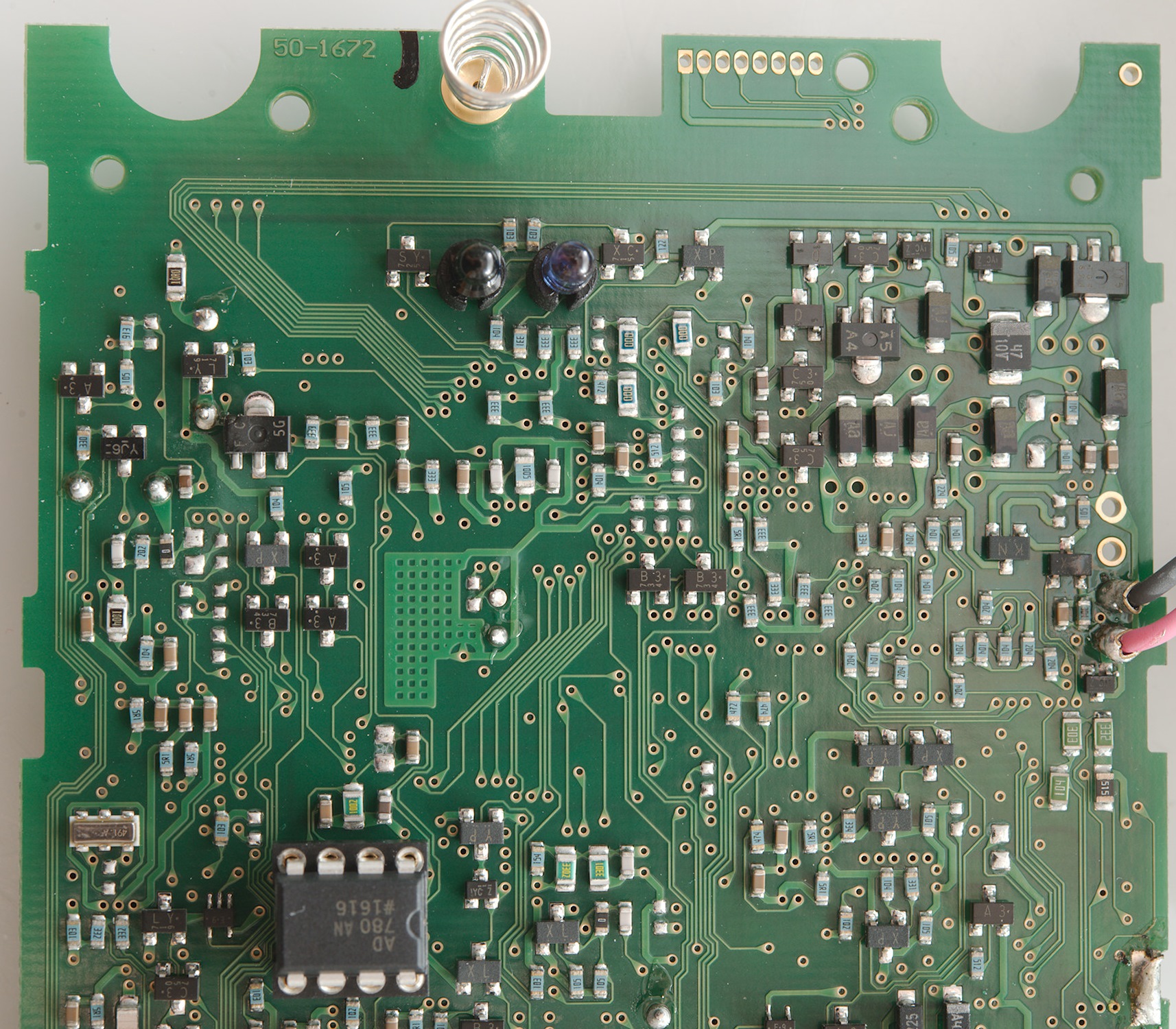
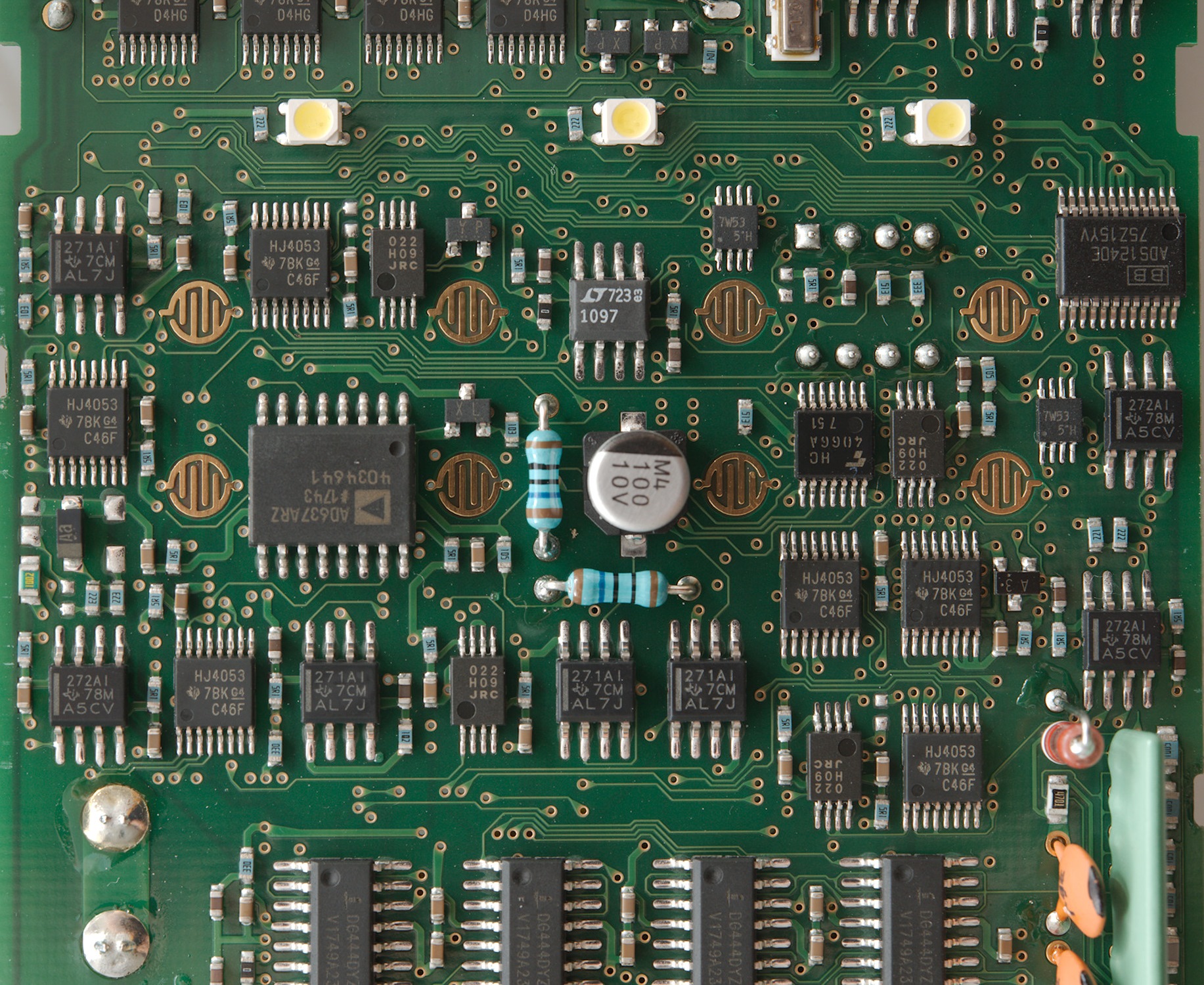
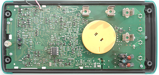
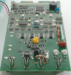
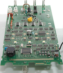
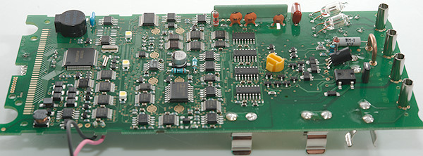
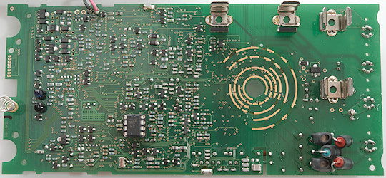
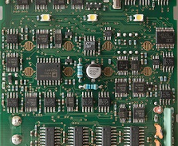
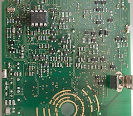
Most electronic is on this side.
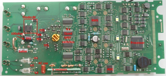
The current is made the usual way with a 1ohm mA shunt and 100ohm uA shunt and a diode bridge with one extra diode across for protection.
The voltage and other input has 3 paths (Marked V1, V2 and V3 on above photo). The V1 and V3 is protected by a PTC, series resistor and spark gab, the V2 is 468kOhm resistor.
There is a transistor pair marked TP1 with a 100kOhm resistor before it. The other TP are also used for protection, but single sided for ohms and similar ranges. TP4 is in series with a similar transistor on the other side.
In temperature the V2 path is used with the transistor pair TP1 for protection.
In capacity V1 is used with transistor TP5 and through 100kOhm with TP1. V3 is used with transistor TP4.
In ohm input the V2 path is used with the transistor pair TP1 and V3 with transistor TP2 for output.
In continuity input the V2 path is used with the transistor pair TP1 and V3 with transistor TP3 for output.
In mVDC the V2 path is used with the transistor pair TP1
In VDC the V1 path is used with the V resistors.
In VAC and mVAC the V1 path is used with the AC cap and V resistors. There is capacitors parallel with the V resistors to get better frequency response.
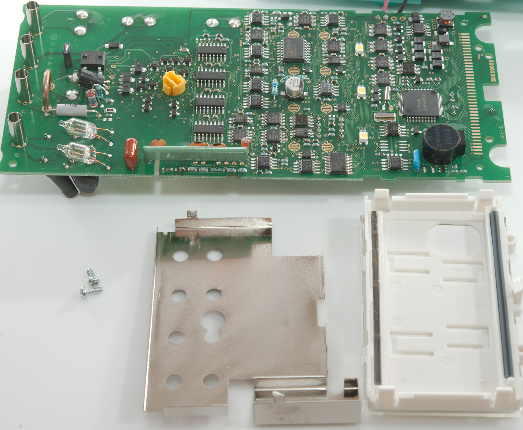
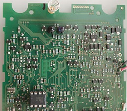
Processor: M38D59FFHP: 60kB flash, 2kB ram, 8 bit cpu.
ADC: ADS1240 24 bit
RMS converter: AD637
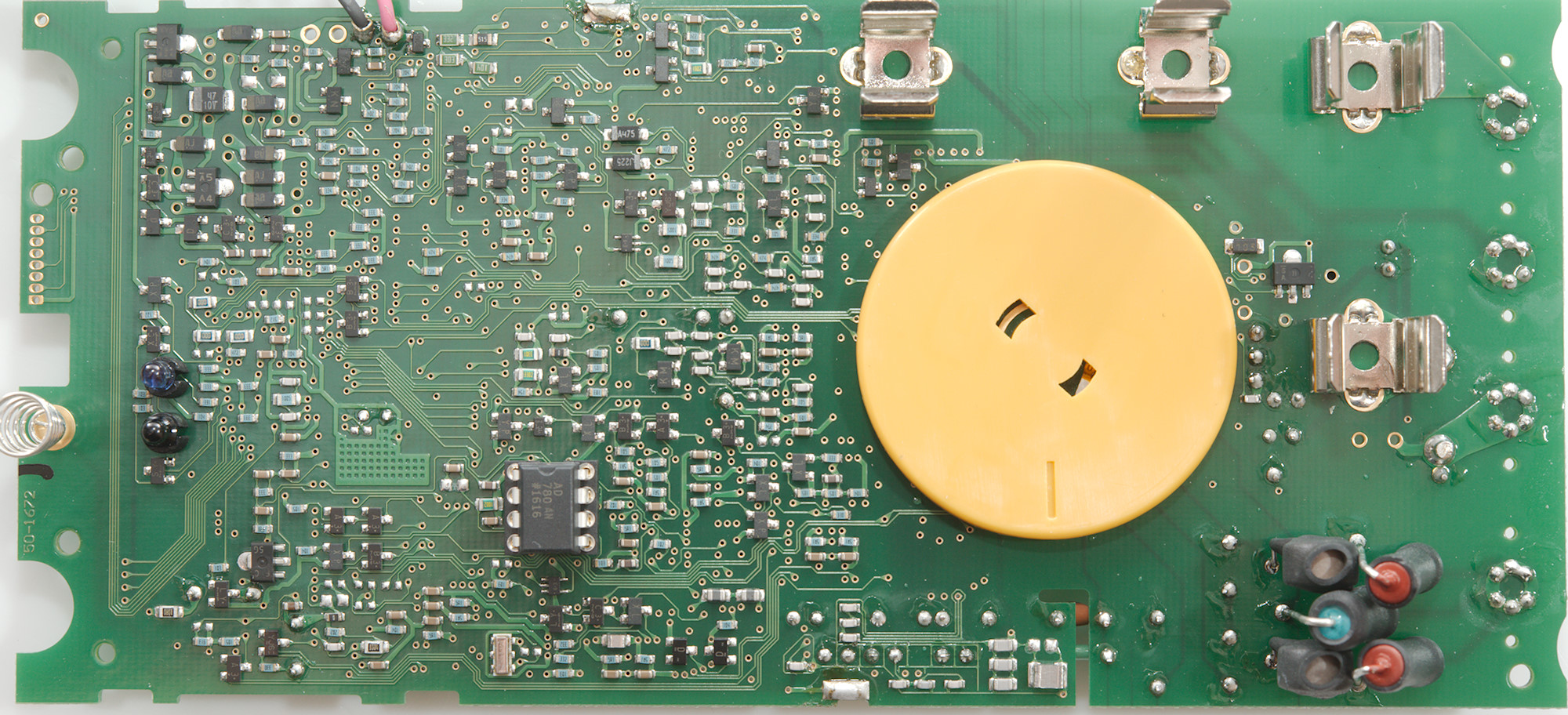
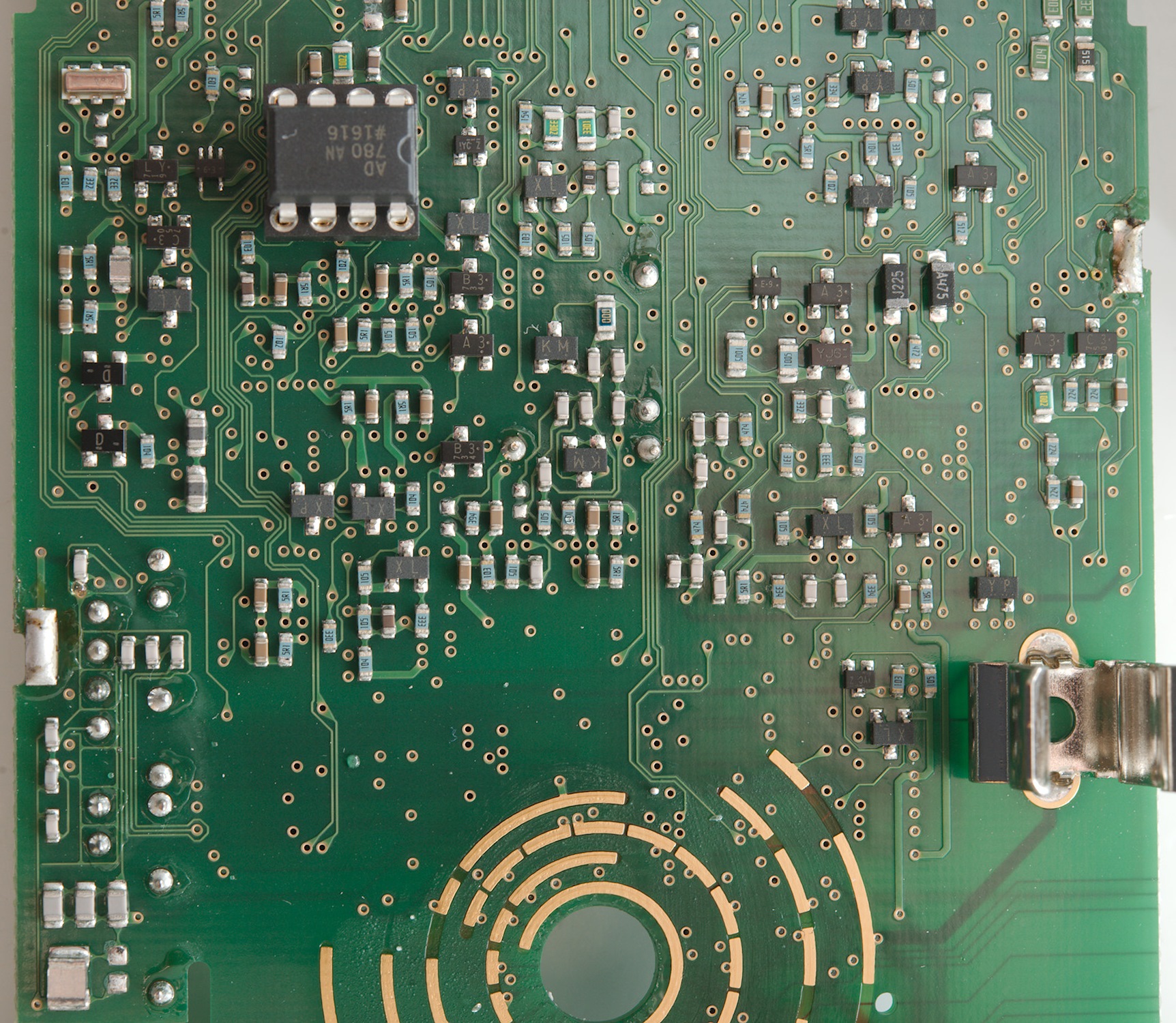
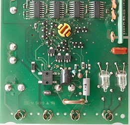
Reference: AD780: 2.5V 20ppm/1000h it is on the other side in a socket.
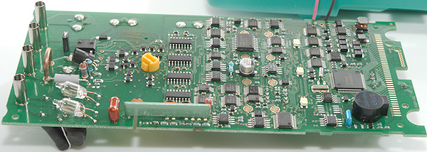
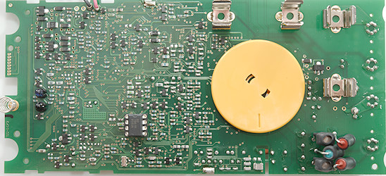
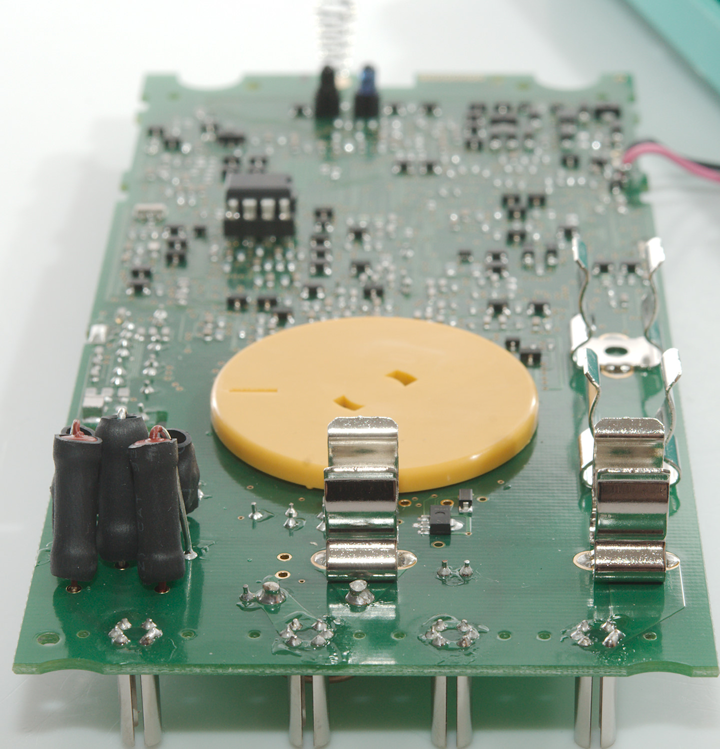
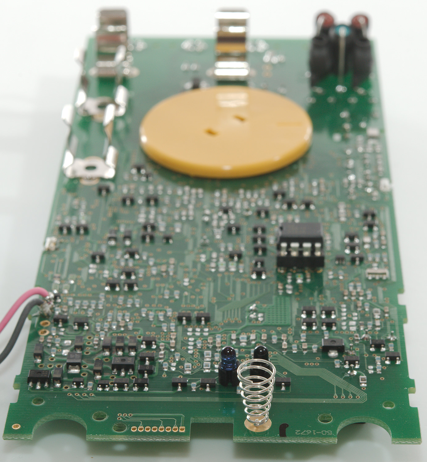
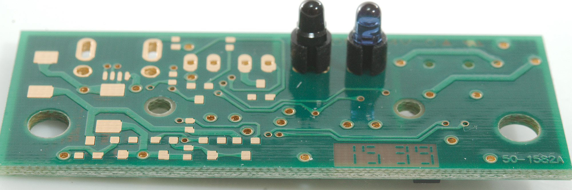
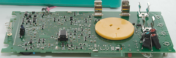
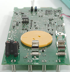
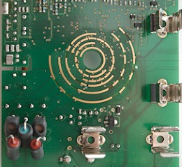
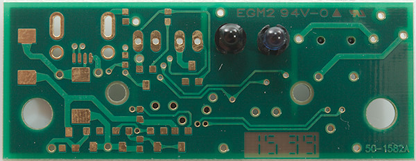
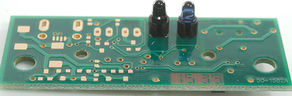
On this side is a lot of transistors/diodes, resistors and capacitors, together with the reference. The remote interface is two diodes, even though there are four windows in the enclosure. The input PTC's and resistors are also here, nicely packed in heat shrink.
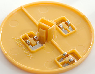
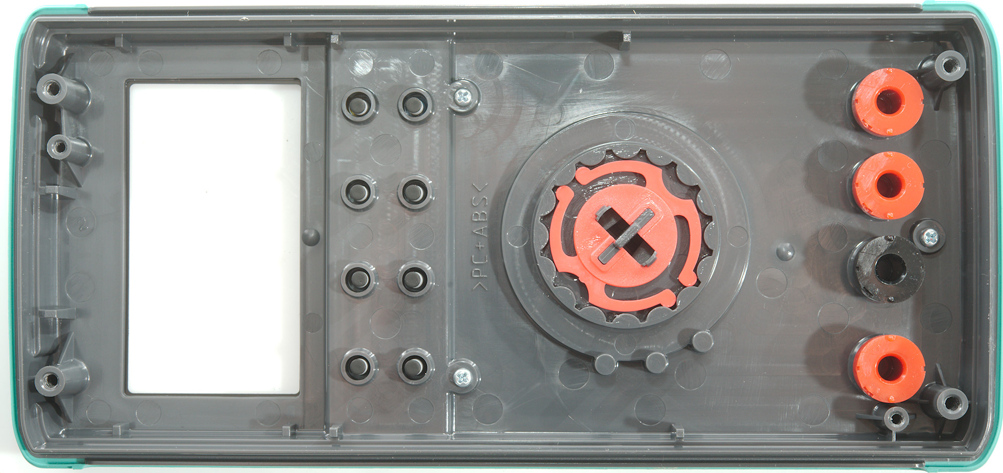
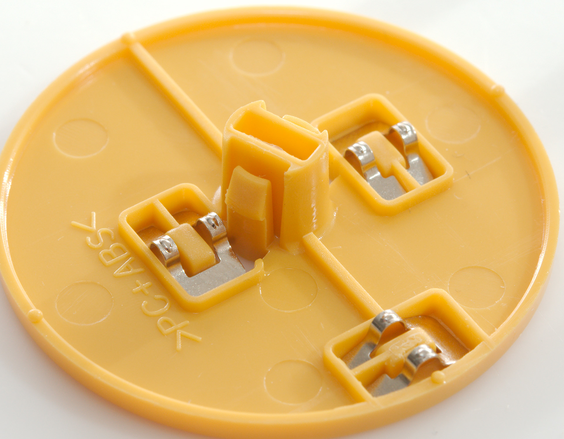
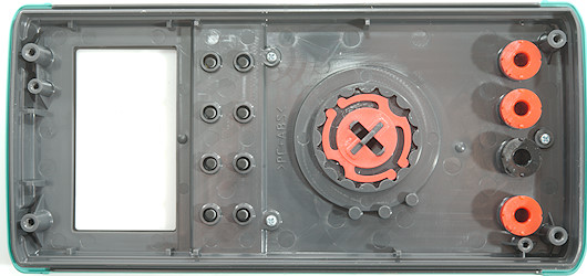
The range switch can easily be removed, but watch out for the small contact sliders, they will fall out!

More high resolution pictures:
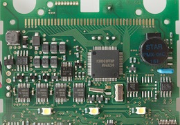
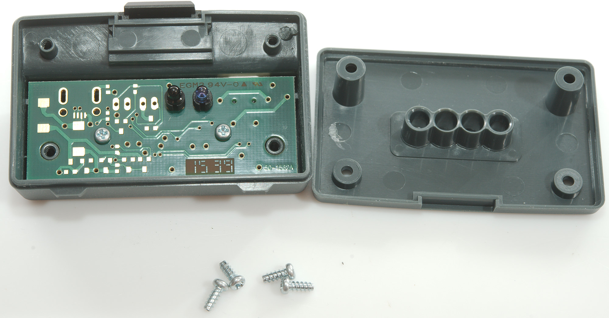
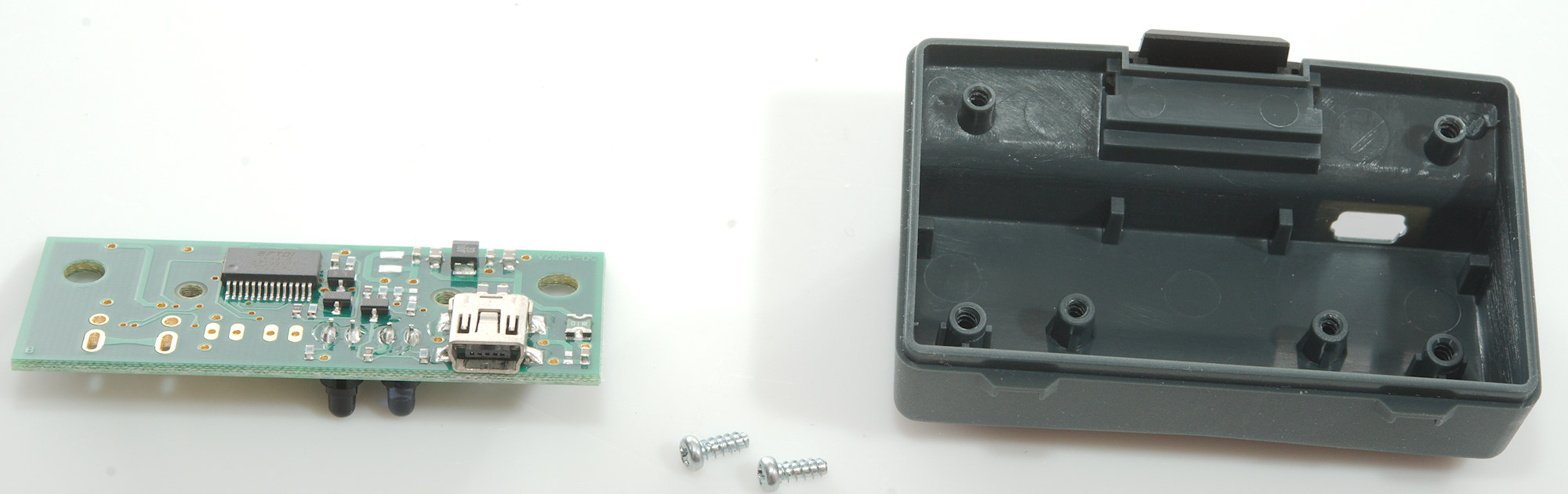
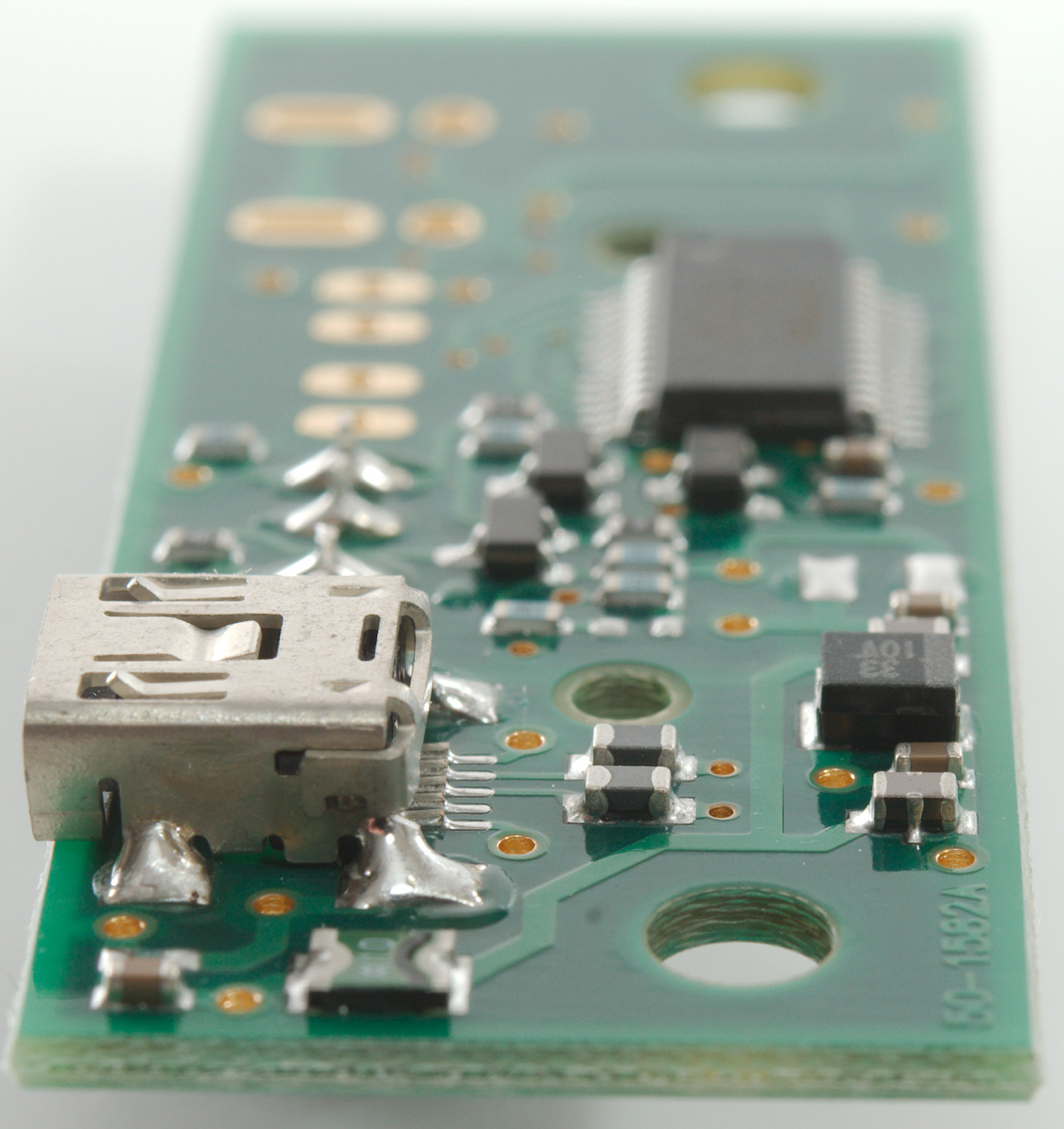
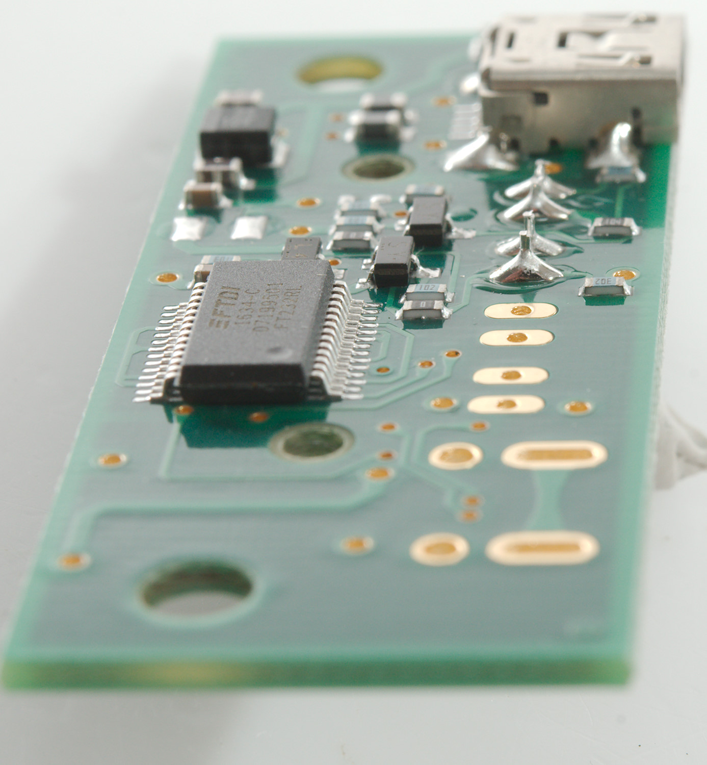
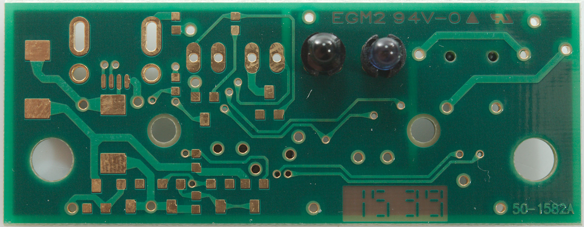
Tear down USB interface
There was four screws to hold it together.
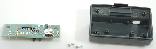
And two more for the circuit board.
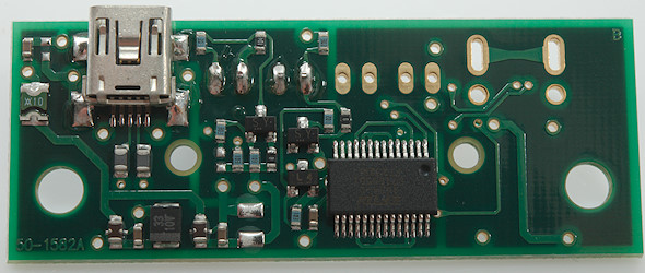
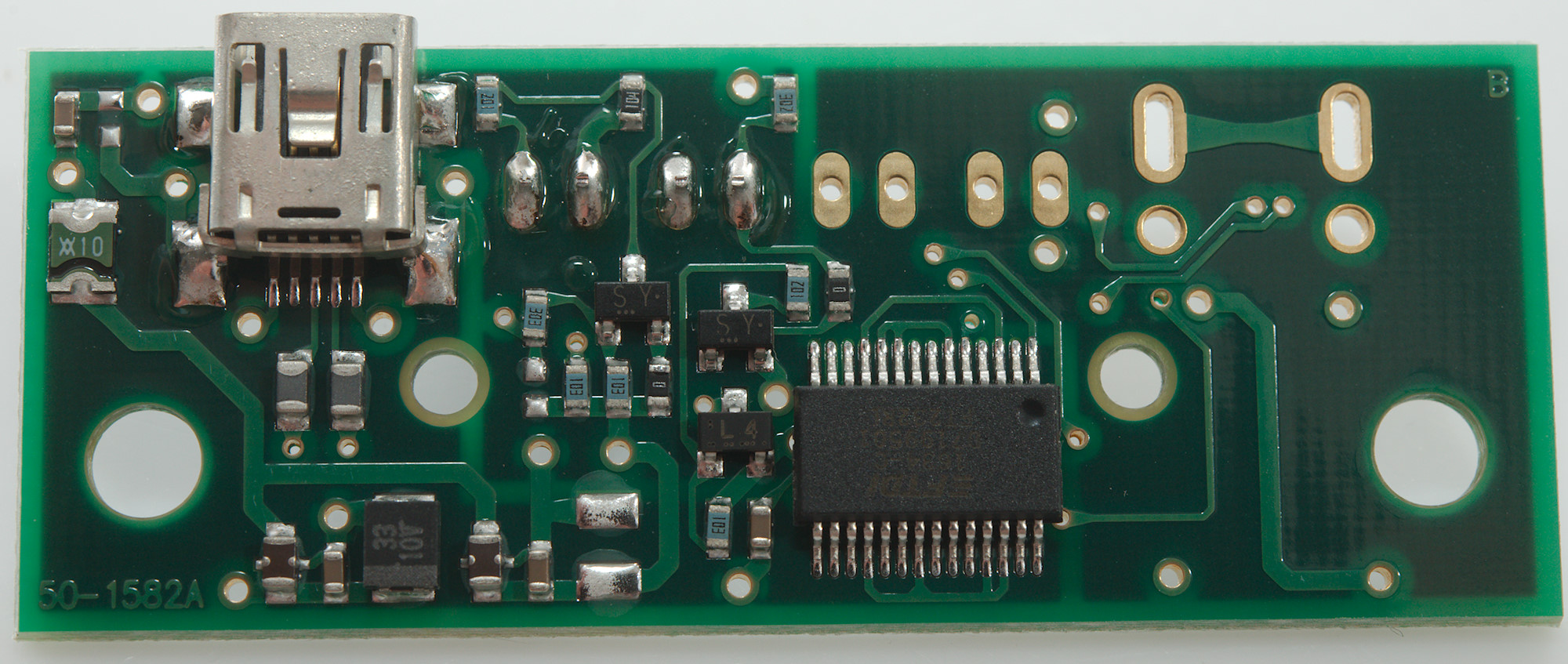
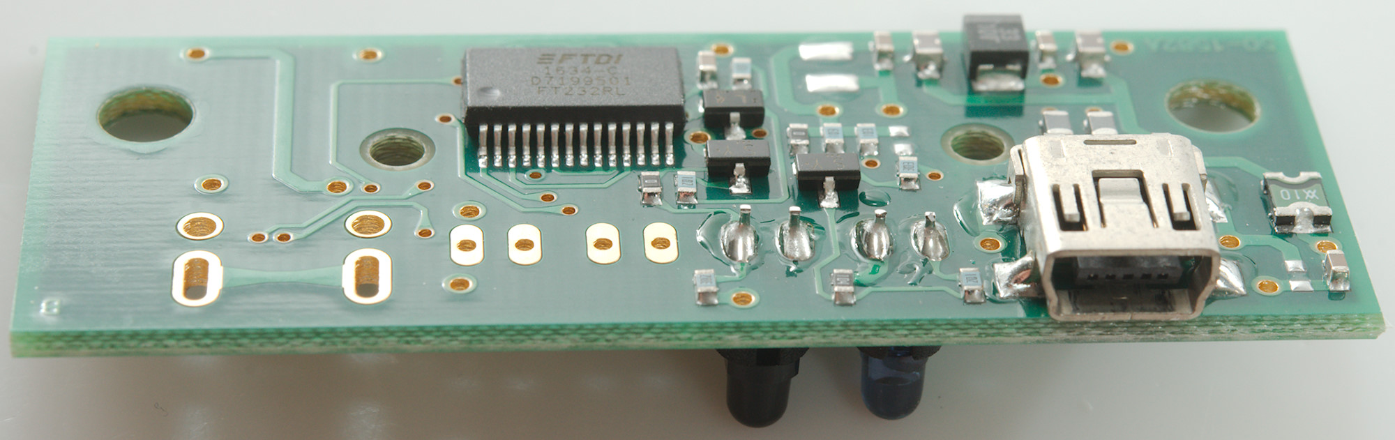
The circuit is a FTDI FT232RL chip with a few transistors. It uses a multilayer circuit board.


It looks like another circuit can be mounted on this side, mostly with transistors (I count 7) and no chip. I wonder if it can then be flipped and fit in the same enclosure.
Conclusion
This is a high end meter and has good input protection and lot of ranges and functions. The display could need a upgrade to a better one and the battery life is a bit short, especially in AC modes.
The button interface is a bit special with two shift buttons (SHIFT and MEMORY), but works fine enough after a bit of practice.
The meter has a unique function in that it can use either RMS or Mean for AC, I have not seen that before and am not sure it has any practical applications.
The computer interface is fairly expensive and the software is not very advanced, but at least the protocol is documented and it is simple. The actual hardware interface is a nice box with USB connector that is clipped onto the meter.
The precision is good and generally it works well.
Notes
This meter is similar to YOKOGAWA TY720
How do I review a DMM
More DMM reviews