DMM Mastech MS2108A
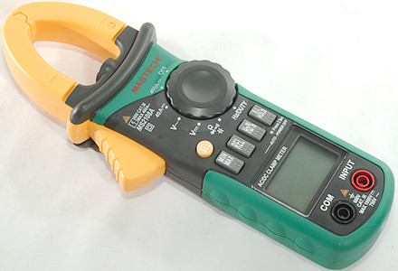
This is a AC/DC clamp meter.
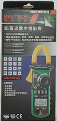
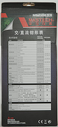
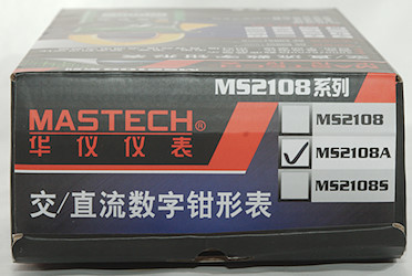
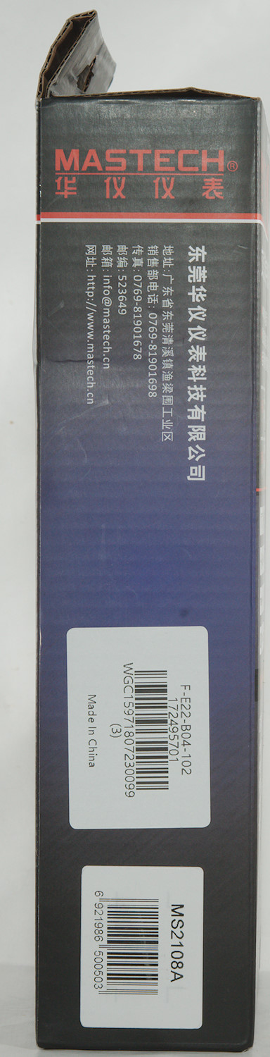
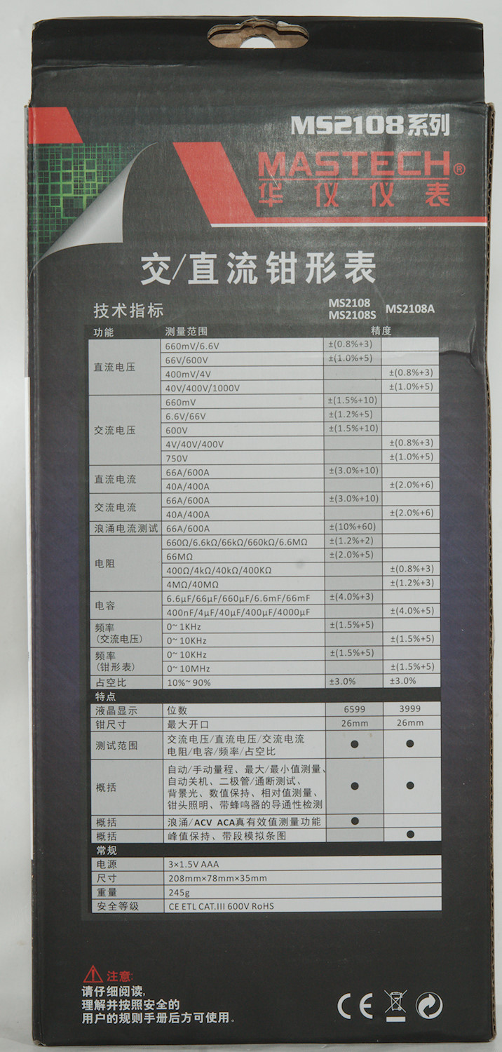
I got the meter in a cardboard box with specifications for the 3 meters in the MS2108 series.
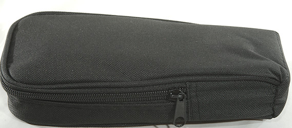
Inside the box was a pouch with everything in it.
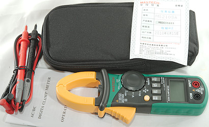
It included the DMM, a pair of probes, the bag and a instruction sheet.
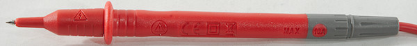
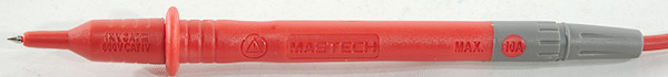
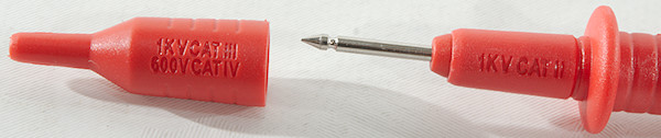
Probes are branded with Mastech and has removeable tip covers. The CAT rating is the usual CAT II without covers and III & IV with covers.
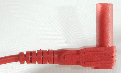
The plug is fully shrouded and standard probe plug size.
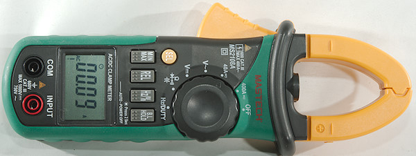
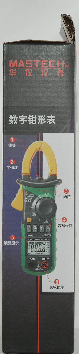
The meter is a clamp meter with the terminals for probes on the front.
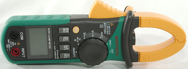
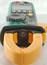
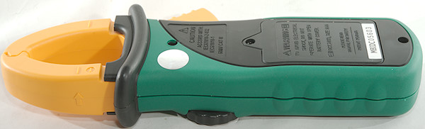
There is a led in the clamp, it will turn on together with the backlight, but only when meter is in current ranges.
Display
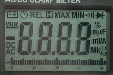
The above picture shows all the segments on the display.
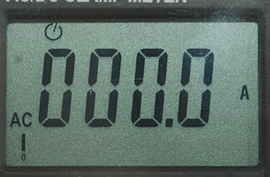
Typical display during usage, it will show the main number and what measurement is selected, together with the bargraph.
Functions
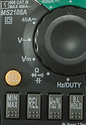
Buttons:
- Sel: Select DC/AC in current ranges and ohm/diode/continuity/capacitance in ohm range.
- Min/max: Capture minimum and maximum when active, it will change between max/min, hold down to disable.
- Rel: Shows values relative to current value
- Hz/%: Show frequency and duty-cycle in AC modes. This is also used in Hz mode to select duty-cycle.
- B.L Hold: Freezes the display, hold down to turn on backlight and flashlight in clamp (On in current modes).
MIN/MAX and REL will disable auto range while active.
Rotary switch:
- off: Meter is off
- 400A: High current range for AC and DC, uses the clamp
- 40A: "Low" current range for AC and DC, uses the clamp
- VAC: Voltage AC, frequency and duty cycle.
- VDC: Voltage DC
 : Resistance, diode, continuity and capacitance
- Hz/Duty: Logical frequency and duty cycle.
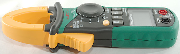
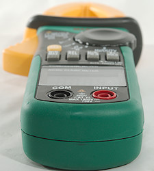
Input
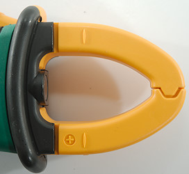
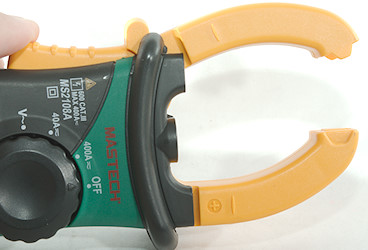
The clamp for current measurement.
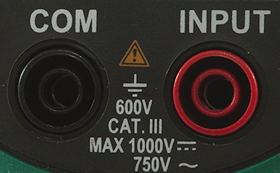
Voltage, frequency and ohm input terminals.
Measurements
- Volt and frequency
- Frequency input need the curve to reach within +/-0.5V of zero.
- At 0.1Vpp frequency input range is from 0.7Hz to 4.6MHz
- At 4Vpp frequency input range is from 0.5Hz to 22MHz
- Frequency in ACV requires a zero crossing.
- At 0.1Vpp input in ACV frequency range is from 1Hz to 22kHz
- At 4Vpp input in ACV frequency range is from 0.5Hz to 10MHz
- Duty cycle works from 5% to 95% at 100kHz with 2Vpp, precision is within 3.0.
- Duty cycle works from 2% to 95% at 10kHz with 1Vpp, precision is within 1.0.
- 1 VAC is 5% down at 2.4kHz
- Max/min needs about 200ms to capture a voltage, it needs multiple pulses before it will show the correct value.
- Input impedance is 10-11Mohm on DC and AC.
- mV DC is fairly high input impedance.
- Logical frequency input is down to 650ohm input impedance.
- Rated overload protection is 1000VDC 750VAC in voltage ranges.
- Rated overload protection is 250VDC/VAC in logical frequency ranges.
- Current
- Current ranges starts in AC
- As usual there is a offset on DC that needs to be cancelled with REL
- Clamp can handle ø22mm cables.
- Ohm, continuity, diode and capacitance
- Ohm needs about 2.9s to measure 100ohm
- Ohm is 0.44V open and 0.22mA shorted
- Continuity is moderate speed (About 140ms).
- Continuity beeps when resistance is below 40ohm
- Continuity is 0.44V open and 0.22mA shorted
- Diode range uses 2.9V, max. display is 1.999V at 0.39mA, max. current is 1.3mA shorted
- 4000uF takes about 30 seconds to measure.
- 10uF takes about 2.7 seconds to measure.
- Rated overload protection is 250VDC/VAC
- Miscellaneous
- Current consumption is 16mA with clamp active and 3.5mA or less in other ranges (50mA with clamp, backlight and flashlight).
- Meter works down to 1.8V where display starts to fade, battery symbol show at 3.6V.
- Voltage DC readings are correct down to 2V where the display locks with last reading.
- Clamp readings are correct down to 3.2V where the starts to drop very significantly.
- Backlight will fade with dropping battery voltage and is very dim at 2.7V
- The meter need a couple of updates before the reading is correct.
- Viewing angle is good
- Display updates around 3 times/sec
- Bargraph updates around 30 times/sec
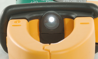
- There is a flashlight in the clamp, it will turn on/off together with backlight, but only in current mode.
- Backlight and flashlight will turn off in 27 seconds
- Will automatic turn power off in about 16 minutes
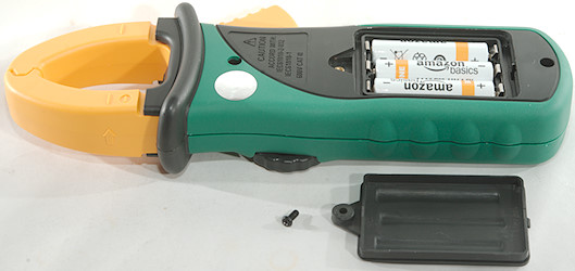
- Standard probes fits perfectly into sockets on meter.
- Weight is 278g without accessories, but with batteries.
- Size is 208 x 77 x 35mm.
- Probes
- Probe resistance 22mOhm for one.
- Probe wire is 81cm long.
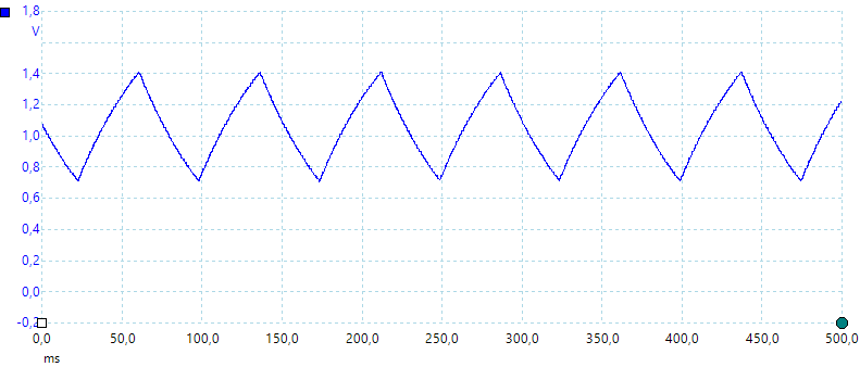
A look at the capacitance measurement waveform.
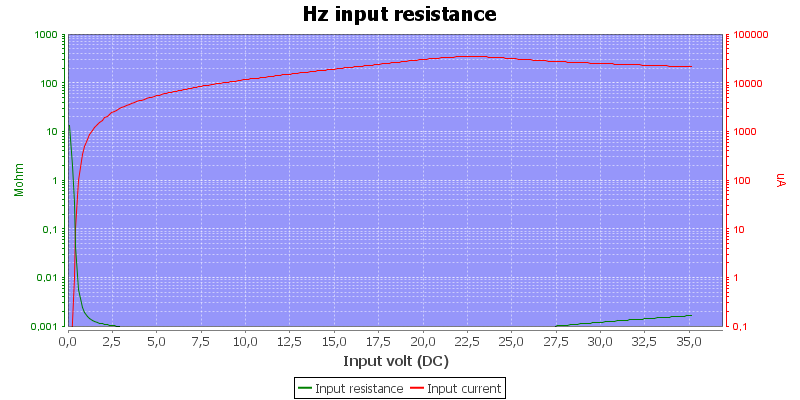
Frequency input resistance.
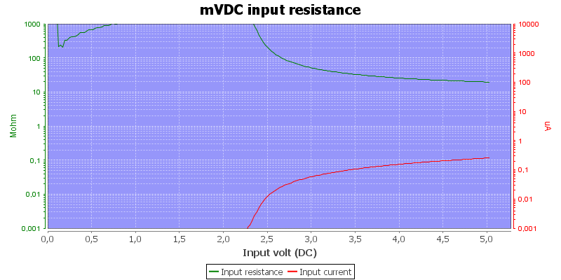
mV DC input resistance, range is locked with REL.
The offset at low capacity values are around 0.3nF
May show zero VAC when a large DC voltage is present together with the AC.
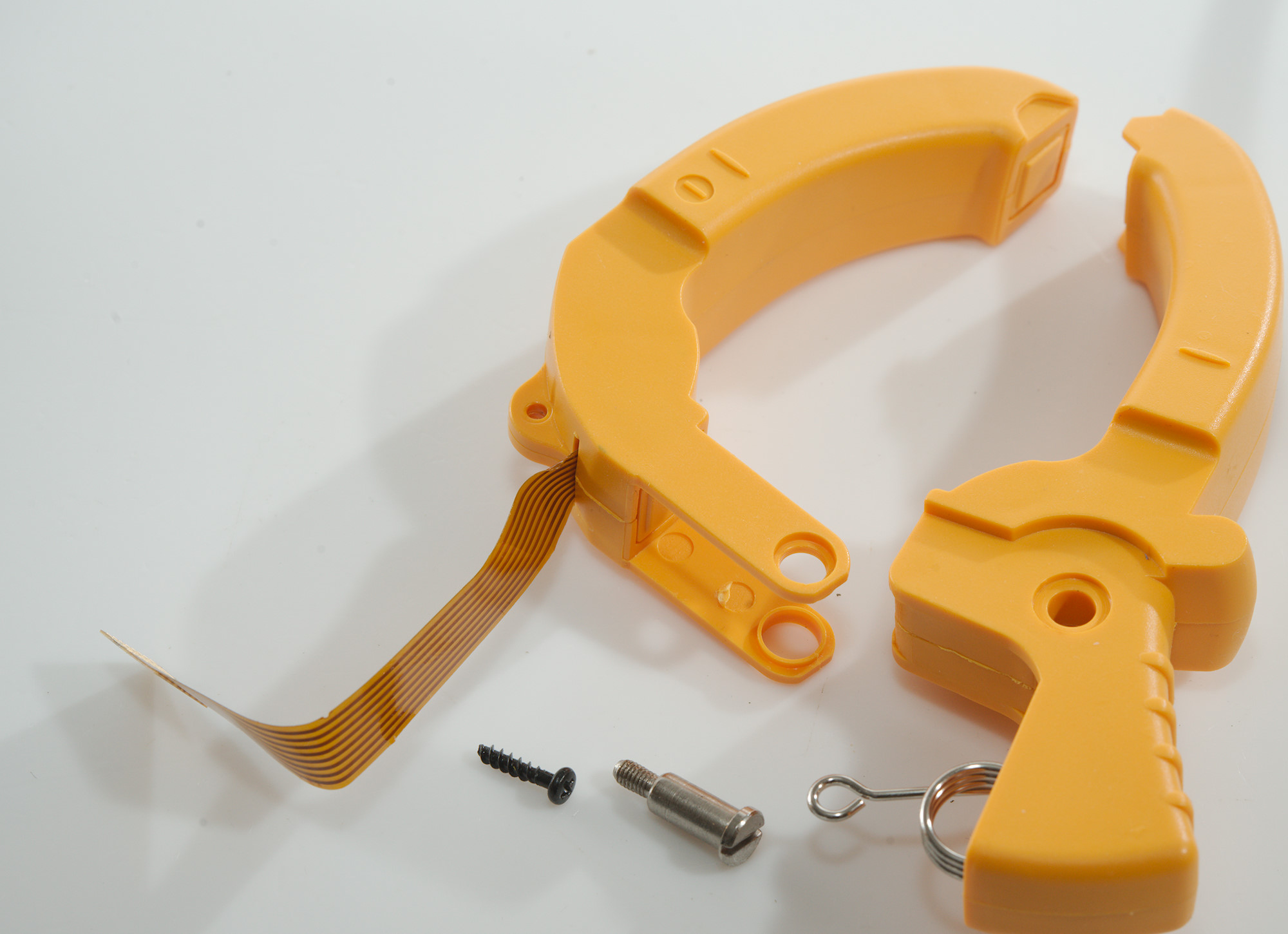
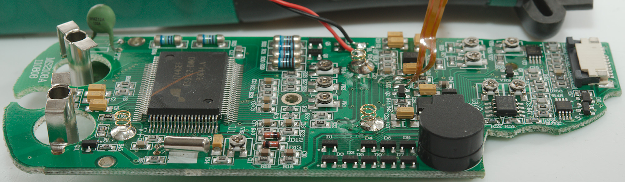
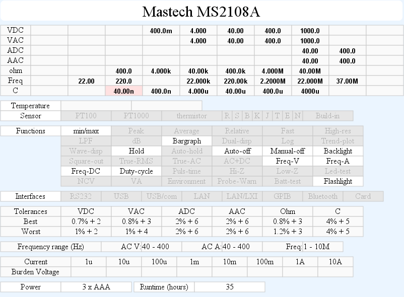
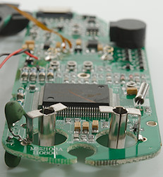
Tear down
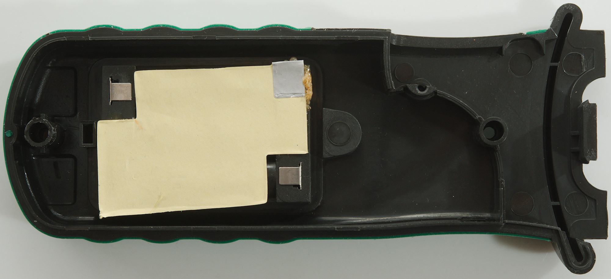
Removing two screws and I could open the meter.

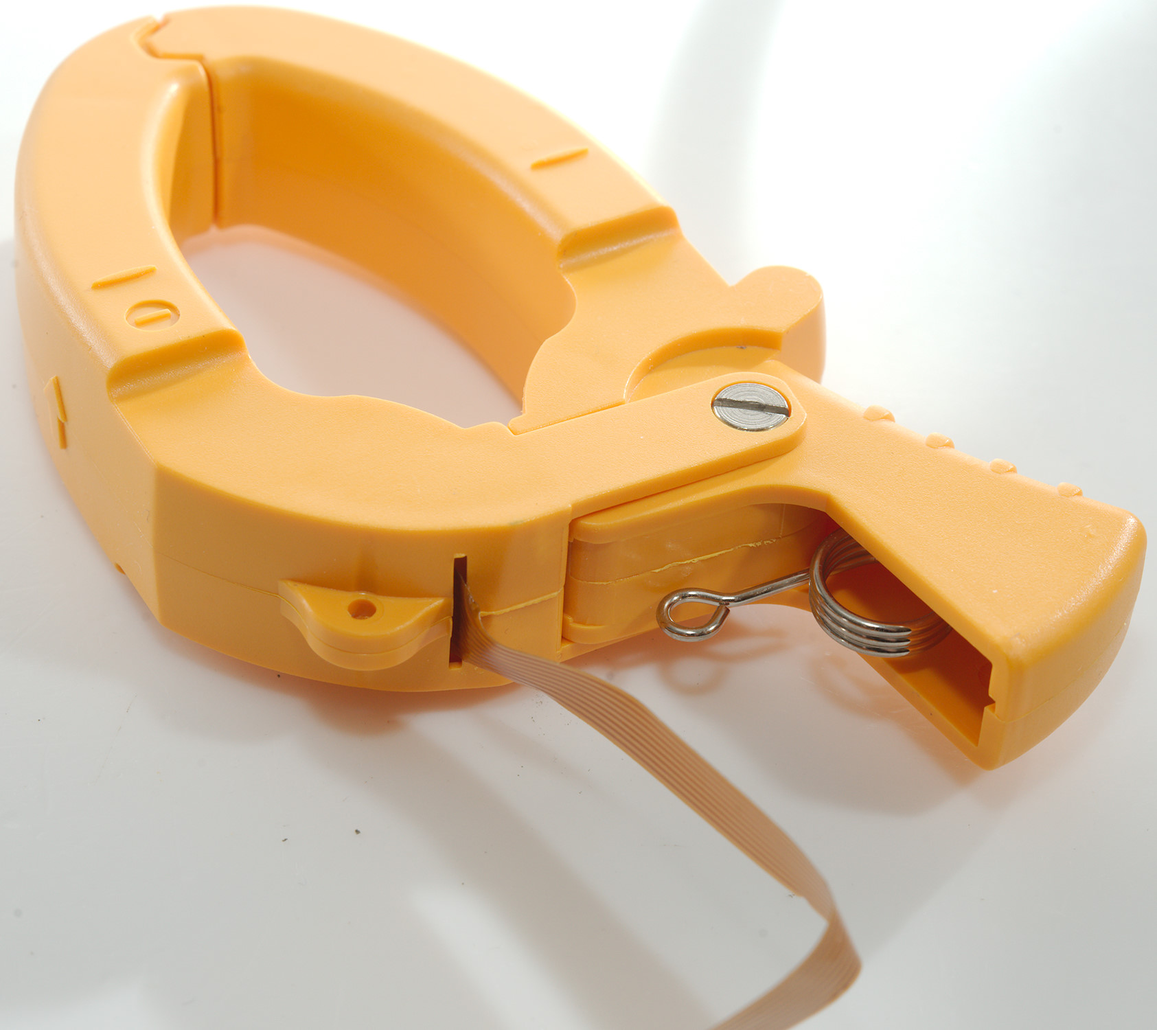
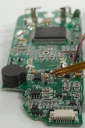
Notice the spring to keep the clamp closed.

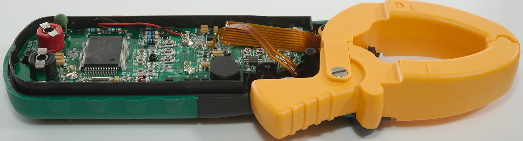
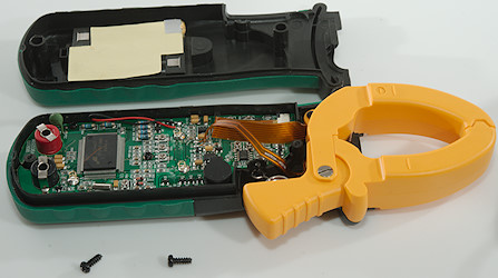
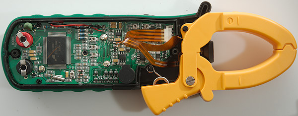
Removing one screw and loosing the hinge screw in the clamp and it could be removed.

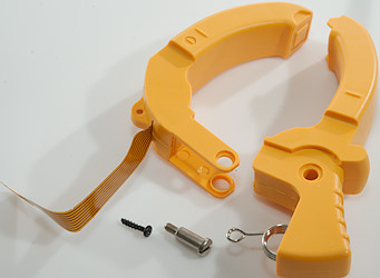
There is a flat flex cable from the sensors inside the clamp.
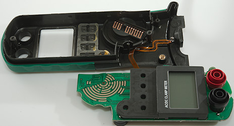
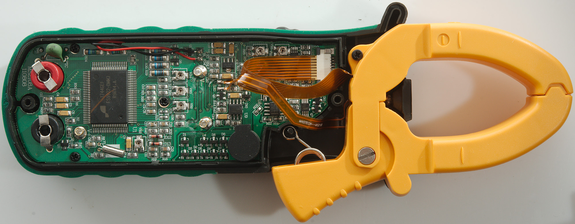
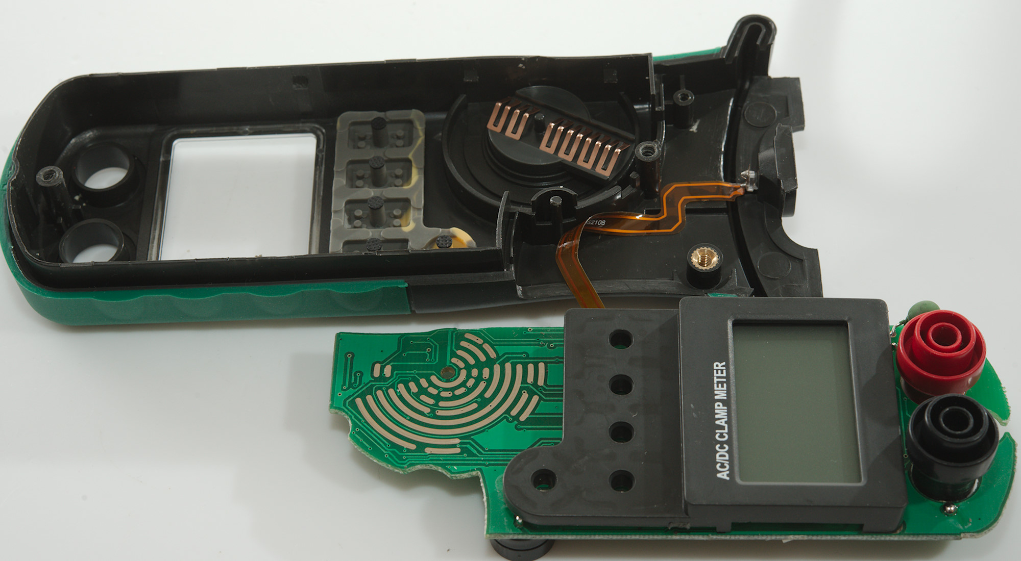
The electronic is secured with clips and could be removed, there is a flat flex cable to the flashlight led, it is soldered in both ends and also partly glued to the enclosure.
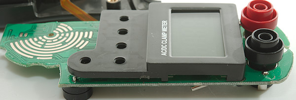
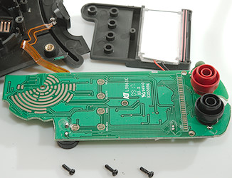
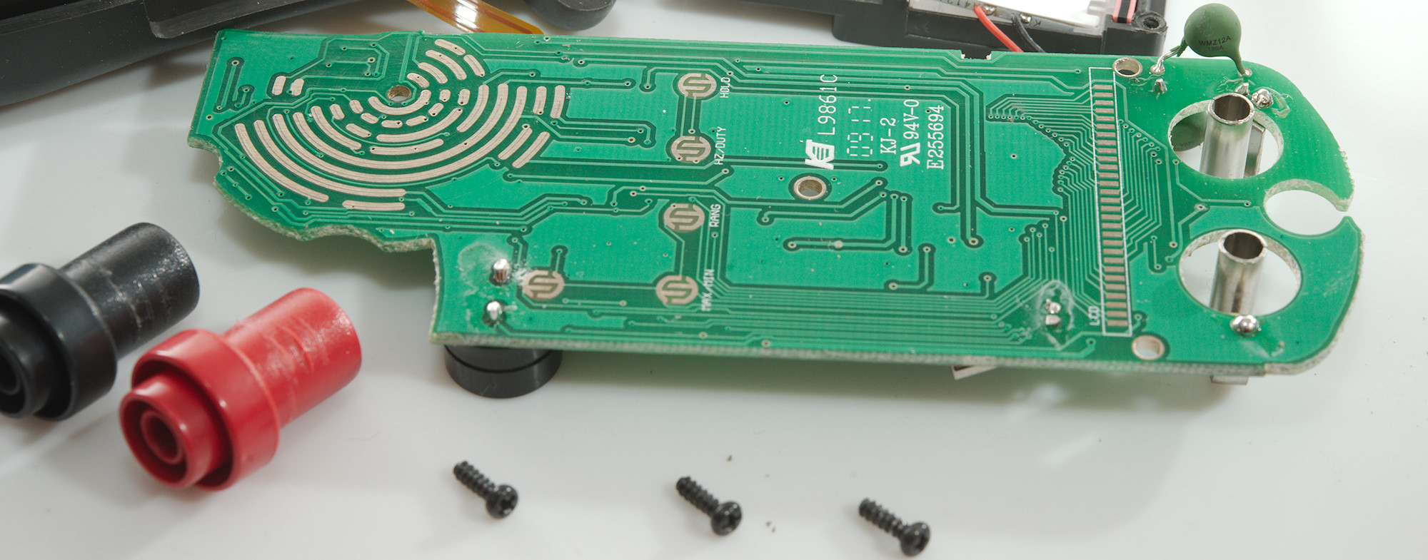
Removing 3 screws and the display could be removed.

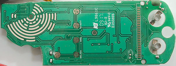
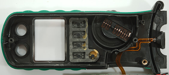
This side has the pads for the rotary switch, the buttons and the lcd. The REL pad is marked RANG (Sounds more like range). It also has one of the input PTC's.
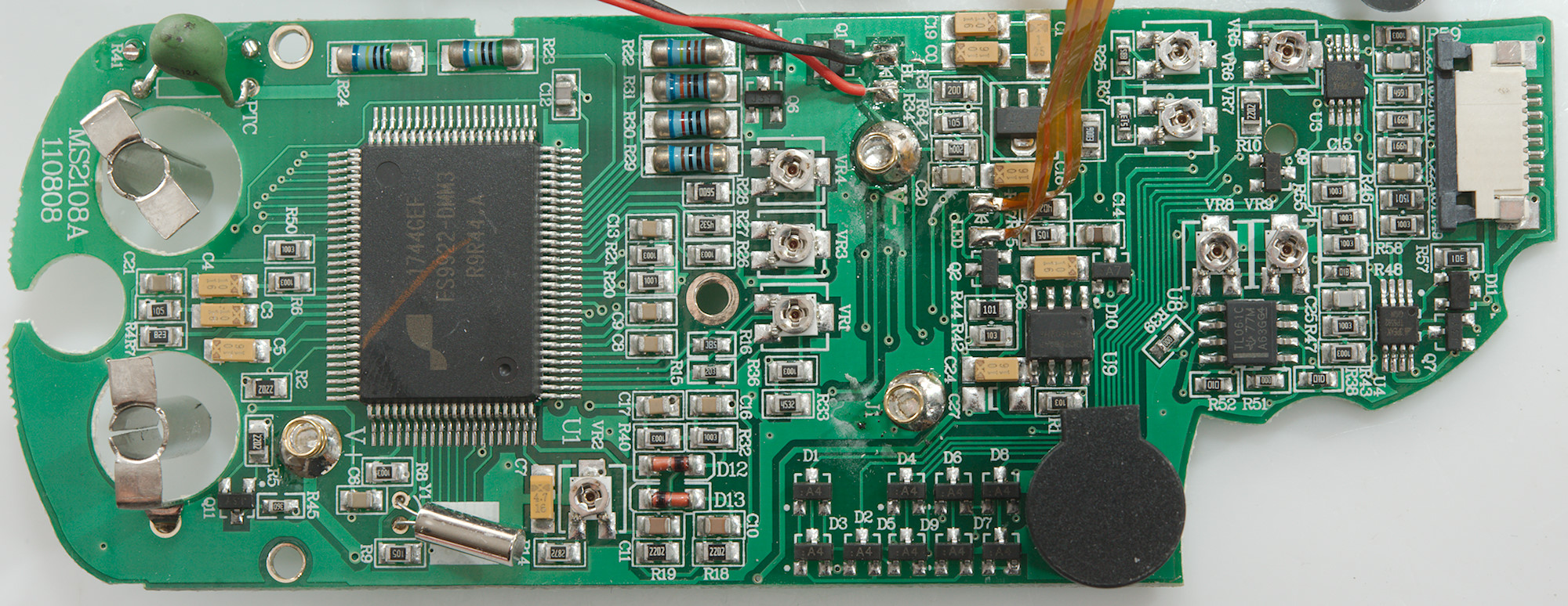
Voltage input has two paths each with a PTC in series. Voltage input uses a 10Mohm input path (R32 & R24: 2x5Mohm), in ohm a transistor pair (Q5 & Q6) adds protection, there is also the usual small SMD resistor (R13: 900kOhm). In Hz mode a diode is used for protection (D10). The meter part has a couple of trimpots (VR1..VR4).
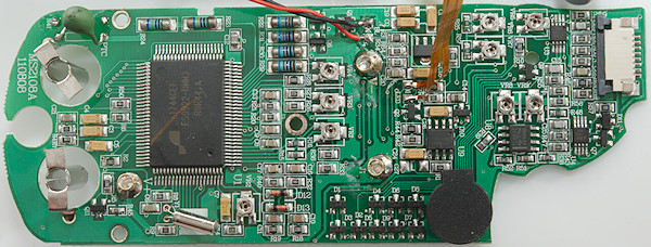
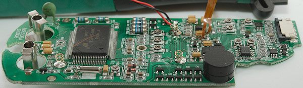
The input circuit from the clamp uses OpAmps (U3 & U4: TP5592 zero drift, U8: TL061C), there is a lot of trimpots (VR5..VR9) for adjustment of the clamp. To supply the OpAmps with a negative voltage there is a capacity voltage booster (U9: GC7660AP). The internal supply is stabilized by a voltage regulator (U2: Marked N35/OPB7O).
The large collection of diodes (D1..D9) is probably used for matching the range switch and buttons to the multimeter IC (FS9922-DMM3).
Conclusion
The input protection will not handle high voltage transients without damaging the meter.
For people needing to measure high AC or DC current this meter looks acceptable and with min/max function it is also possible to capture the highest values. The multimeter functions are fairly average with a good bargraph. I do not like the very low input impedance on logical frequency (650ohm), Most meters have low input impedance, but more like 2kOhm.
Notes
How do I review a DMM
More DMM reviews