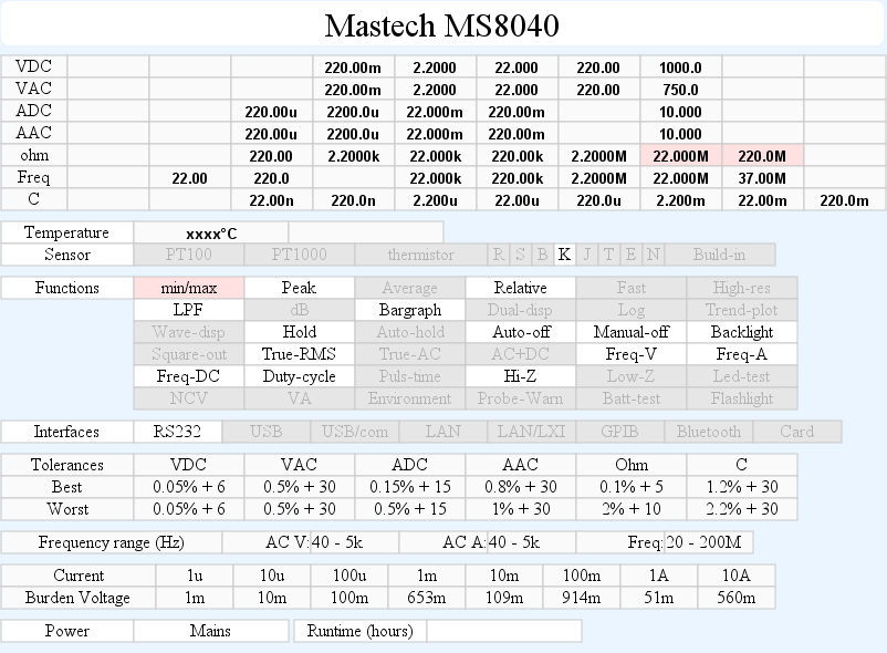
DMM Mastech MS8040
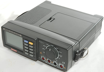
This is a bench meter from Mastech. This type of bench meter is basically a handheld meter put into a bigger enclosure with a mains power supply added.
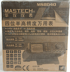
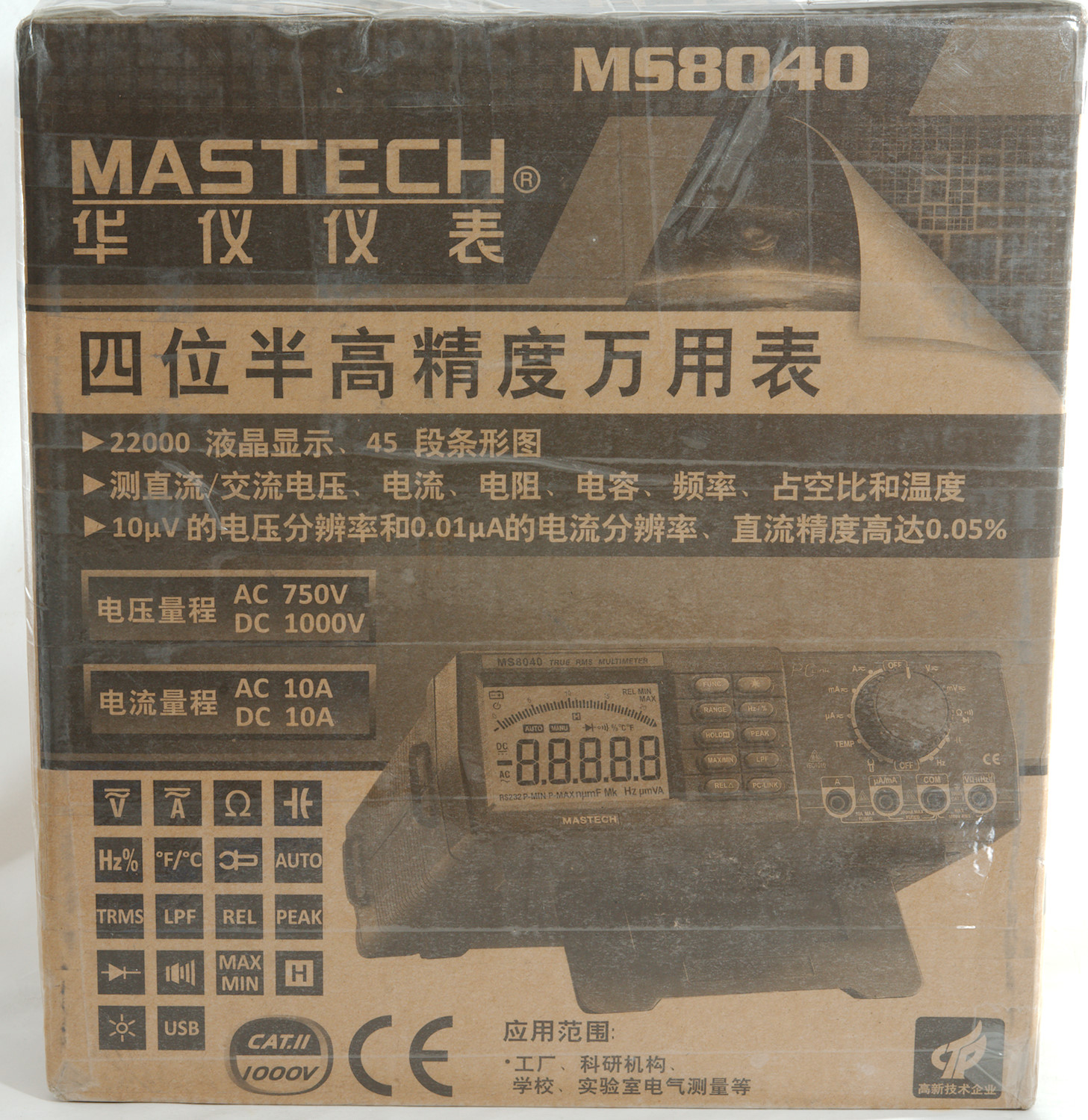
The meter was shipped in its box, only wrapping was a layer of sticky tape.
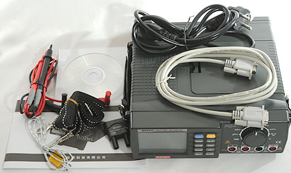
There was a lot of stuff in the box: The meter itself, a mains cable, a RS232 cable, probes, thermocoupler, adapter for thermocoupler, manual and a CD.
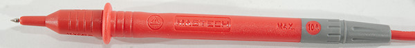
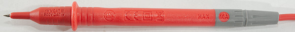
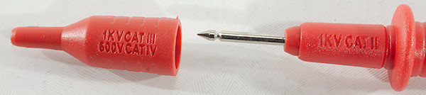
Probes are branded with Mastech and has removable tip covers. The CAT rating is the usual II without covers and III & IV with covers.
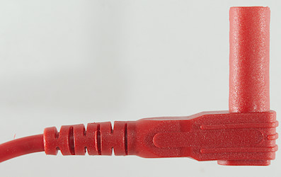
The plug is fully shrouded and standard probe plug size.
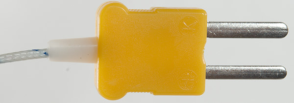
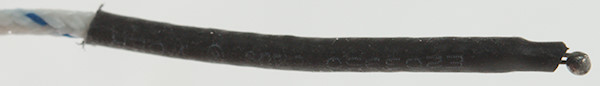
The thermocoupler is standard type with standard thermocoupler plug (Except the pins are too long).
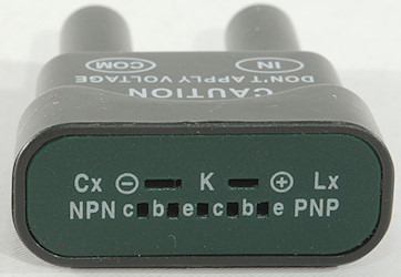
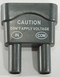
With this type of thermocoupler plug a adapter is needed, this adapter can also be used for capacitors and resistors.
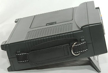
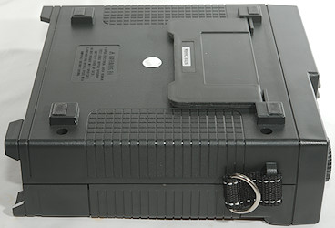
The tilting bale only support one position.
The meter is heavy and large enough that both the rotary switch and the buttons can be used by one hand.
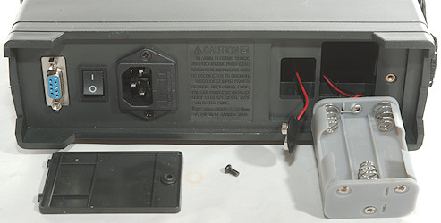
This meter can either use mains power or battery power and battery can be either 6xAA or one 9V.
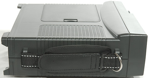
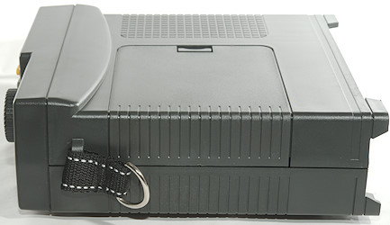
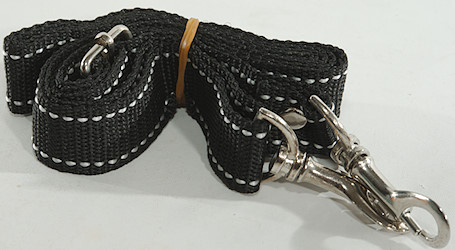
The meter has a handle one on side and a shoulder strap is also supplied.
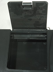
There is a lot of empty space inside the meter, some of it can be used to store accessories.
Display
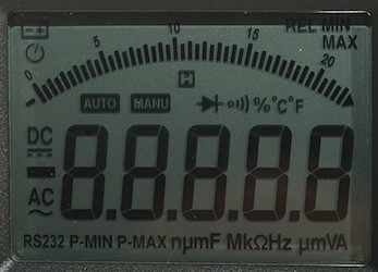
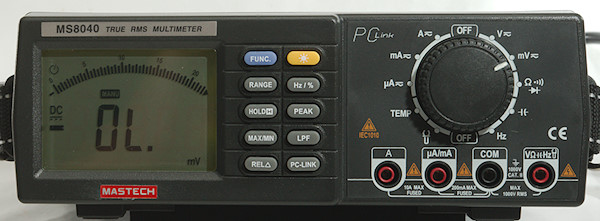
The above picture shows all the segments on the display. There is missing a icon for LPF (Low pass filter)!
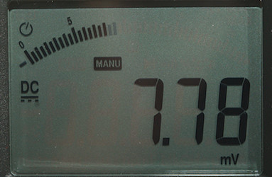
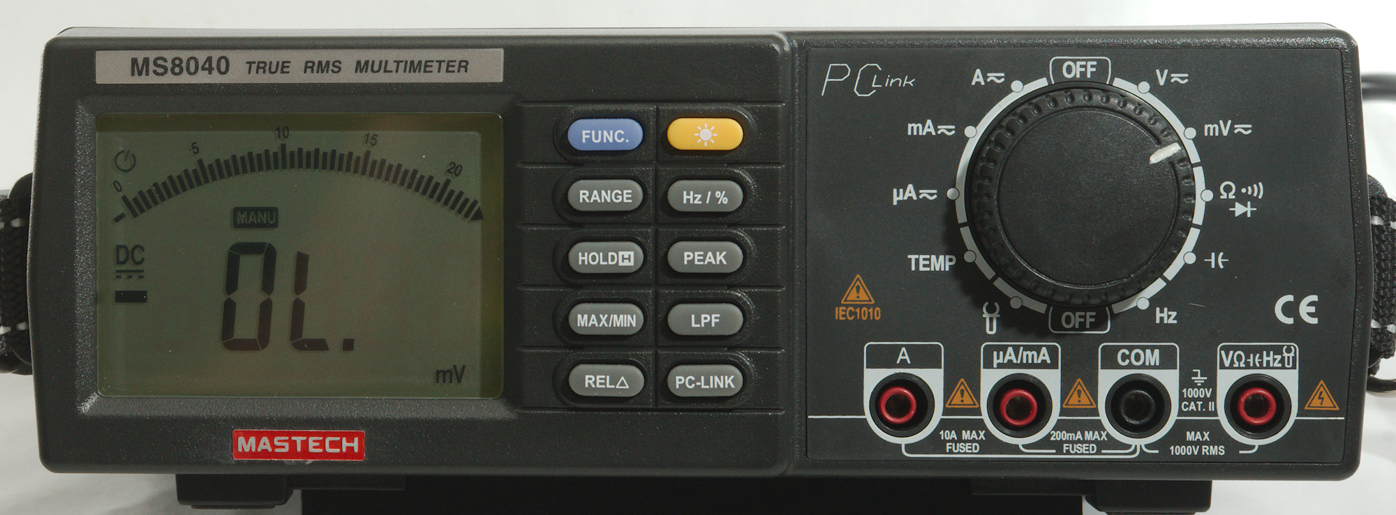
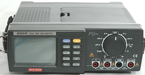
Typical display during usage, it will show the main number and what measurement is selected.
Functions
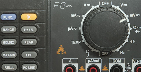
Buttons:
- Func (Blue): Select between the different modes on each position of the range switch.
 : Turn background light on, this will automatic turn off again!
- Range: Manual range selection, hold down to return to automatic ranging.
- Hz %: Select frequency and duty cycle display in voltage and current modes, in frequency mode it will select duty cycle.
- Hold: Freezes the display
- Peak: Capture peak voltages
- Max/min: Select max/min mode, press to toggle between max/min/current, hold down to disable again. To reset turn meter off for some time.
- LPF: Enable low pass filter in voltage AC, the only indication it is activated is that the meter changes to manual ranging.
- Rel: Shows values relative to current value
- PC-Link: Enable data output, this will also disable auto power off.
Peak, max/min, LPF and Rel will all select manual ranging.
Rotary switch:
- Off: Meter is off, but power supply is on
- V: VDC and VAC, use FUNC to select DC or AC.
- mV: Millivolt DC and AC, use FUNC to select DC or AC.
 : Resistance, continuity and diode
 : Capacitance
- Hz: Logical frequency, this range requires square wave input and will show duty-cycle (use Hz).
- Off: Meter is off, but power supply is on
 : Show voltage and current, used for external clamp. The clamp must be 1mV/A
- Temp: Temperature input with thermocoupler type K.
- uA: Microampere range, use FUNC to select DC or AC.
- mA: Milliampere range, use FUNC to select DC or AC.
- A: Ampere range, use FUNC to select DC or AC.
Input
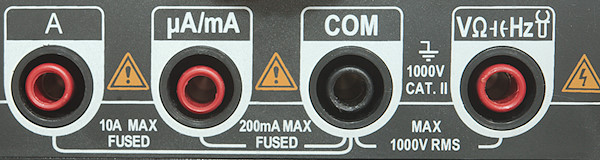
- A: High current, maximum current is 10A
- mAuA: The lower current ranges.
- CON: The common terminal for all ranges.
- xxx: All other ranges.
Measurements
- Volt and frequency
- Frequency input can count 1Vrms with a DC offset of at least +/-8.5V
- At 1Vrms frequency input range is from 3Hz to 37MHz
- Duty cycle works from 5% to 95% at 100kHz with 2Vpp, precision is within 0.8.
- 1 VAC is 5% up at 38kHz (RMS will not work at the frequency).
- With LPF activates 1 VAC is 5% down at 650Hz
- LPF do not always activate when LPF button is pressed, check meter changes to manual (MANU) range when pressing button
- Max/min needs about 350ms to capture a voltage, turning it off will not reset captured value.
- Max/min can show max/min/current value
- Peak captures min and max values, it needs about 0.7ms to capture a voltage,
- Input impedance is 10-11Mohm on DC/AC
- Millivolt input impedance is high for both DC and AC up to about 3V where it drops to about 100kOhm
- Maximum voltage is not specified in manual, but meter says 1000VDC/AC.
- Current
- Overload protection in uA and mA (Fuse 2): 0.4A/250V 6.3x32mm fuse (Manual says 0.3A)
- Overload protection in A (Fuse 1): 10A/250V 6.3x32mm fuse
- To replace fuses the meter must be taken apart.
- Ohm, continuity, diode and capacitance
- Ohm needs about 1.4s to measure 100ohm
- Ohm is -0.4V open and -1.6mA shorted
- Continuity is very fast (About 1ms).
- Continuity beeps when resistance is below 30ohm
- Continuity is -3.0V open and -1.6mA shorted
- Diode range uses 2.8V, max. display is 1.8997V at 0.6mA, max. current is 1.8mA shorted, bargraph works up to 2.2V
- 70000uF takes about 11 seconds to measure.
- 10uF takes about 0.7 seconds to measure.
- Rated overload protection is 250VDC/VAC
- Miscellaneous
- Power consumption from mains when off is 0.8 watt
- Power consumption from mains when on without background light is 0.9 watt
- Power consumption from mains when on with background light is 2.3 watt
- On battery current consumption of meter is 6mA to 7mA with backlight it is 42mA
- Meter works down to 3.4V where it turns off, battery symbol show at 7.5V.
- Below 4.5V on the battery, the readings will change very significant (About 40% when meter turns off).
- Backlight will fade with dropping battery voltage and is completely out at around 5.7V
- The display is usual correct on first or second update.
- Viewing angle is good
- Display updates around 2 times/sec
- Bargraph updates much faster than numbers (At least 15 times/sec)
- Backlight will turn off in 58 seconds
- Will automatic turn power off in about 15 minutes.
- Standard probes fits perfectly into sockets on meter.
- The transformer has a low level hum when on.
- Weight is 1300g without accessories and batteries
- Size is 237(width) x 233(depth) x 80mm.
- Probes
- Probe resistance 20mOhm for one.
- Probe wire is soft and 81cm long.
- Communication cable is 191cm long
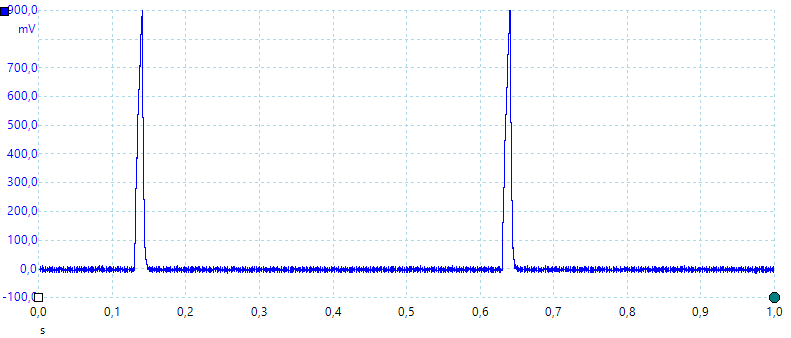
A look at the capacitance measurement waveform.
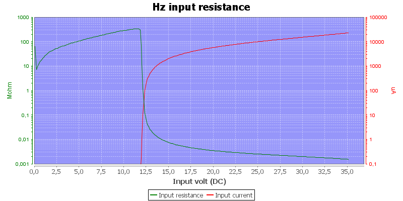
Frequency input resistance.
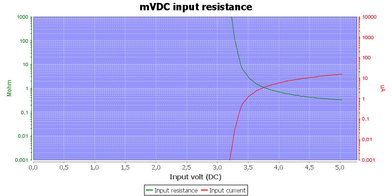
DC millivolt input resistance.
Display is a bit unstable in the high megaohms (10M+) and will not always be within tolerance.
A large DC voltage can block for AC voltage readings.
The VAC ratings are only valid from 20% of range, this is not very good.
Software
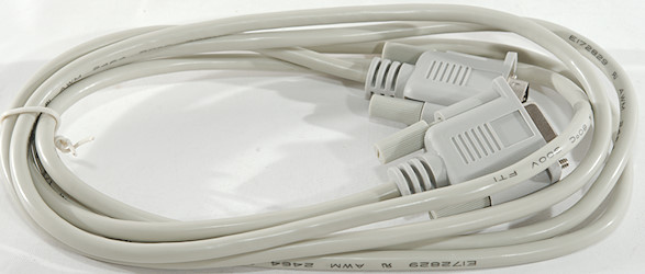
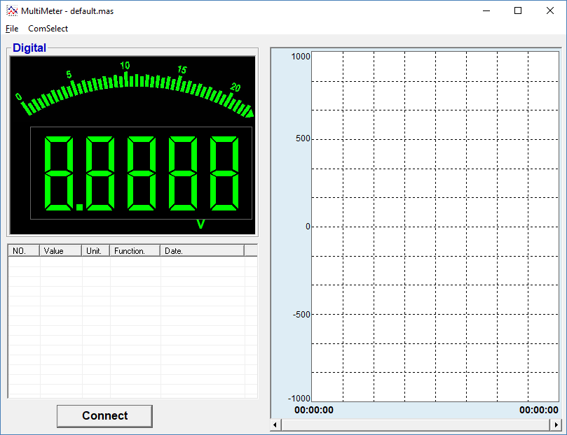
The software is supplied including a RS232 cable, the files on the CD is dated 2008, but there was no problems installing in Win10. The program is called "Multimeter", not the best name if you have more than one meter. Software support from COM1 to COM10, not perfect, but usable.

When starting the software looks this way on a Windows 10 computer. Everything is in this view, there is no other screens (Except save and load dialogs).
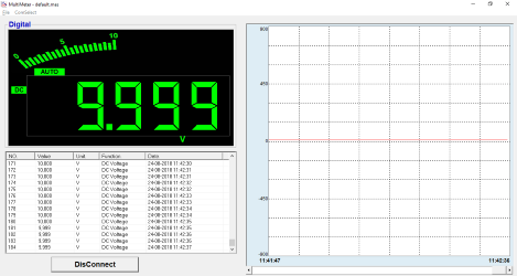
It can be maximised to fill the entire screen. The display shows actual value, a log and a chart, but the scale starts at +/-1000, this makes it rather difficult to see much.
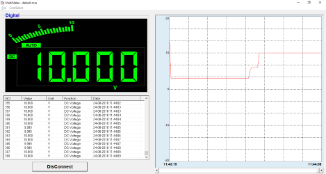
Using the left and right mouse buttons it is possible to zoom the chart in/out in this sequence:
1000-900-700-600-500-400-300-200-100-90-80-70-60-50-40-30-20-10-9-8-7-6-5-4-3-2-1
It requires some clicks to change the scale, but it works fairly well.
It is possible to save a "MAS" file, this is all data and can be loaded again to look at the data in this software.
There is also an "Export" option that saves in "xls" format. Excel will read the file, but do not show any data.
Tear down
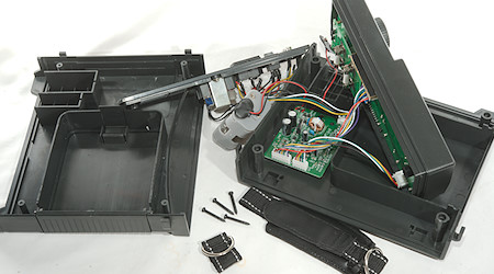
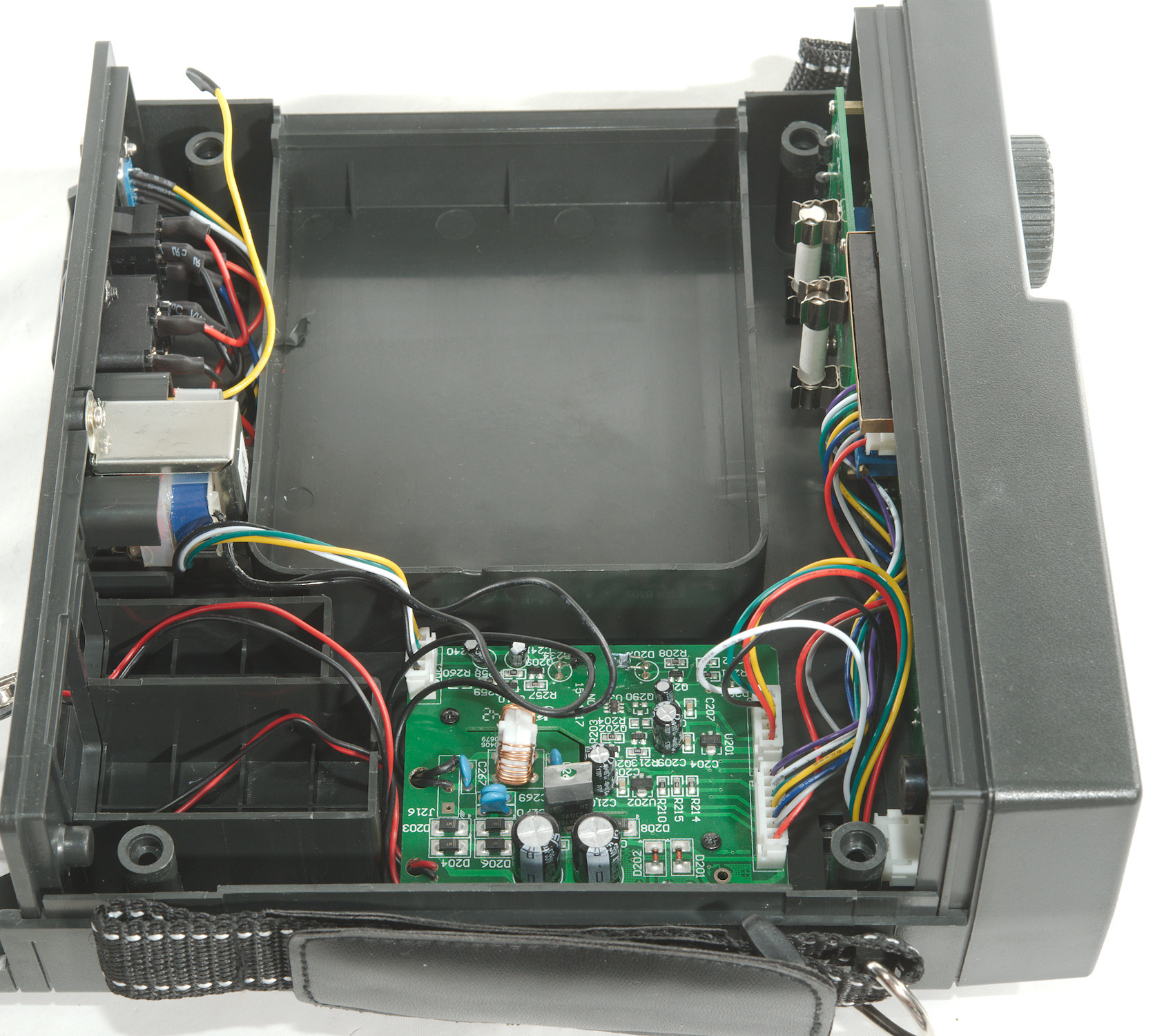
I had to remove four screws from the bottom of the meter to open it. It came apart in many parts with wires between some of them. Most wires has connectors and could be disconnected, but not all.
After removing the screws, but before opening the meter, turn it around, then it is much easier to keep track of the parts.
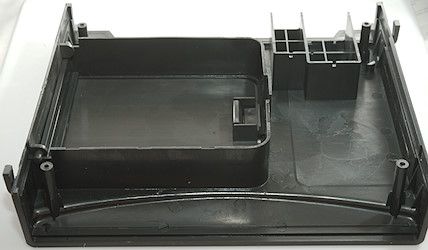
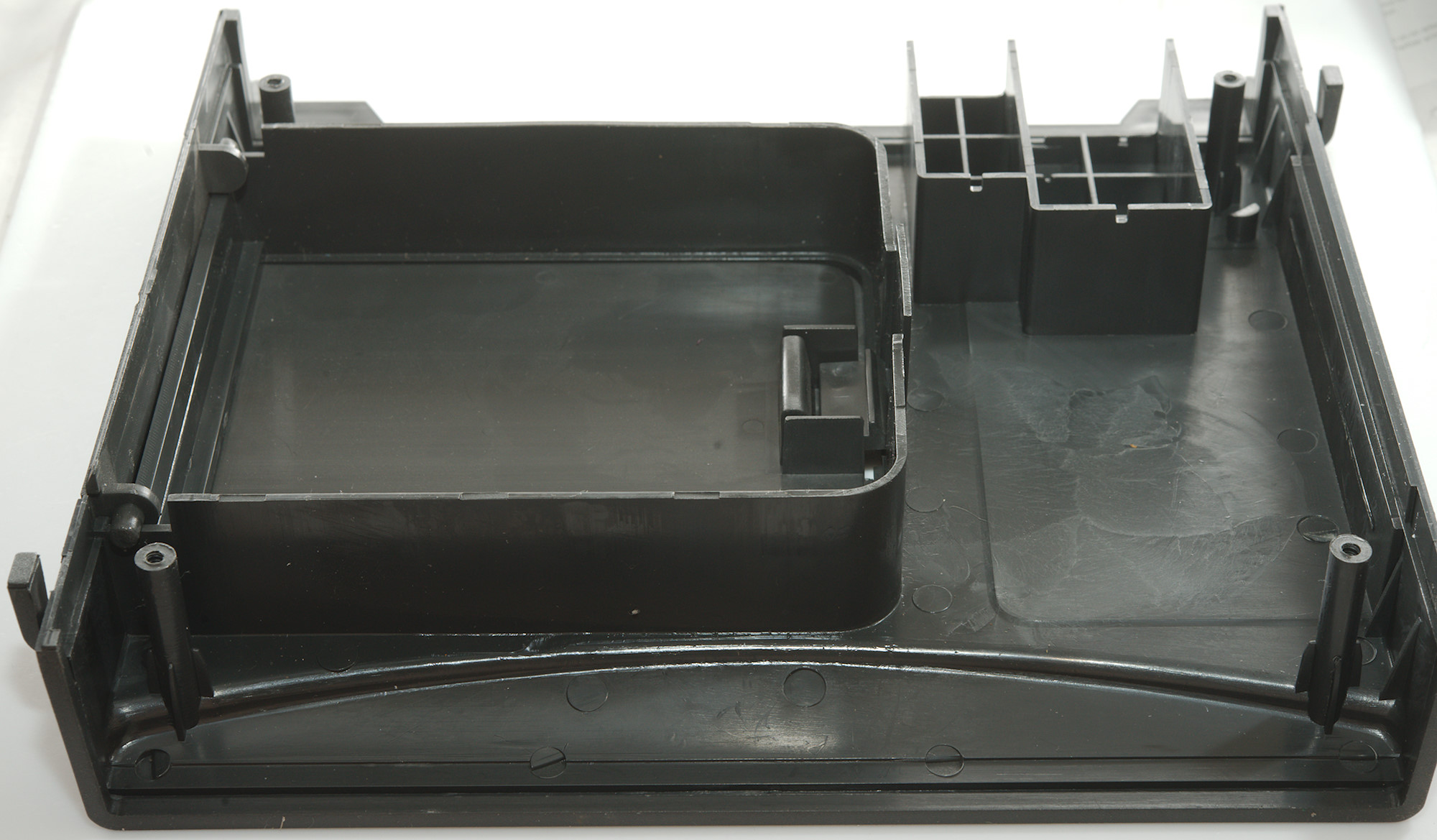
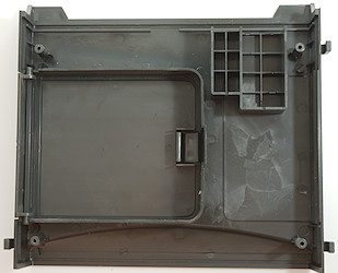
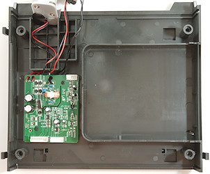
The top is empty, there are only the moldings for the storage compartment and the two batteries.
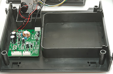
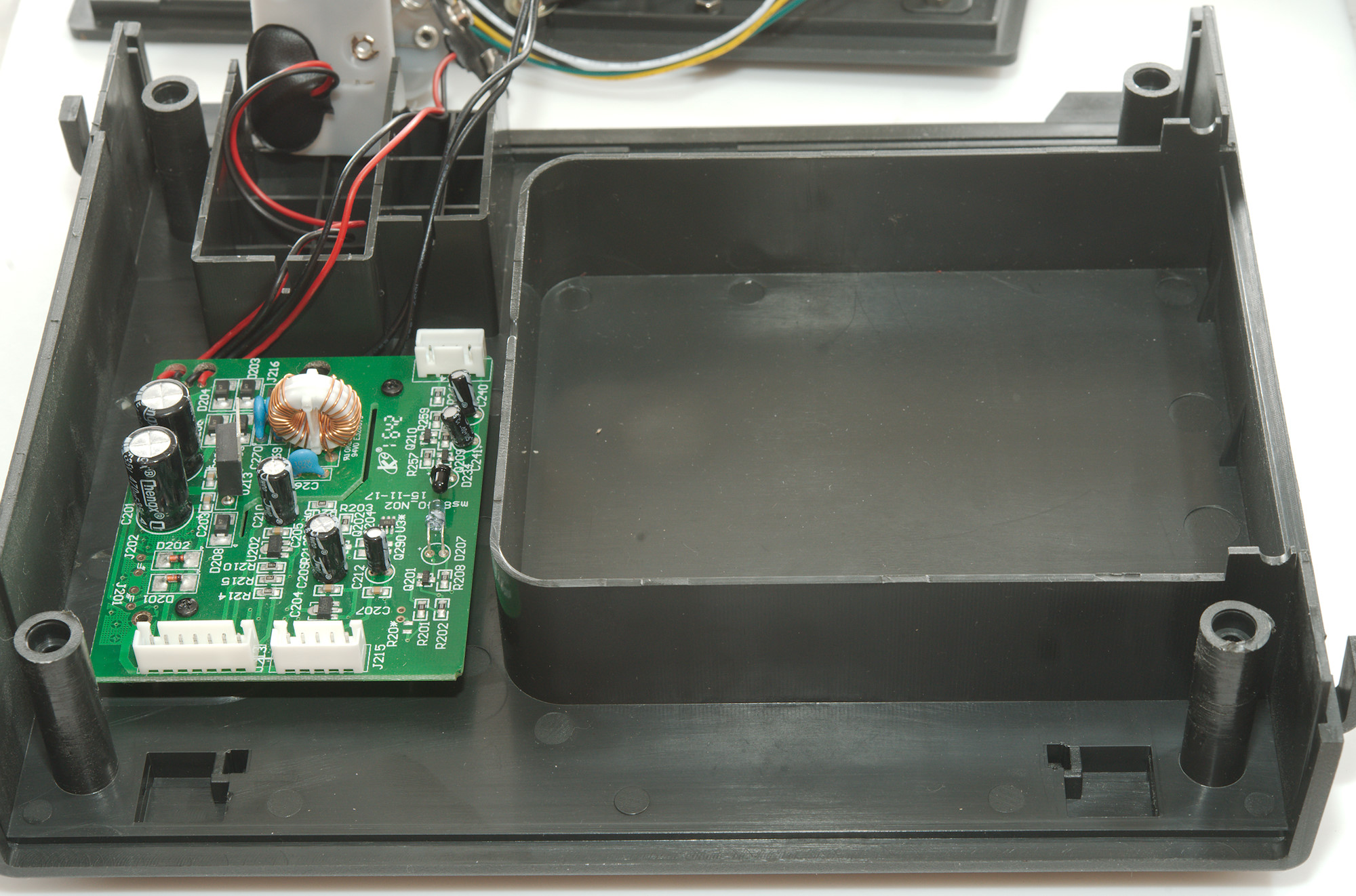
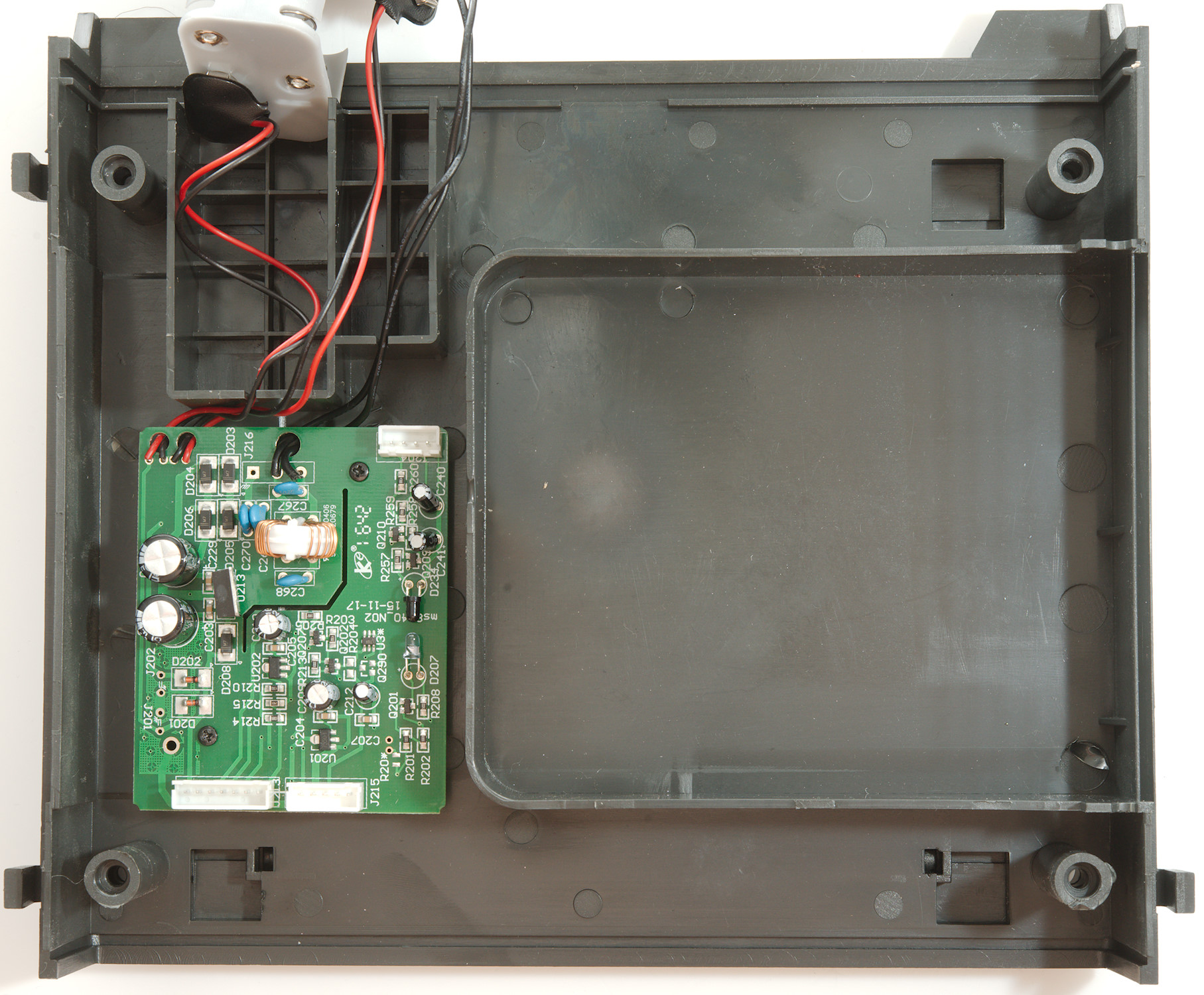
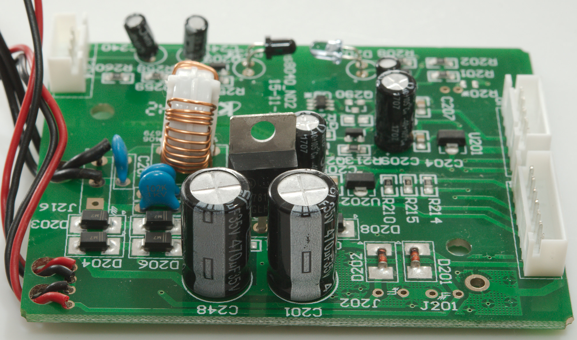
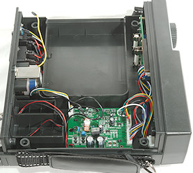
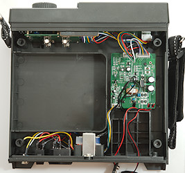
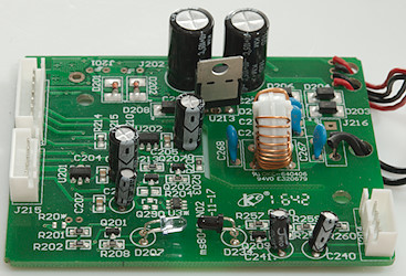
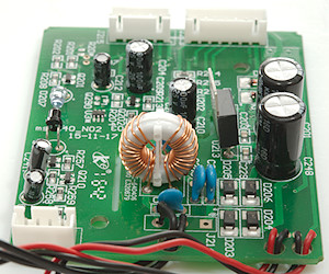
The bottom has the power supply and more board.
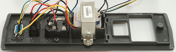
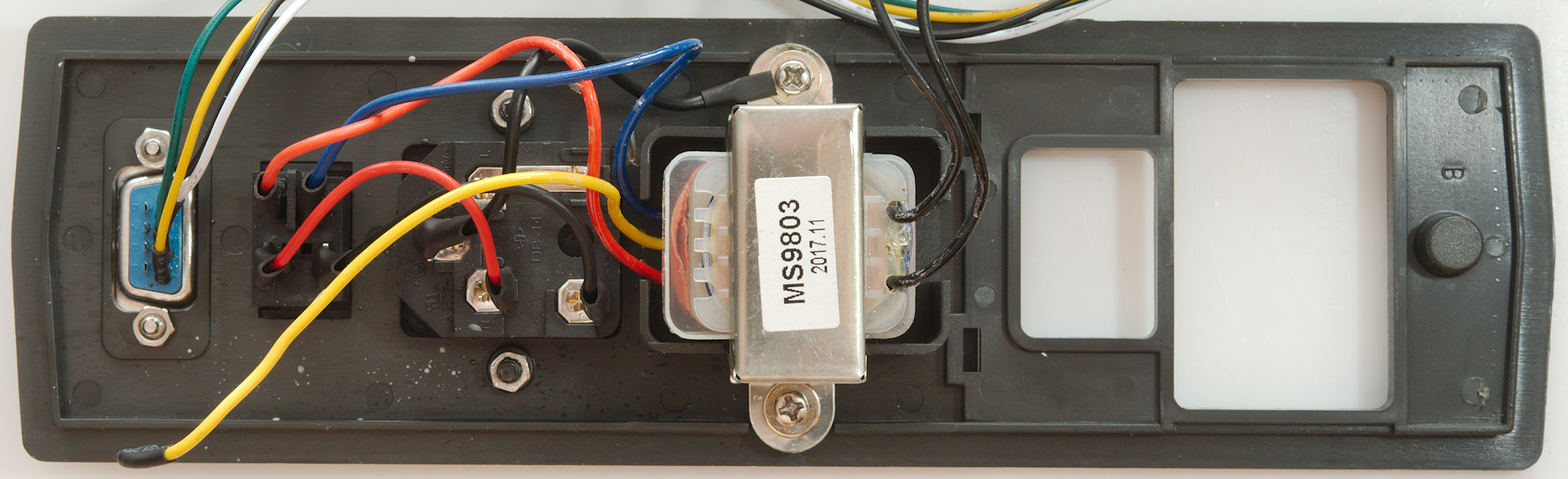
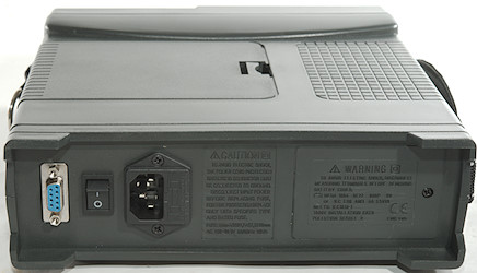
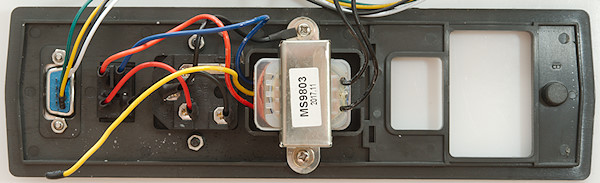
On the back is the mains inlet, the fuse, the transformer and the RS232 socket. The unconnected yellow wire is probably for 120VAC (i.e. swap yellow and blue (or red) for a 120VAC model).
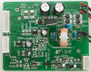
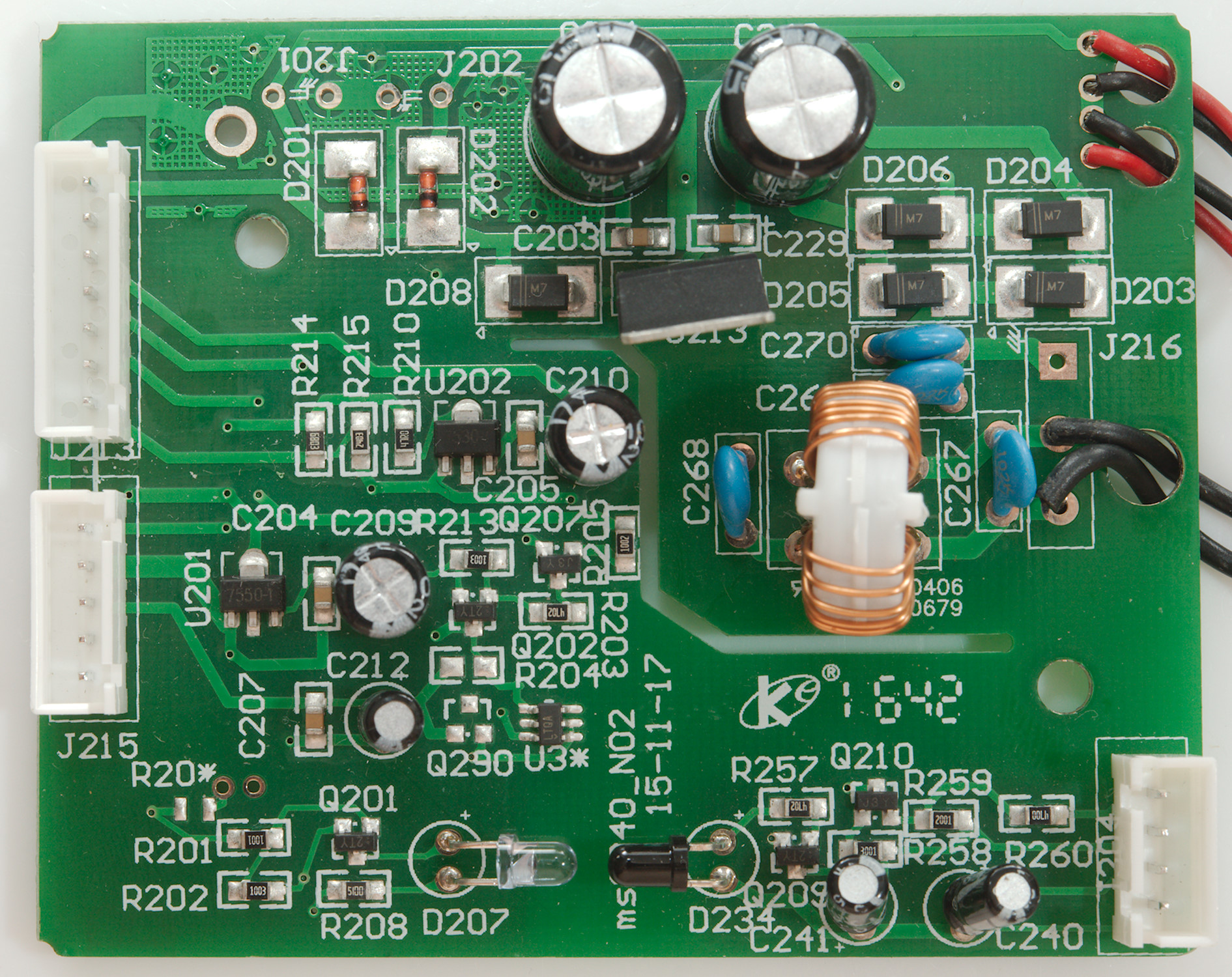
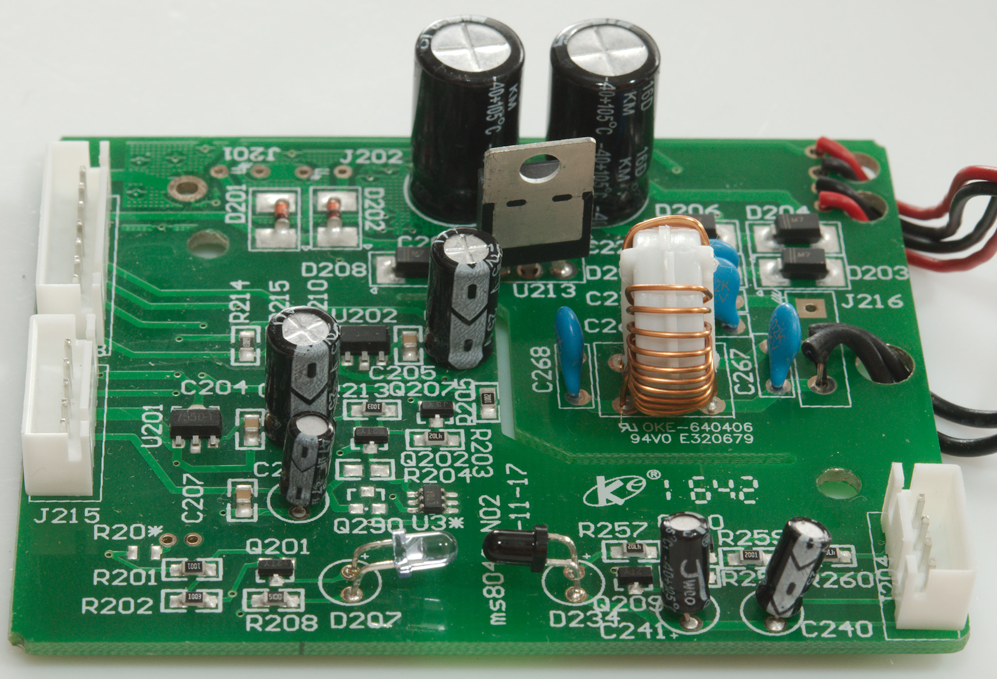
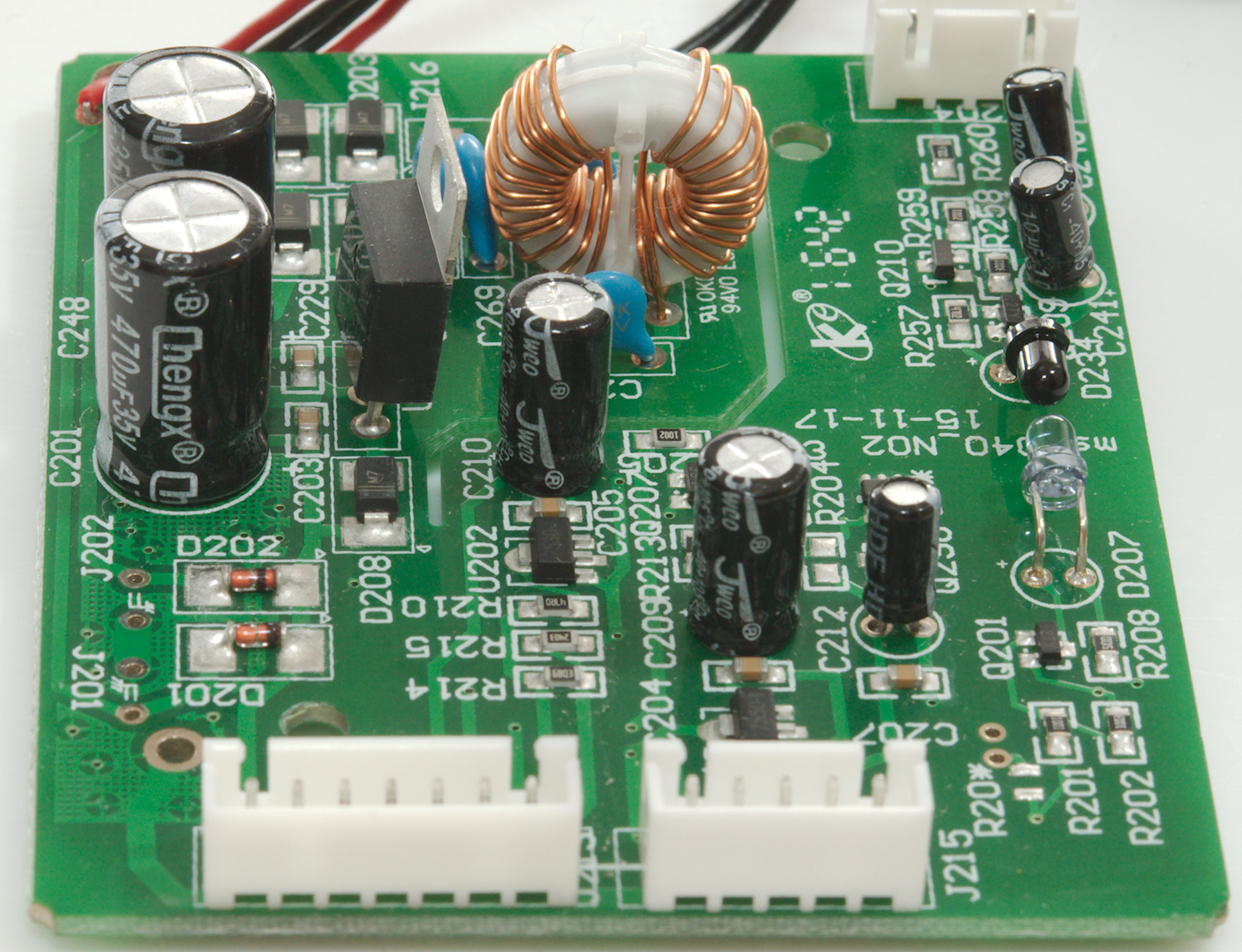
The power supply has a common mode coil followed by a bridge rectifier (D203, D204, D205, D206), then smoothing caps (C201, C248) and finally a 12V regulator (U213). After this the voltages from mains, 9V and 6xAA batteries are gated together with some diodes (D201, D202, D208) and goes to the meter circuit.
There is also two voltage regulator circuits one 3V (U202: 7530-1) and one 5V (U201: 7550-1), both supplied from the meter circuit. In this block is also a 1.25V reference (U3: LTQA->LT1790).
The last part of this circuit board is the RS232 interface, it is a led transmitter (D207) and led receiver (D234). The receiver is not powered and must draw its power from the RS232 connection.


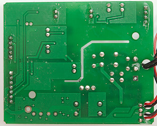
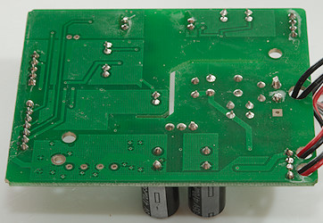
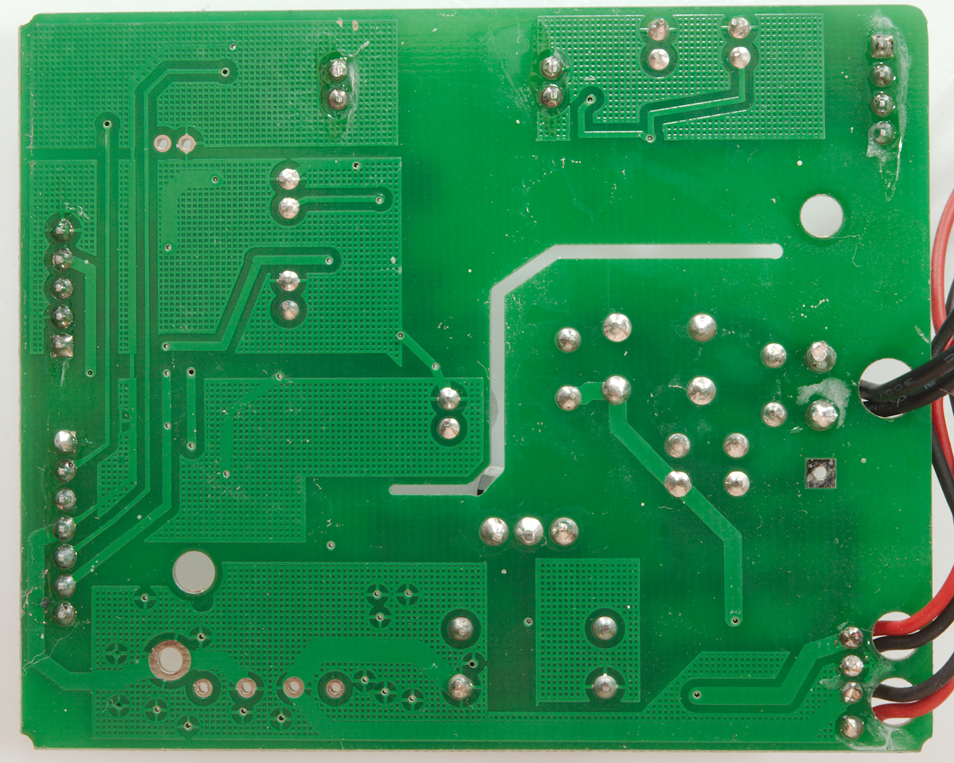
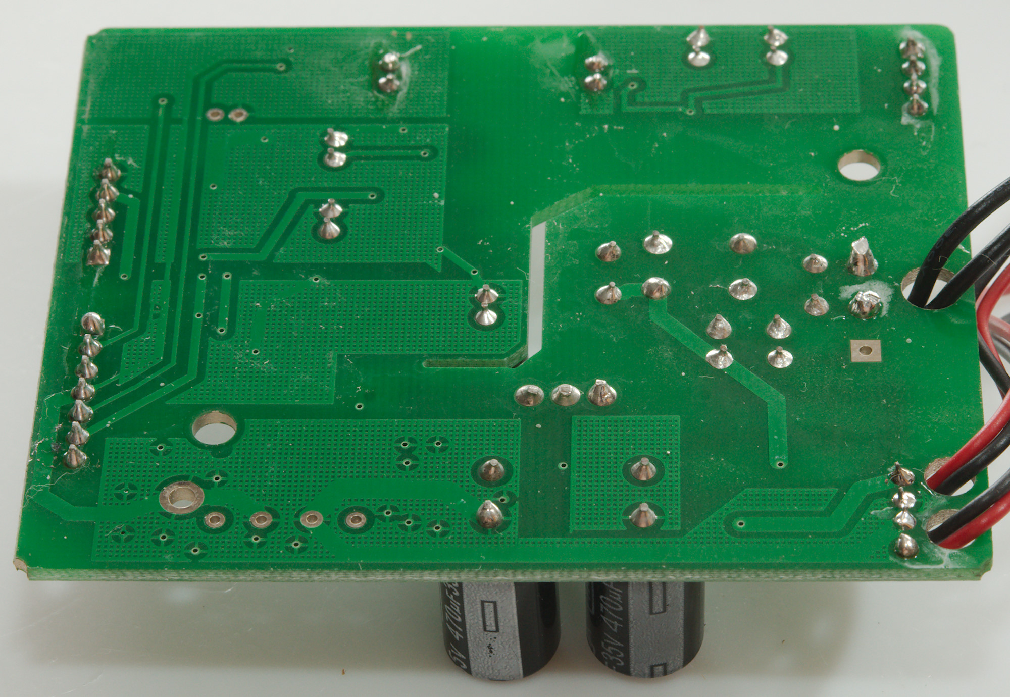
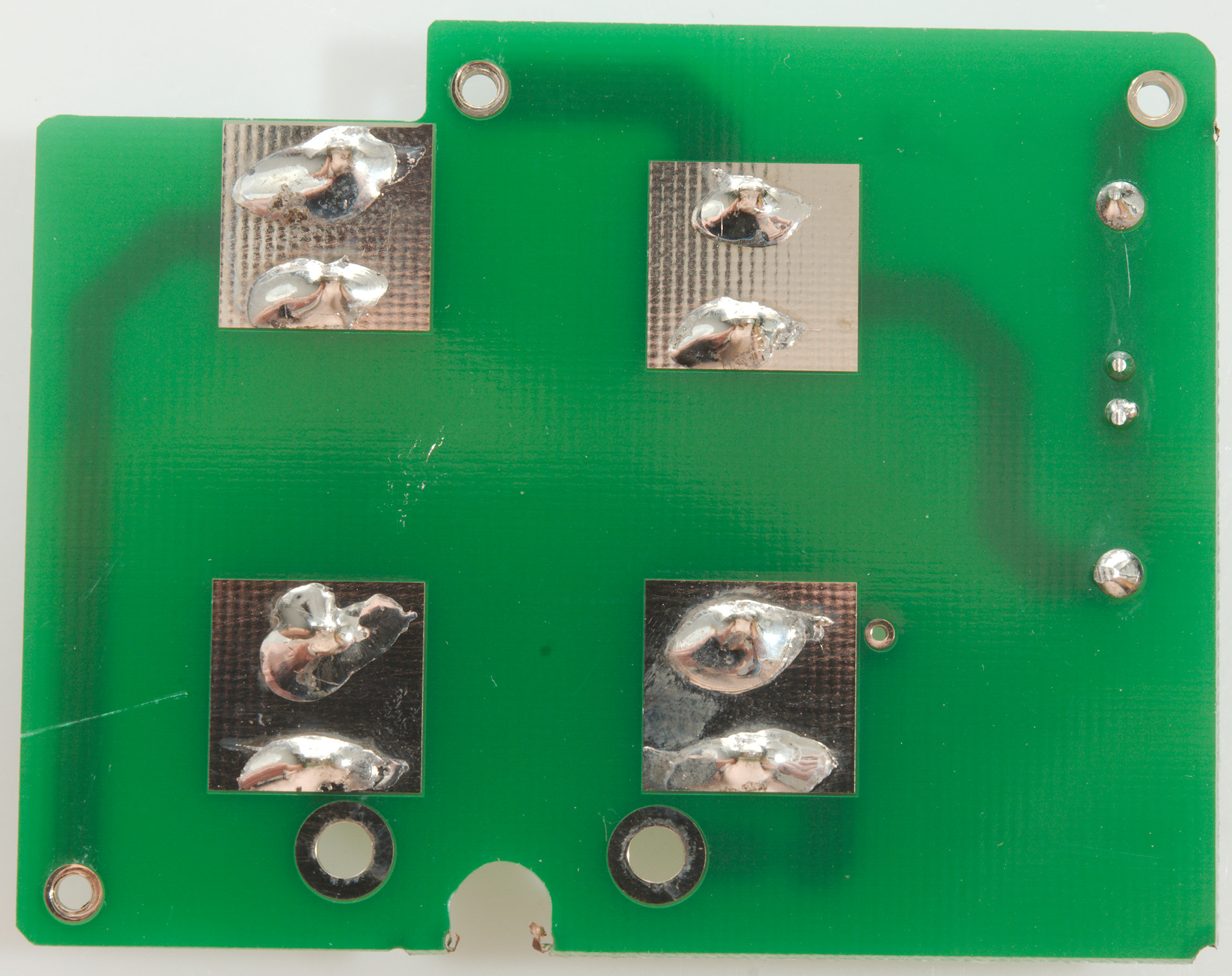
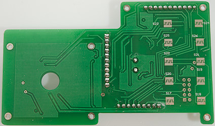
There is nothing on this side of the board.
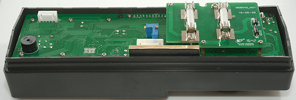
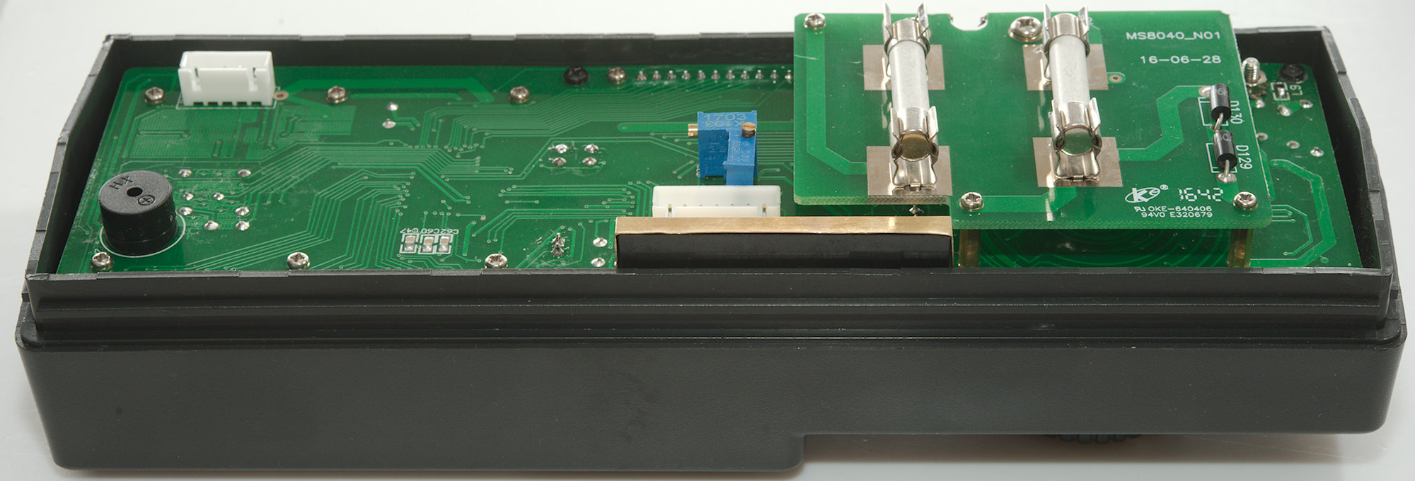
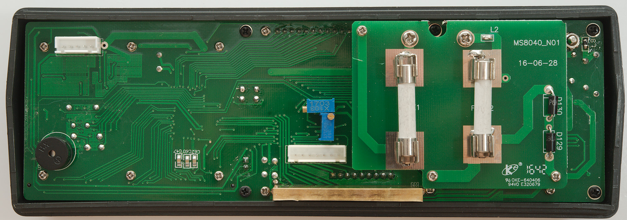
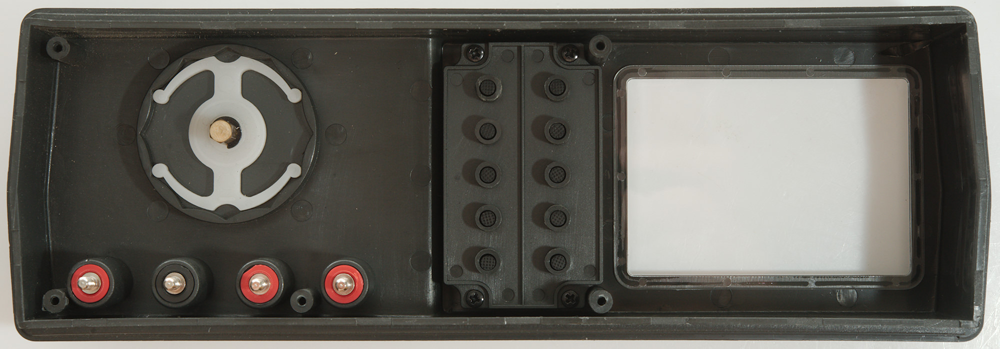
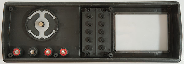
Most of the meter is in the front panel.
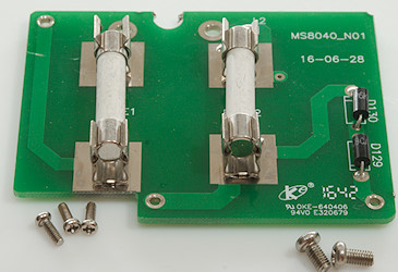
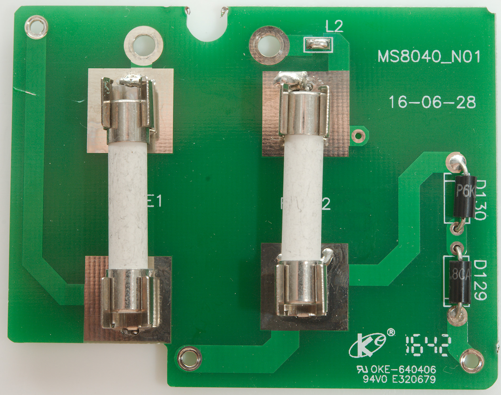
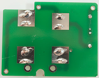
The fuse board is mounted with two larger screws that is connected to the current terminals on the front and 3 smaller screws.

The two diodes is 7V TVS diodes that is used to clamp voltage across the uAmA sense resistors (Fuse 2 is uAmA).
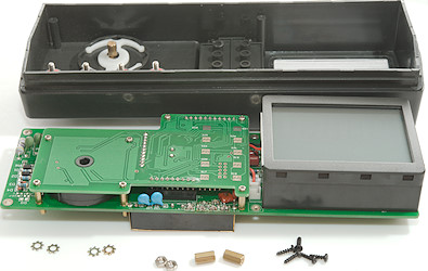
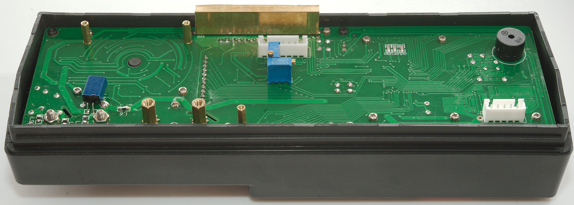
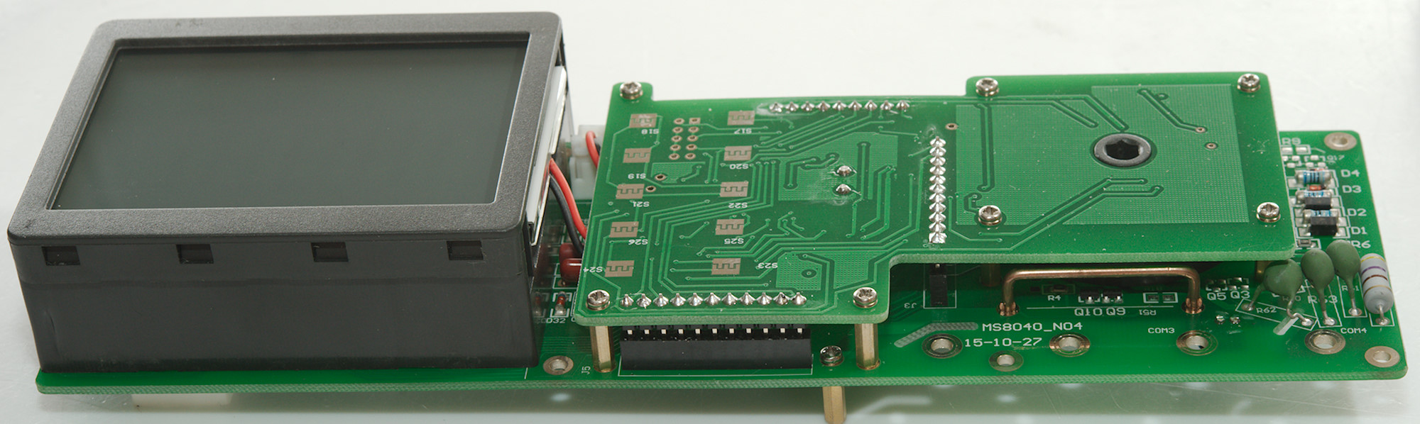
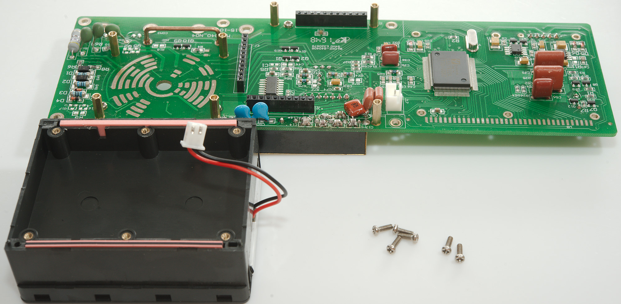
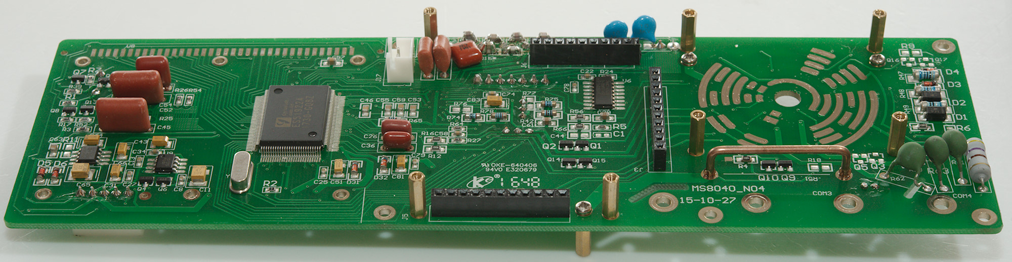
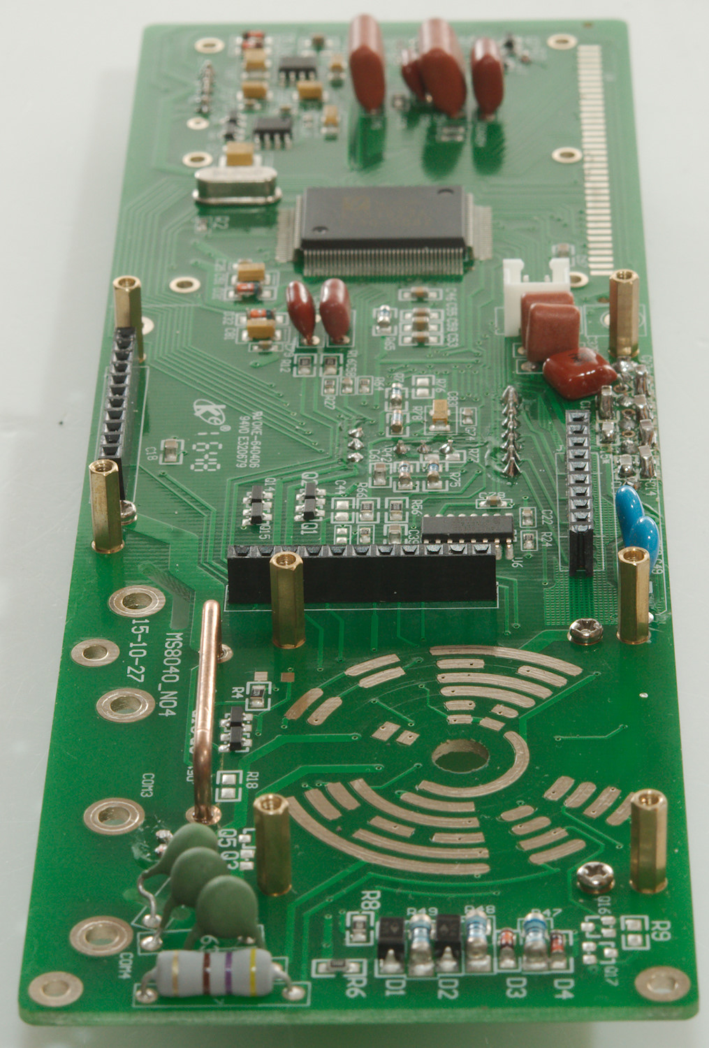
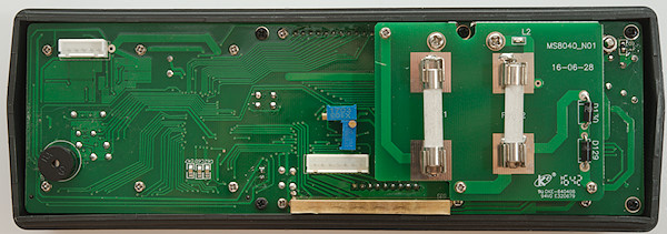
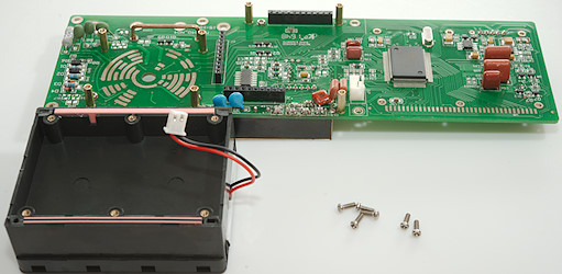
I had to remove 4 nuts for the input terminals and 5 black screws before I could remove the multimeter electronic.
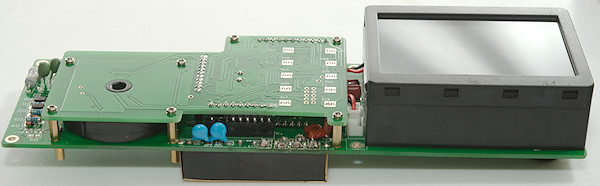

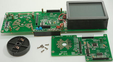
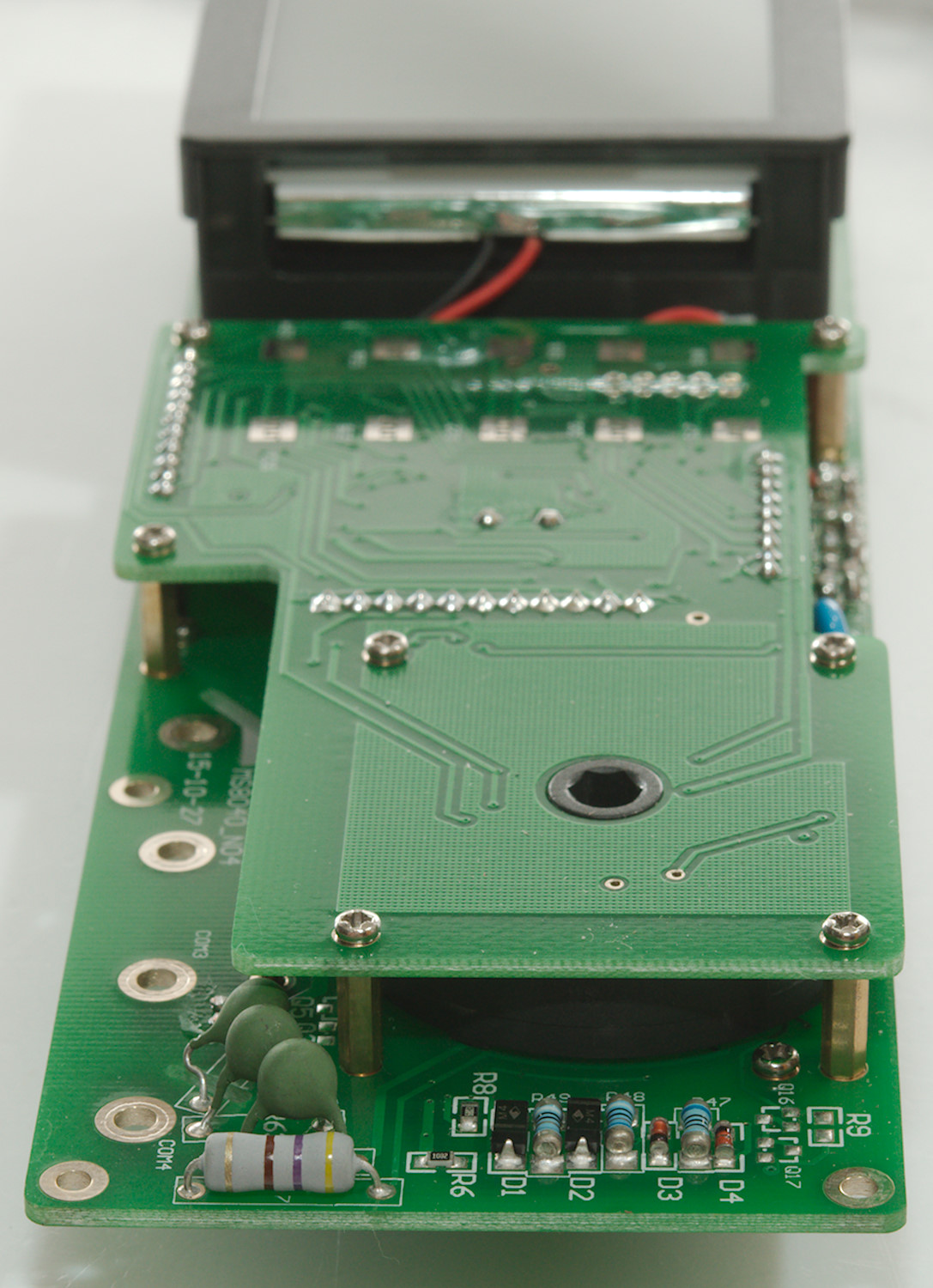
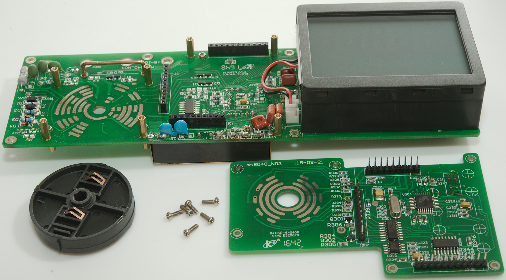
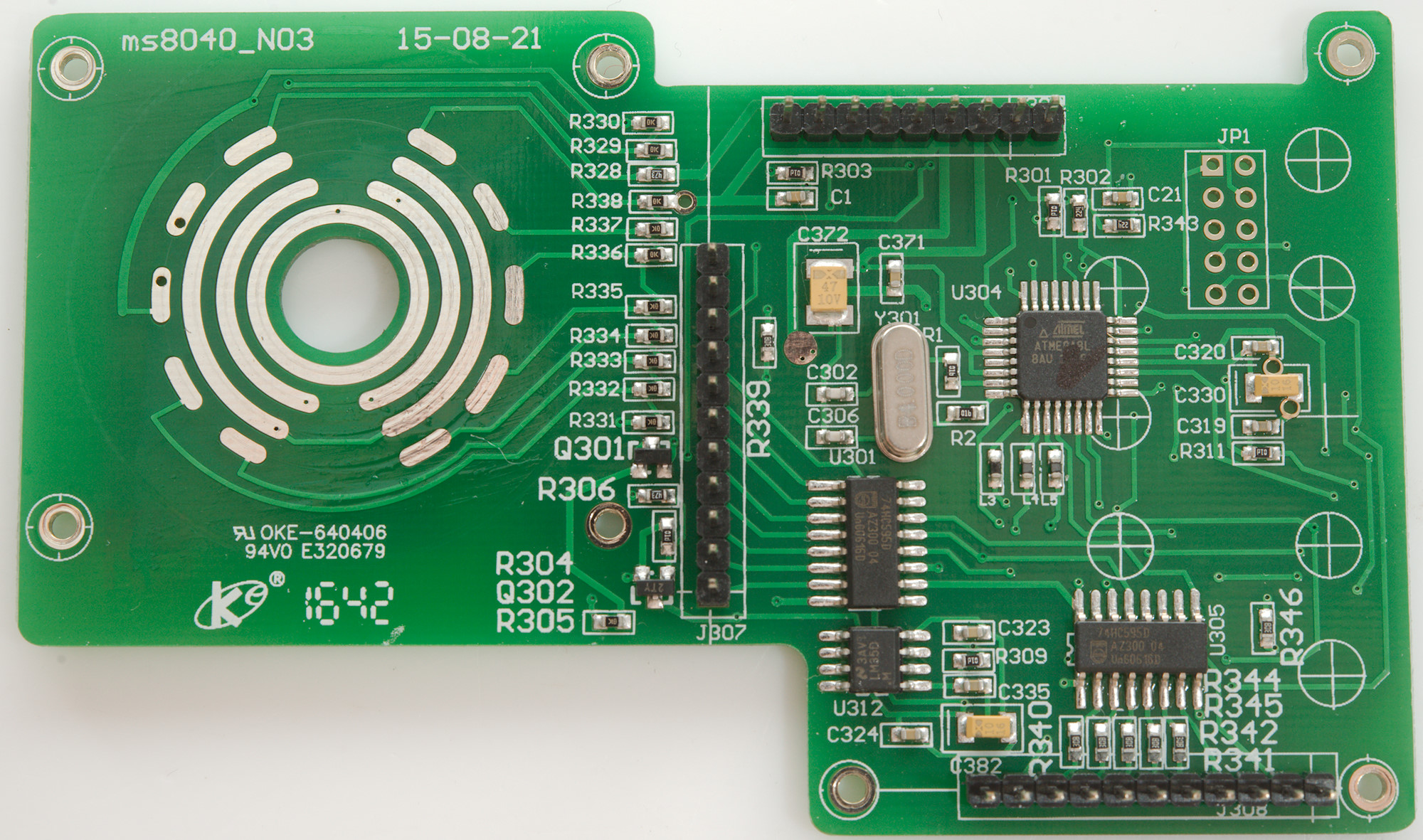
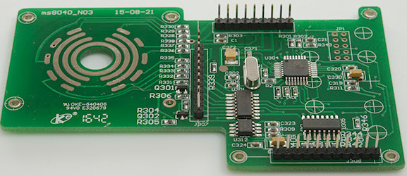
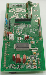
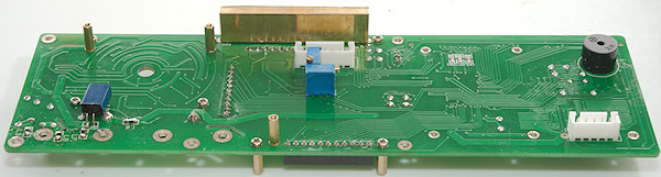
6 more screws and the two circuit board could be separated
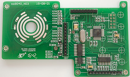
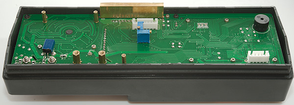
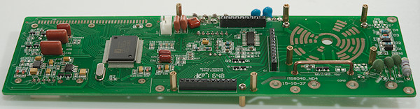
This circuit board has a microprocessor (U304: ATMEGA8L) and two shift registers (U301, U305: 74HC595) probably as output extenders. My guess is that it do some adaption of the range switch codes.
There is also a thermosensor (U312: LM35D), this is probably used as cold junction compensation in the thermocoupler mode.
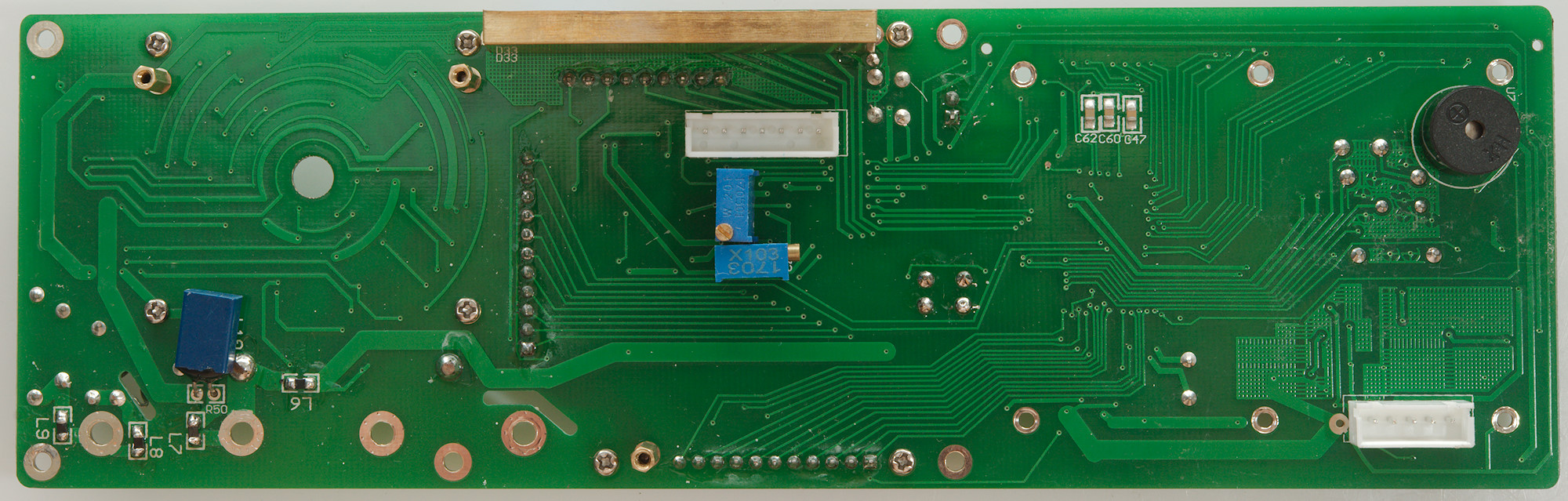
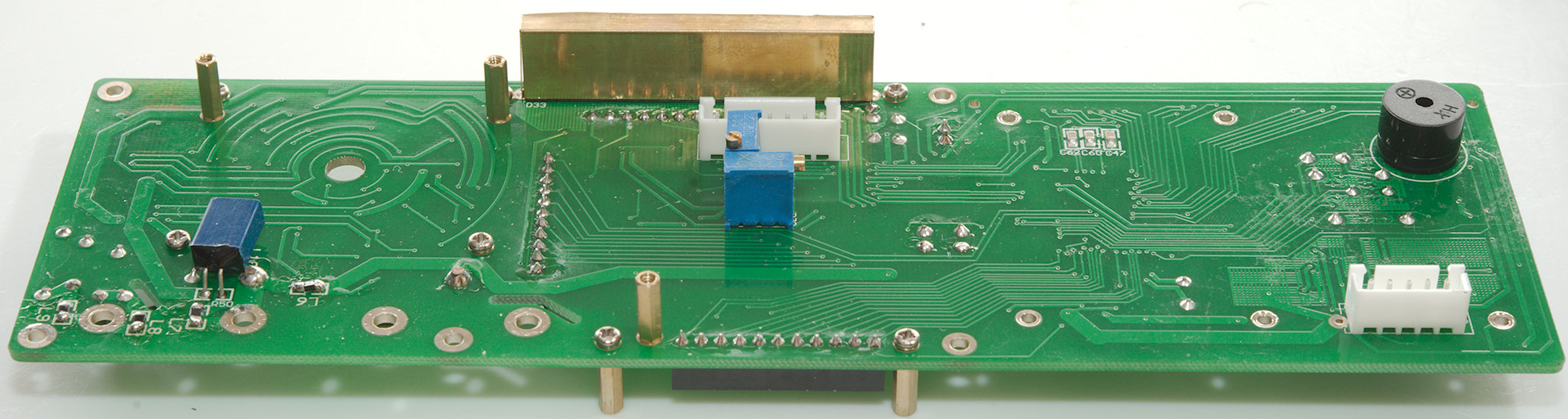
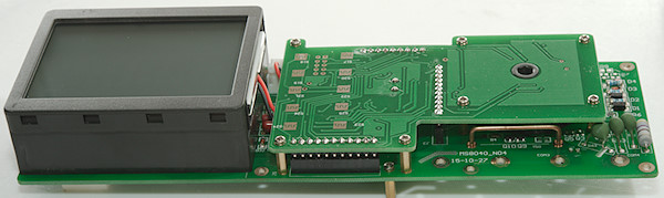
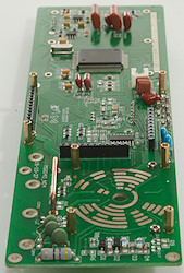
I had to remove 6 more screws to remove the display.
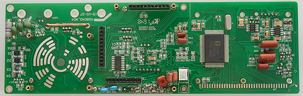
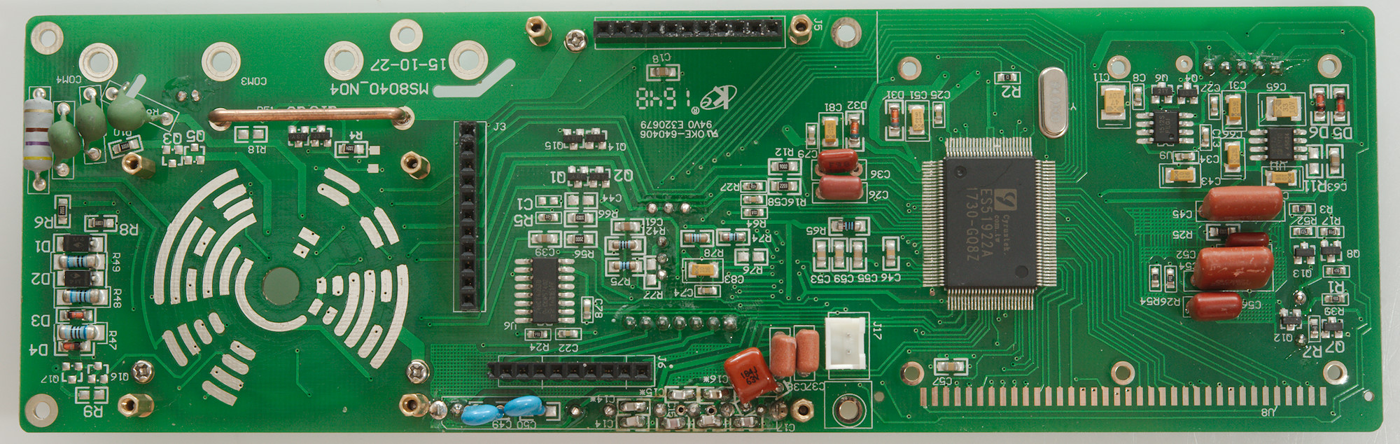
The current sense circuit on this meter is a bit special, it uses 3 resistors (R49: 9ohm, R48: 90ohm, R47: 900ohm) with bypass diodes on R49 (R1 & D2) and R47 (D3 & D4), this circuit gives a fairly high burden voltage.
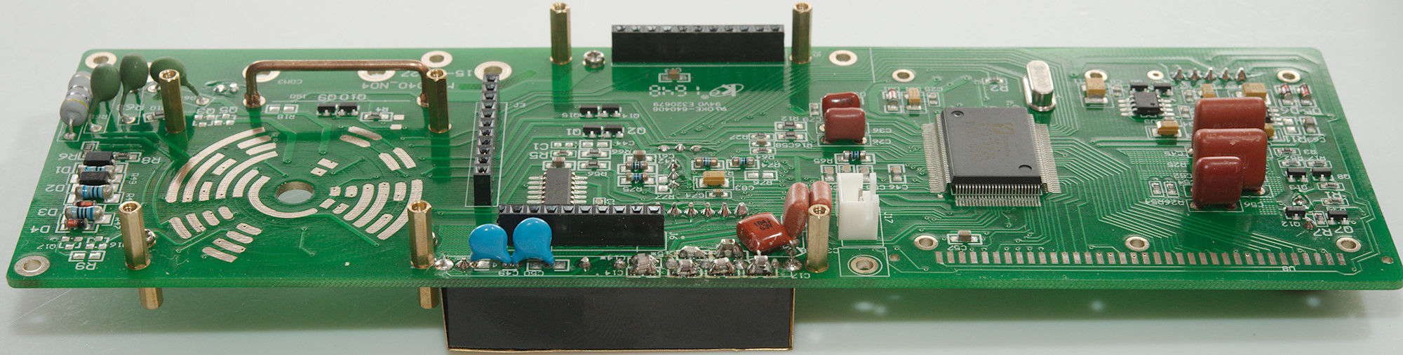
The voltage input has 3 PTC's and a 460ohm resistor for 4 input paths. There is 3 transistor pairs (Q1 & Q2, Q9 & Q10, Q14 & Q15) for protection in ohms and other sensitive ranges.
The range switch and the multimeter chip (ES51922A) handles most of the switching, but there is a single mux (U6: 4053). The two chips (U9 & U11:AD707J) is probably the RMS converter.
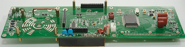
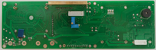
The golden box is the voltage input resistor and reference resistors, there is capacitors on the back to give a fairly good frequency response.
Conclusion
As usual on cheap meters the CAT rating is too high, with fuses rated 250V it cannot be a 1000V meter, but for a bench meter this is usual not very important.
The meter has good precision and lot of functions, but there is a few bugs (min/max do not reset) and some functions that do not belong on a bench meter (Auto turn-off of backlight and meter). The display is very good when the backlight is on, but it can be problematic to get enough light into it with backlight off and be careful not to blow the fuses, to replace them the meter must be taken apart. The computer software is not very useful with missing save functionality.
This meter is closer related to handheld meters than to professional bench meters, this do not make it a bad meter, just a bit limited compared to more expensive bench meters.
Notes
If I where going to use this meter I would hack the backlight to turn it permanently on (maybe at a slightly lower brightness).
How do I review a DMM
More DMM reviews