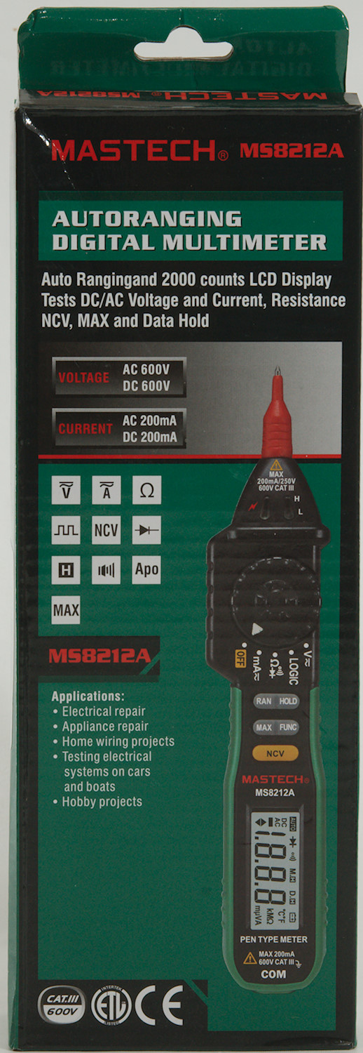
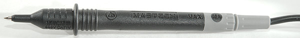
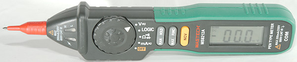
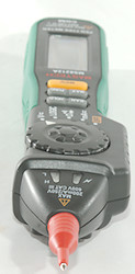
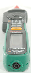
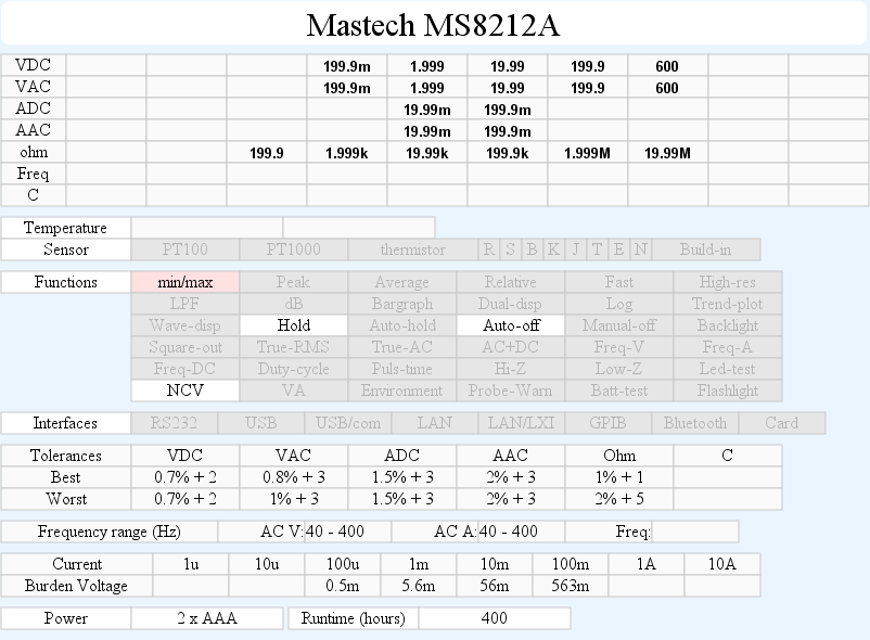
DMM Mastech MS8212A
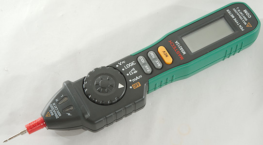
This is a pen style DMM with voltage, ohms and current.
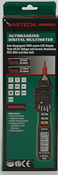
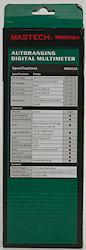
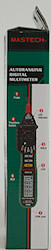
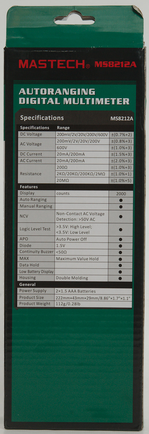
The meter arrived in a typically Mastech box with an image of the meter and specifications on the box.
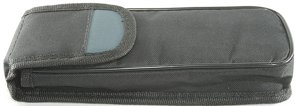
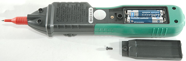
Inside the box was a pouch and a manual.
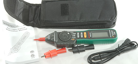
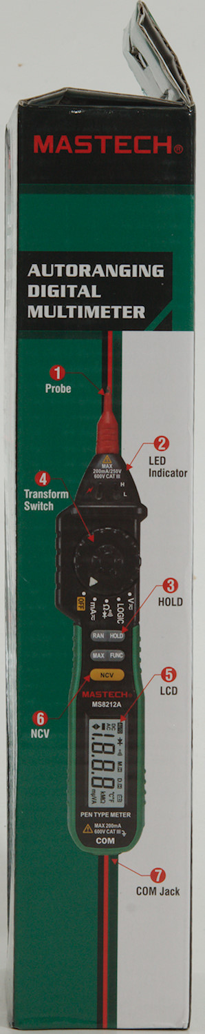
In the pouch was the meter and a single probe, together with alligator clips.
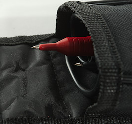
Because the probe are without any tip protection and the meter is a bit long for the pouch, the probe tip can fairly easily poke through the pouch.
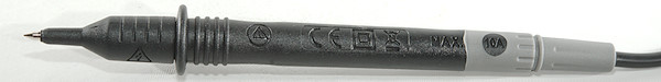
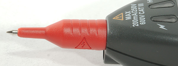
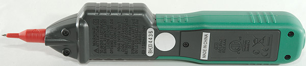
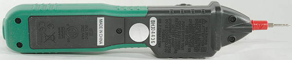
The probe are branded Mastech and rated for 10A and up to 1000V
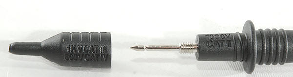
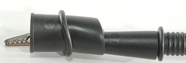
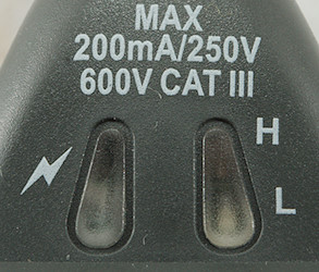
The tip cover must be on for CAT III or CAT IV rating. This tip cover is screw on/off.
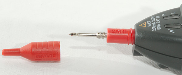
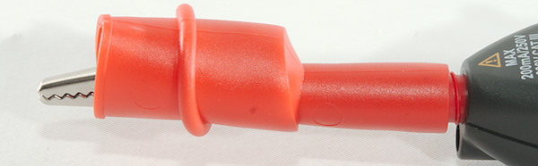
The meter also has a tip cover, but here the rating is limited to CAT II/III and 600V to match the meter.
This tip cover is screw on/off.
Both meter and probe can be equipped with alligator clips, these are screw on types.
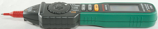
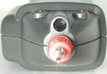
The front has a hole for a led, but it is not mounted on this model.
Display
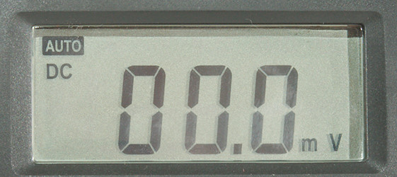
Typical display during usage, it will show the number and what measurement is selected.
At the front are 3 leds, a red/green set for H/L display in LOGIC mode and a red one for NCV detection.
Functions
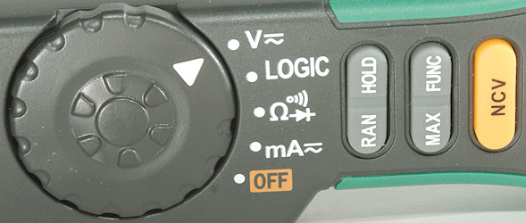
Buttons:
- RAN: Press to select manual range, press again to change range, hold down to return to automatic range. This button must be used for AC mV.
- Hold: Freezes the display reading.
- Max: Shows maximum value, this meter can only show maximum, not minimum.
- Func: Select between AC and DC, ohm, diode and continuity. In LOGIC it must be held down to activate leds.
- NCV: Non contact voltage, this do not affect selected mode/range, but enables the NCV function. A single led and the buzzer is used as indicator.
Rotary switch:
- Off: Meter is off
- mA: mA range for DC and AC
 : Resistance, diode and continuity.
- LOGIC: 20V range, pressing the "FUNC" button will turn red/green leds on depending on voltage.
- V: Voltage DC and AC, use FUNC to select AC and for mV AC the RAN button must be used.
Input
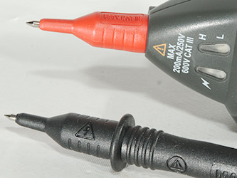
One probe is integrated in the meter, the other is a loose test wire. As usual it is a bit problematic to share current and voltage on the same input.
Measurements
- Volt and frequency
- 1 VAC is 5% down at 2kHz
- Max function can capture pulses of about 200ms
- mV AC can only be selected manually
- Input impedance is 5 to 5.26Mohm on DC and AC
- mV DC range is 10Mohm input impedance up to about 1.8V, then it drops to 5Mohm
- The specifications says it is protected to 250V AC/DC on mV range and 600V DC/AC on V range
- Logic level requires holding the Func button down to activate the leds, it can easily show 1ms pulses both high and low, 0.1ms can also be seen.
- Logic level show green led below 1.47V including negative voltage and show red led above 3.5V. This do not work with 3.3V logic.
- Logic level input impedance is 1.7Mohm
- Current
- Current is protected by a 0.25A/250V 5x20mm fuse
- Ohm, Continuity, diode and capacitance
- Ohm needs about 3.7s to measure 100ohm
- Ohm is 0.44V open and 0.2mA shorted
- Continuity is moderate speed (About 120ms) and not very loud.
- Continuity beeps when resistance is below 50ohm
- Continuity is 0.44V open and 0.2mA shorted
- Diode range uses 1.6V, max. display is 0.999V at 0.23mA, max. current is 0.65mA shorted
- The specifications says it is protected to 250V DC/AC
- Miscellaneous
- Current consumption of meter is 2mA in DC mode and 2.6mA in AC mode, the Logic leds increases current to 6.5mA
- Meter works down to 1.4V where it fails, battery symbol show at 2.3V.
- Reading is stable down to about 2V, then readings goes down
- The meter usual need a few display update to reach the final value.
- Viewing angle is good, except from the top.
- Display updates around 2.5 times/sec
- Will automatic turn power off in about 15 minutes.
- Weight is 130g with batteries, but without probe or other accessories.
- Size is 222 x 44 x 29mm.
- Probes
- Probe resistance 21mOhm for one.
- Probe wire is fairly soft and 82cm long.
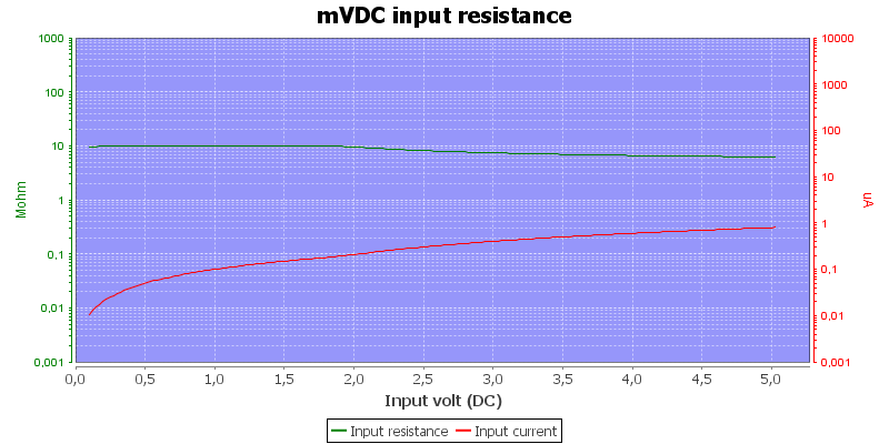
Input impedance in mV DC range.
High DC voltages in AC ranges can confuse the meter.
The meter can only show max, not min.
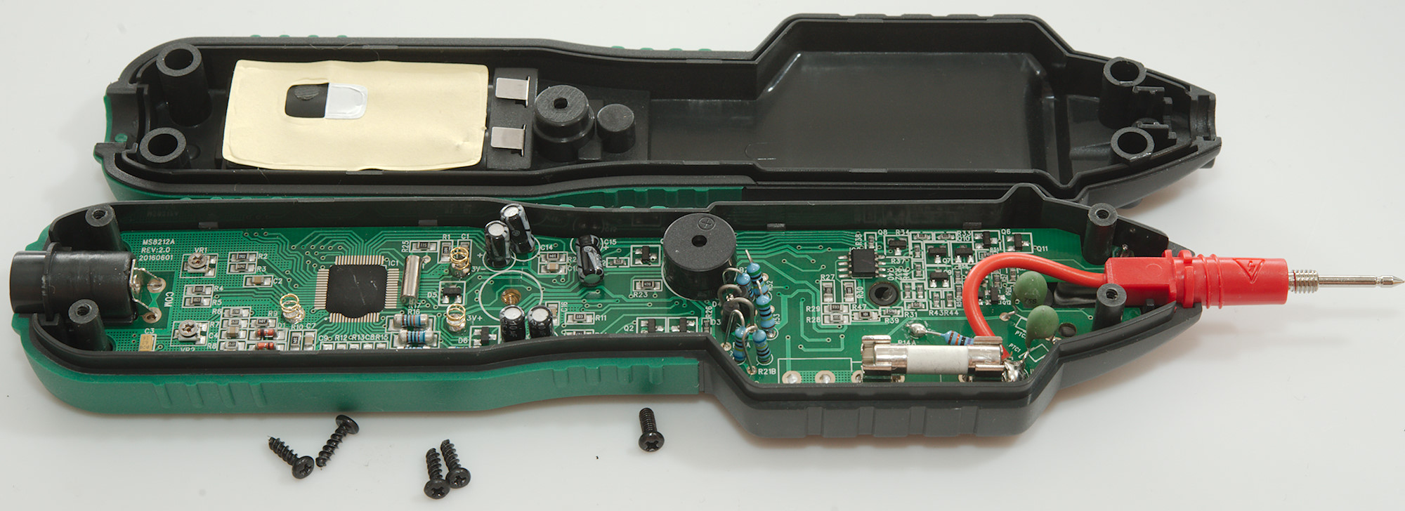
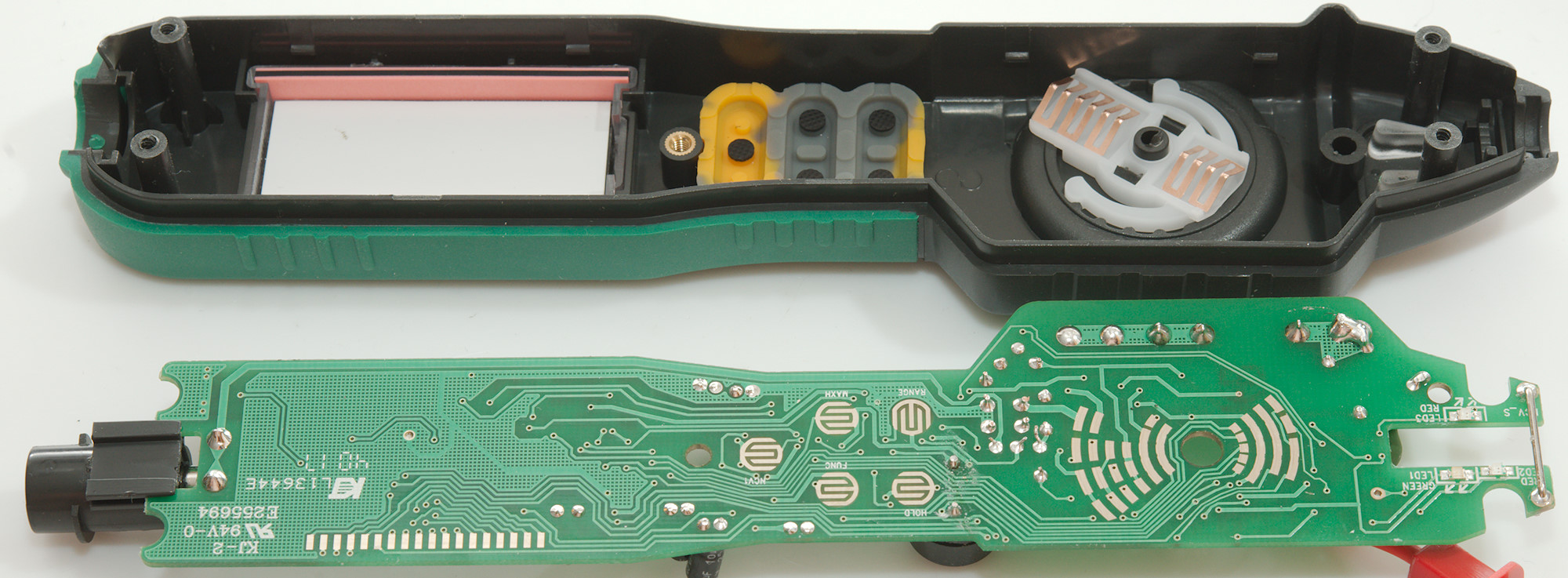
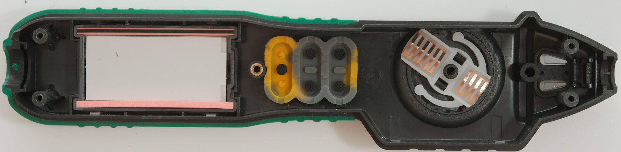
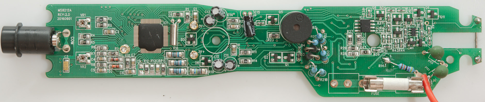
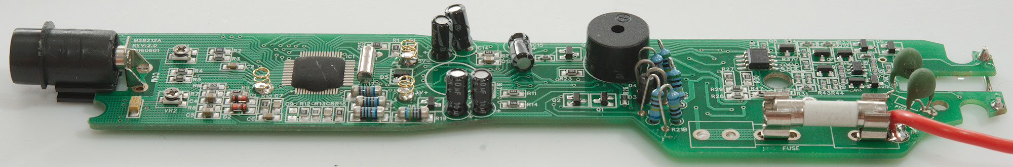
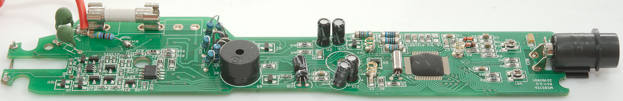
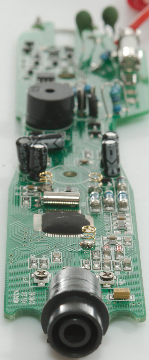
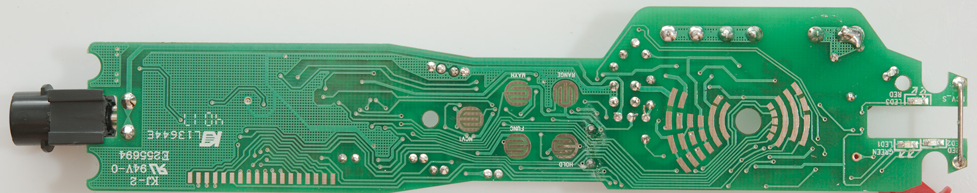
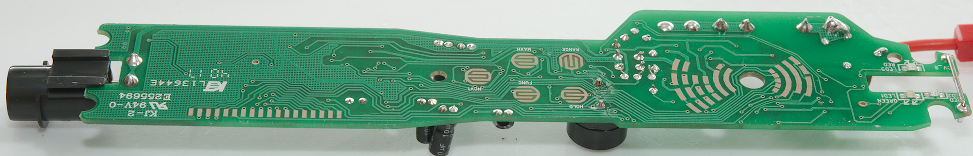
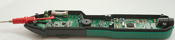
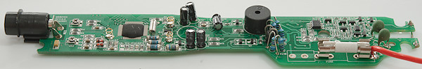
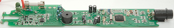
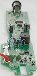
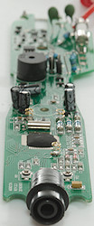
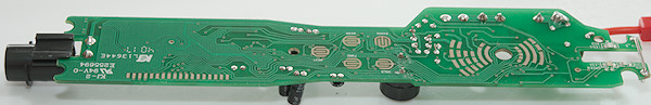
Tear down
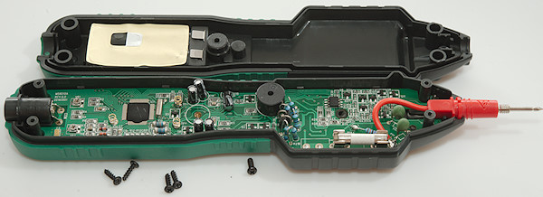
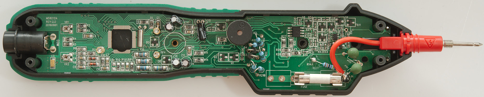
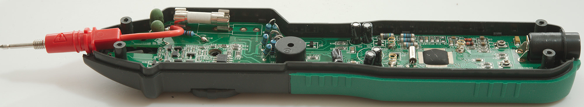
I had to remove 5 screws to open the meter, four where self tappers the last had a real thread.

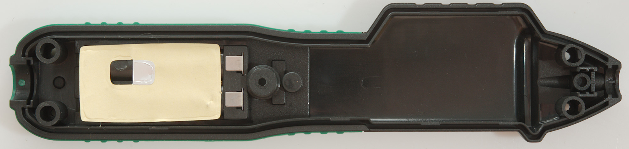
The circuit board is made to fit the box exactly and is mounted with clips.

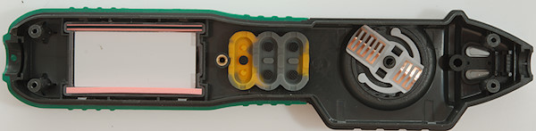

The current sense input use a 250mA fuse and then a shunt resistor (R20: 1ohm) with two diodes across (D3 & D4). The ohm input has two PTC's (PTC1 & PTC2) in series and two transistors (Q1 & Q2) to clamp any voltage. The voltage input has two 10Mohm paths (R52, R53 & R21A, R21: 4x5Mohm). One of the paths are just a load on the input (R52 & R53). The other parts near the input is the LOGIC handling (IC1: LM358, OpAmp), the sense for that goes through a resistor (R14A: 470kOhm), there is also a couple of transistor to drive the leds. The NCV must be the other transistors and the chip (U4: marked 22T4).
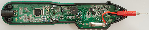
At the other end of the meter is the multimeter chip (IC1) and two trimpots (VR1 & VR2)
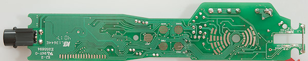
This side has the pads for switches, range switch and lcd, there is also the 3 leds and the NCV antenna.
Conclusion
With a 250V fuse the meter do not live up to a 600V CAT rating, but safety looks acceptable for occasion home mains work.
The meter is a bit low on ranges with no capacitance, frequency or uA, but the calibration on the meter is very good on all ranges. The logic function is for 5V logic and cannot catch fast pulses.
Notes
This meter may exist with many different names on it and small variations in functions.
How do I review a DMM
More DMM reviews