DMM Mastech MS8216
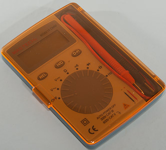
This is a small pocket DMM with voltage, frequency, ohms and capacitance.
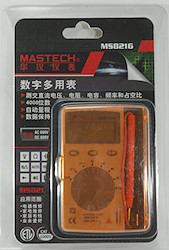
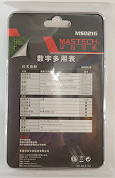
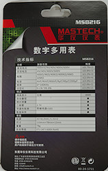
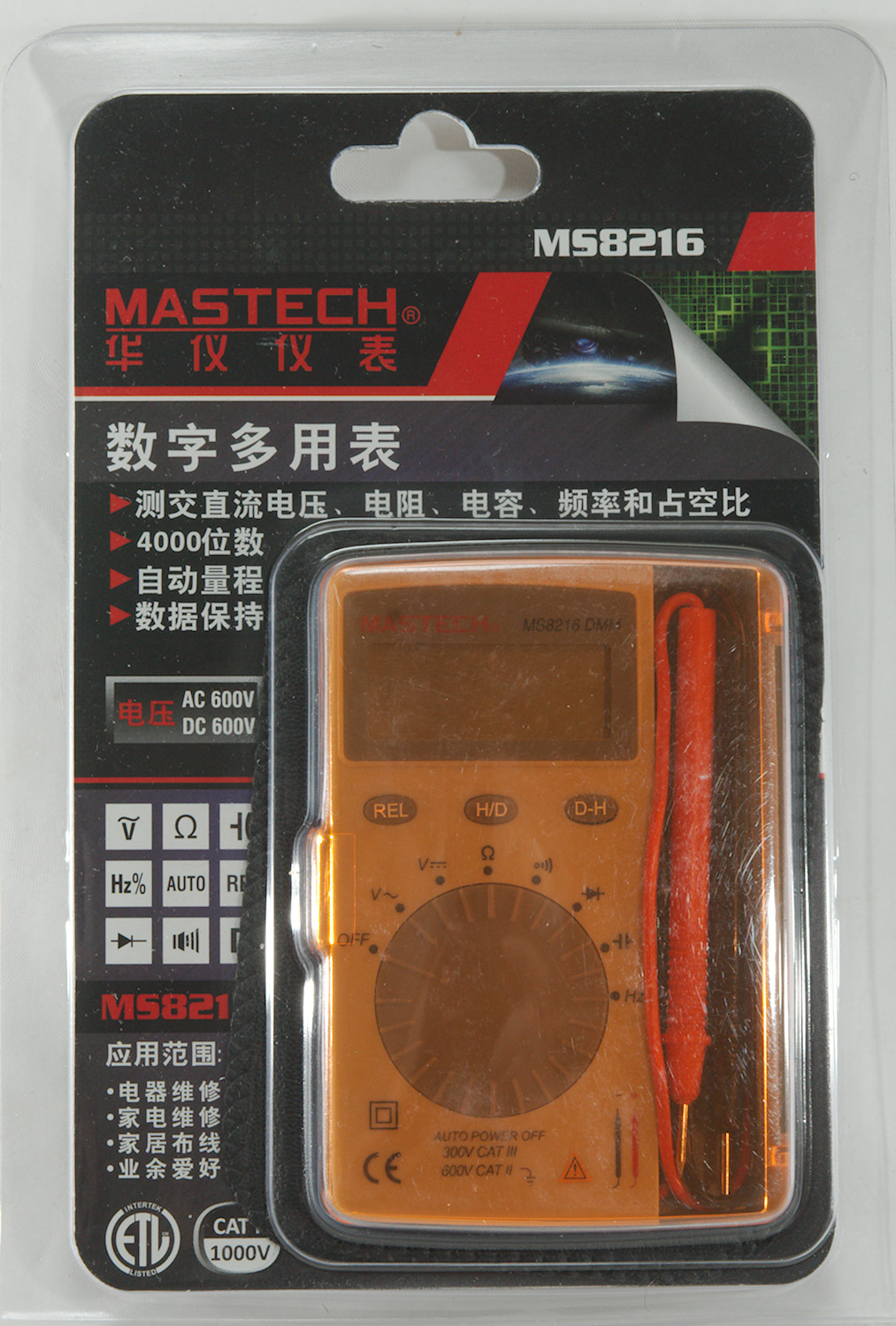
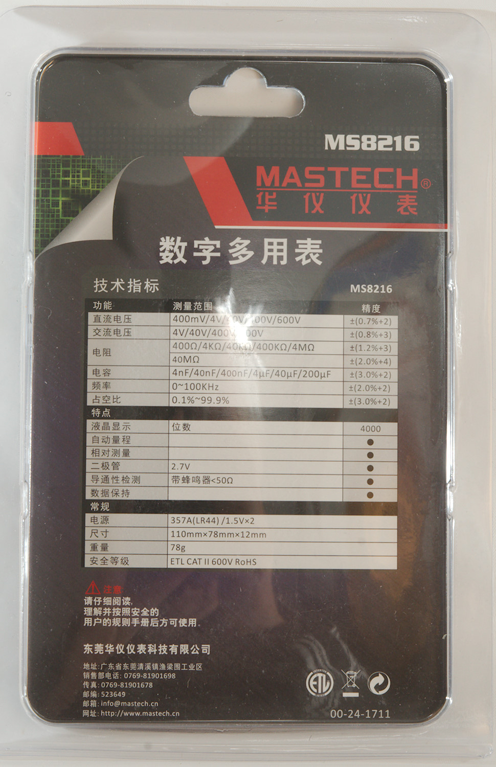
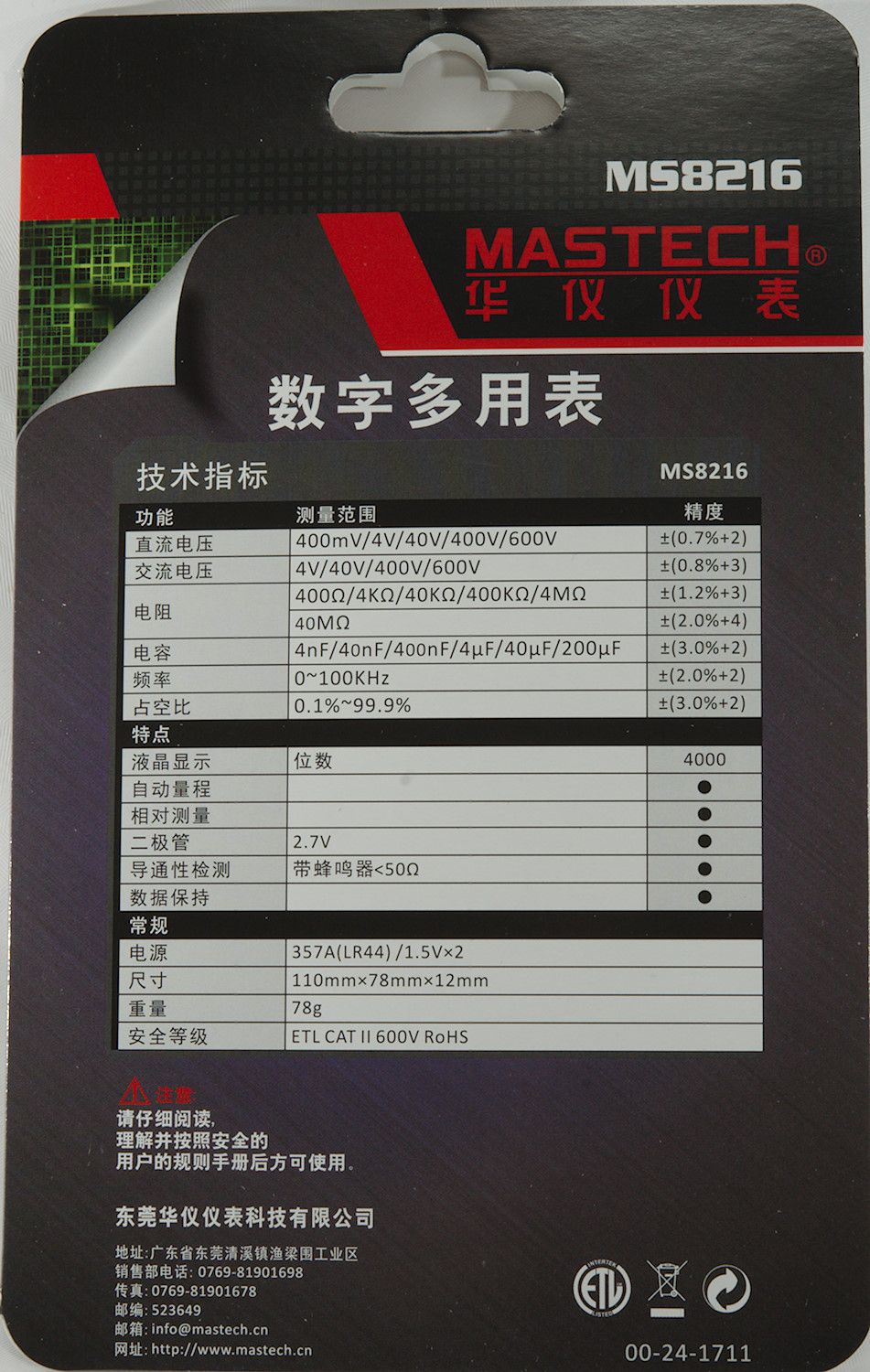
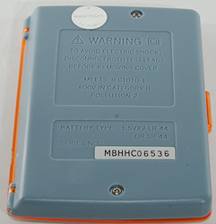
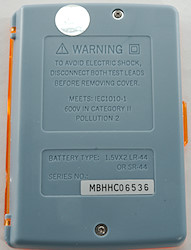
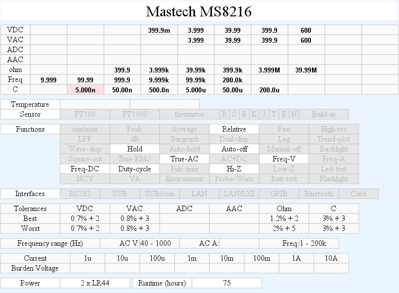
The meter was in a clamshell pack. On the back is a the specifications.
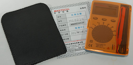
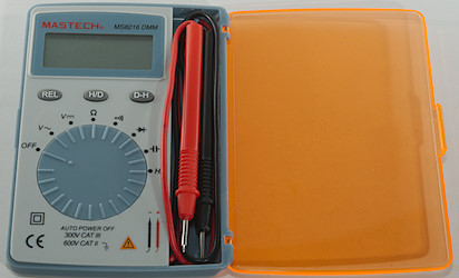
In the pack was the meter and a manual in English.


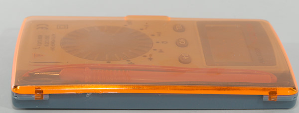
The probes are small and they are not round, but ellipse shaped.
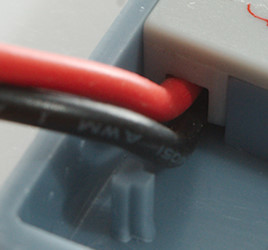
The probes are directly connected to the meter, no plugs and sockets.
The range switch is easy to turn, but the detents are not very strong and it is very easy to place the switch between ranges.
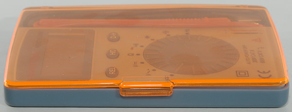
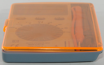
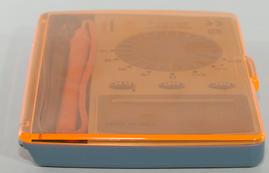
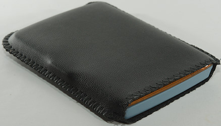
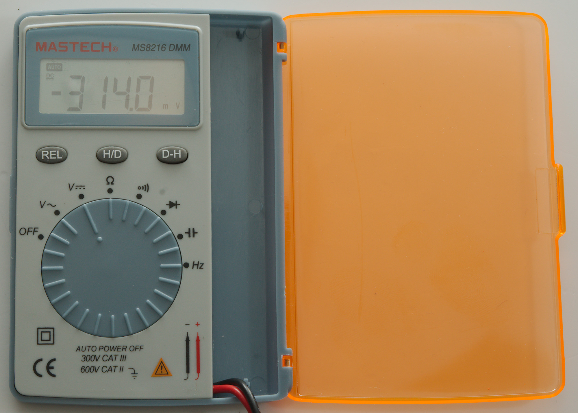
A pouch is included.
Two screws must be removed to get battery access.
Display
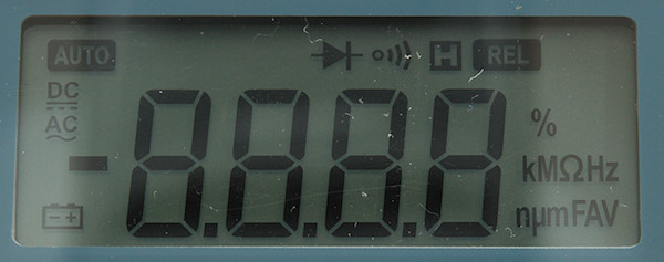
The above picture shows all the segments on the display.
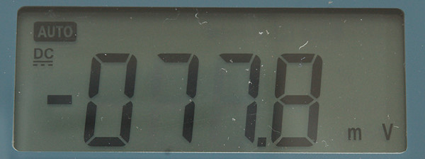
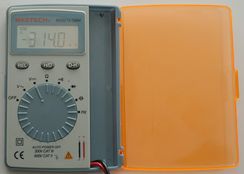
Typical display during usage, it will show the selected range and value.
Functions
Buttons:
- Rel: Store current display value and show all new values relative to this value.
- H/D: This is short for Hz/duty cycle and will show frequency and duty cycle in both DC, AC and frequency mode.
- D-H: This is the hold button and will freeze the display reading, until pressed again.
Selection of Rel and Hz/duty will disable auto ranging and it stays disabled
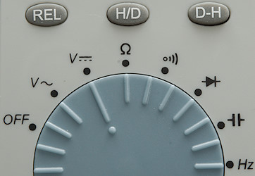
Rotary switch:
- Off: Meter is turned off
- VAC: Voltage AC, frequency and duty cycle.
- VDC: Voltage DC, frequency and duty cycle.
 : Ohm.
 : Continuity.
 : Diode.
 : Capacitance.
- Hz: Logical frequency input.
Input
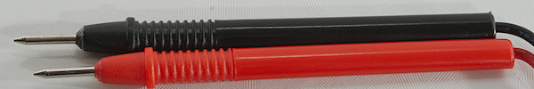
This meter only have a red and black probe coming out, no other connections.
Measurements
- Volt and frequency
- At 1V rms input on frequency the counter range is from 2Hz to 50kHz
- At 2V rms input on frequency the counter range is from 0.6Hz to 100kHz
- At 5V rms input on frequency the counter range is up to 290kHz
- Duty cycle works from 15% to 90% at 1kHz with 4Vpp, precision is within 3.0
- Frequency inputs do not need a zero crossing.
- 1V AC readings is 5% down at 2kHz
- Voltage input impedance is 10-11Mohm,
- mV input impedance is high below 1.5V and drops to 10Mohm above
- Frequency input is similar to mV input.
- Input protection is 600V AC/DC for voltage 250V AC/DC for frequency.
- Current
- Meter cannot measure current
- Ohm, continuity, diode and capacitance
- Ohm needs about 3.4s to measure 100ohm
- Ohm is 0.42V open and 0.17mA shorted
- Continuity is moderate in speed (100ms)
- Continuity beeps when resistance is below 55ohm
- The beeper volume is very low.
- Continuity is 0.44V open and 0.17mA shorted
- Diode range uses 1.5V, max. display is 0.999V at 0.2mA, max. current is 0.55mA shorted
- 10uF takes about 3.8 seconds to measure.
- 190uF takes about 40 seconds to measure.
- Rated overload protection is 250 VDC/VAC
- Miscellaneous
- Current consumption of meter is 0.8mA except AC where it is 1.4mA
- Meter fails below 1.4V, battery symbol show at 2.4V.
- Readings will drift about 2 count when from when battery symbols shows to the meter fails.
- Viewing angle is good, except from top
- Display updates around 2 times/sec
- Will automatic turn power off after about 15 minutes
- The meter often need many display update to reach the final value.
- Weight is 82g without accessories, but batteries.
- Size is 110 x 78 x 13mm.
- Probes
- Probe wire is a bit thin, they are 31cm long.
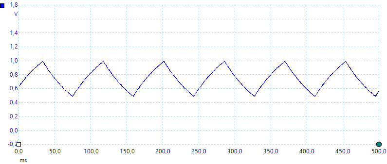
capacitance measurement waveform.
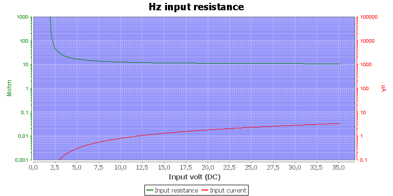
Frequency input resistance in voltage frequency position, V and mVDC is similar.
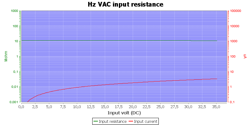
Frequency input resistance in voltage AC position.
Lowest capacitance range is sometimes out of tolerance (Up to 8%) and next time I measure the same capacitor it is inside tolerance.
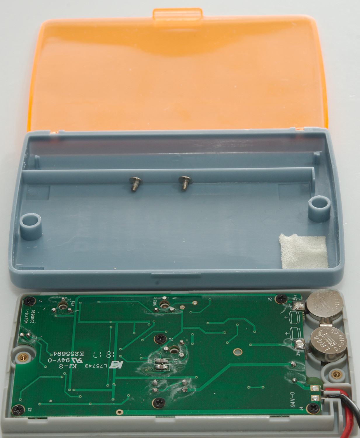
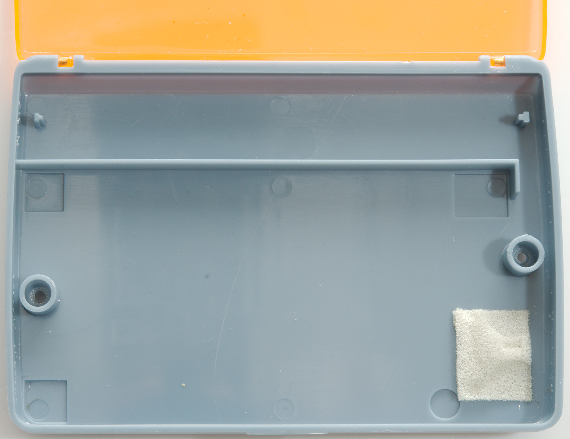
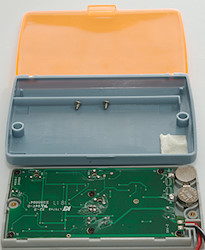
Tear down
I had to remove two screws, to open it, this is also required when replacing batteries.
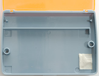
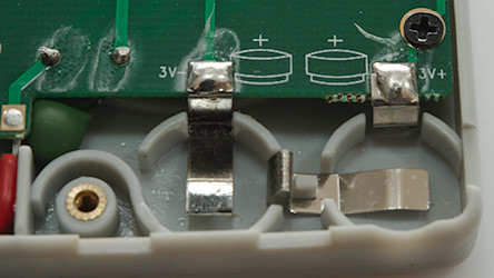
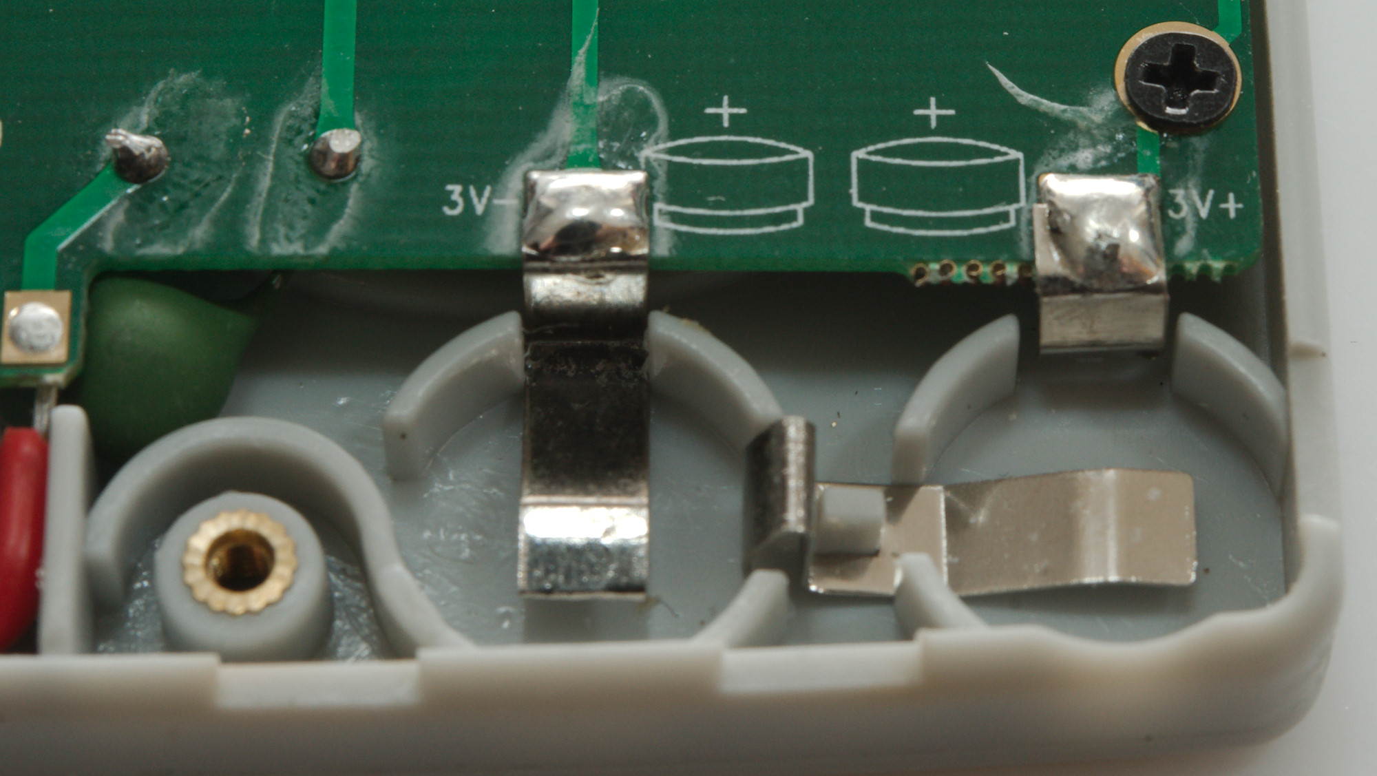
The battery holder is for two button cells.
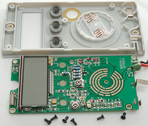
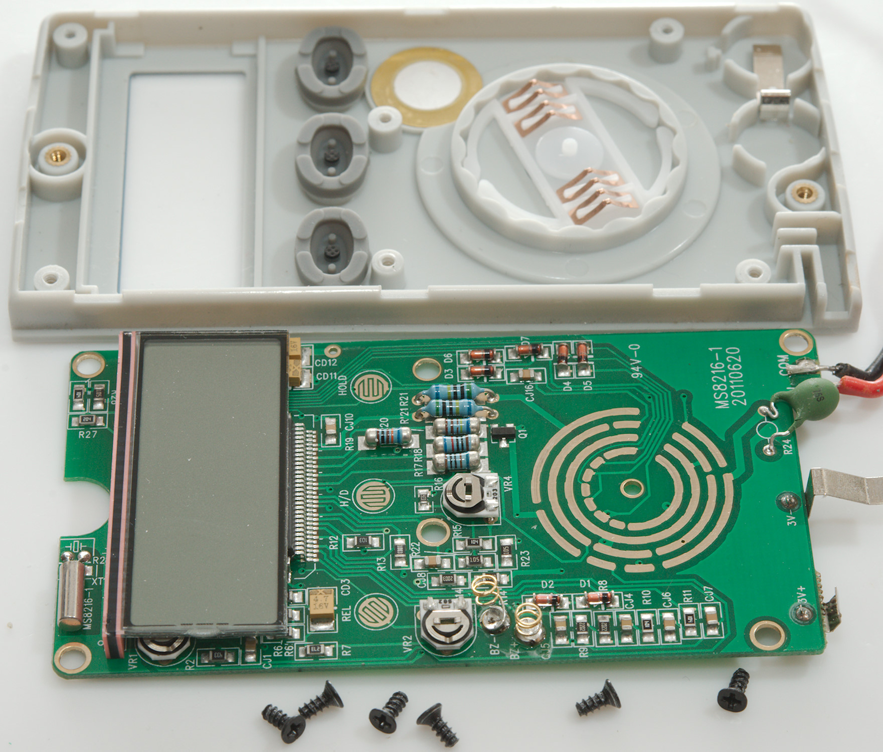
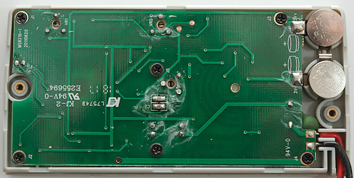
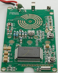
I had to remove 6 screws before I could get the circuit board out.
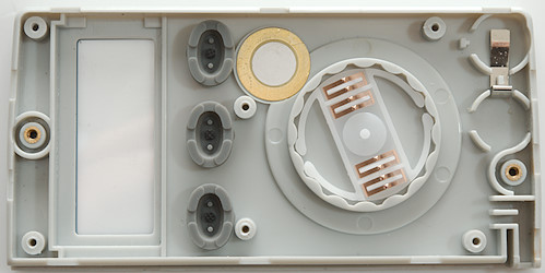
The buzzer is mounted on the front plate.
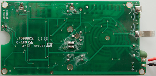
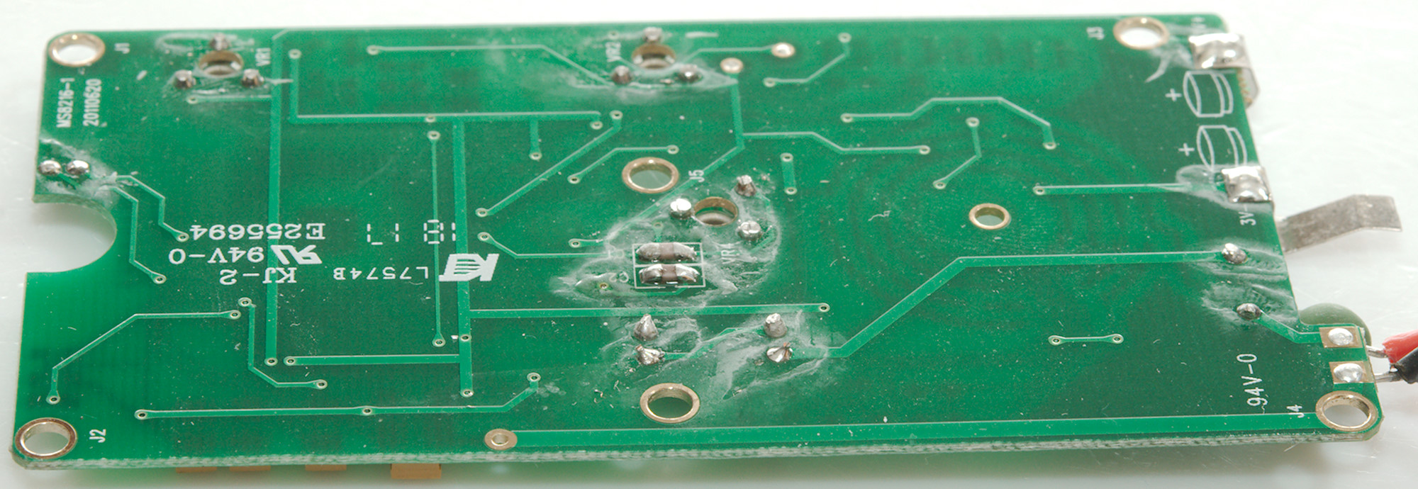
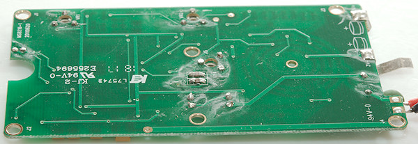
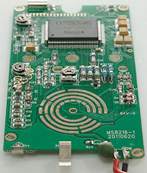
On this side there is only two capacitors and holes for adjusting the 3 trimpot (VR1, VR2, VR4).
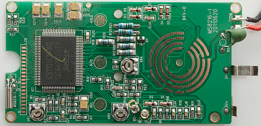
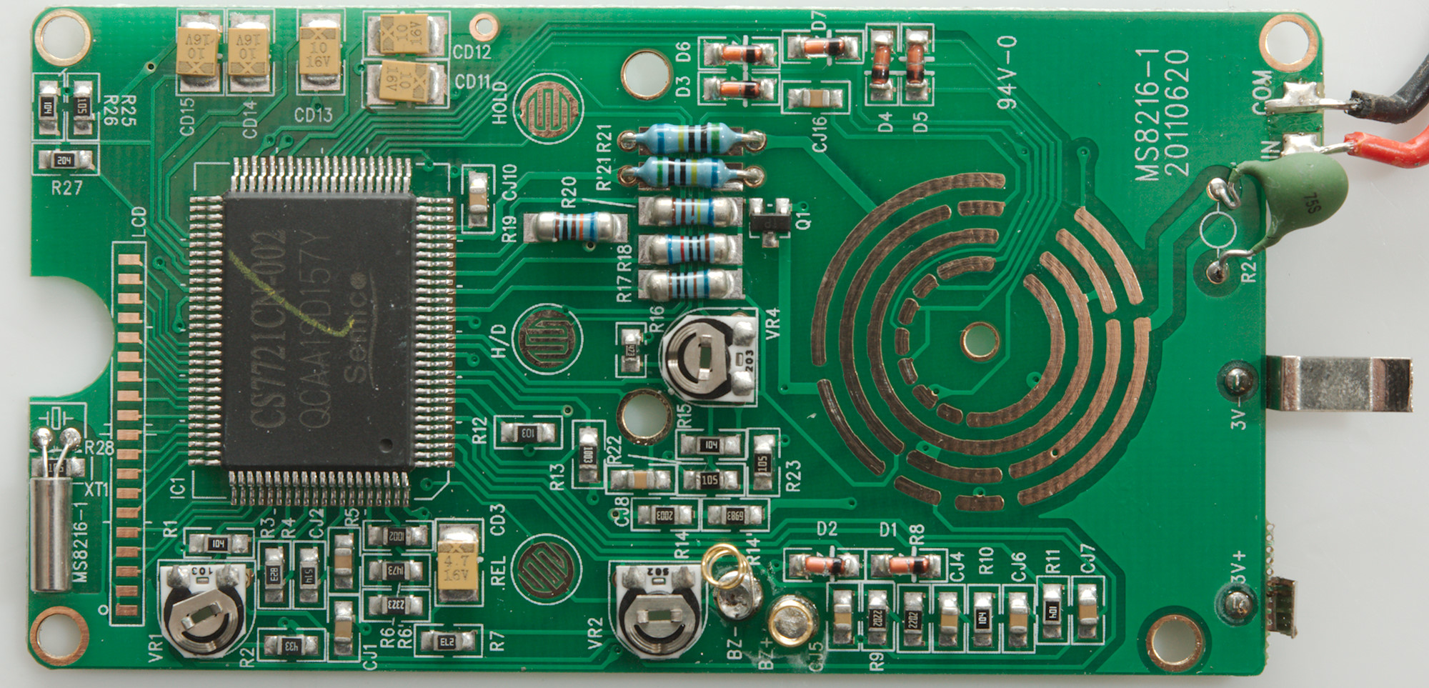
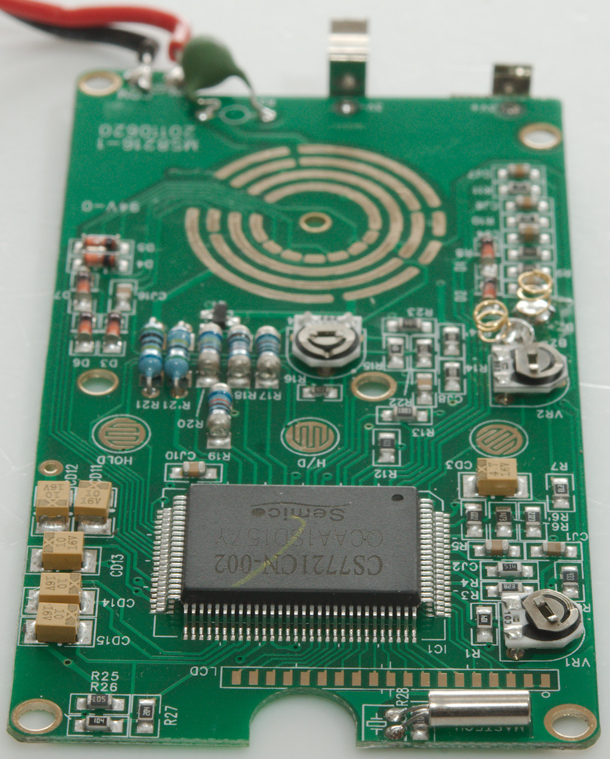
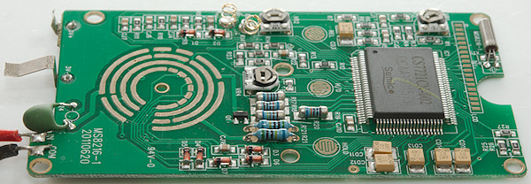
On the input is a PTC (R24), it is not used for all ranges. The main input resistor (R21 & R'21 2x5Mohm) goes directly to the multimeter chip. My guess is that the input protection is a single transistor (Q1), it looks like the 5 diodes (D3..D7) is used for coding range switch to multimeter chip and the two other diodes (D1 & D2) may be rectifier circuit for AC measurement where VR2 is used to adjust it with.
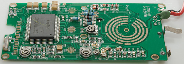
The multimeter chip (IC1 CS7721) handles everything in the meter.
Conclusion
The meter is specified at 600V, but the ranges can only handle 250V in overload.
The meter has about the expected functions for a pocket meter without any current ranges. There is a few problematic areas with it: Range switch must be carefully placed in the correct position it do not snap into position, buzzer is difficult to hear, duty cycle is low performance and the lowest capacitance range is not completely reliable.
Notes
How do I review a DMM
More DMM reviews