DMM Mastech MS8268
This is a cheap DMM with all common function.
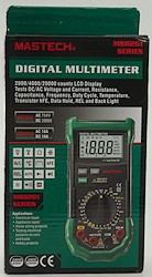
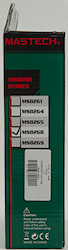
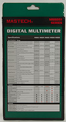
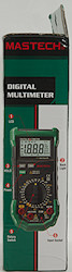
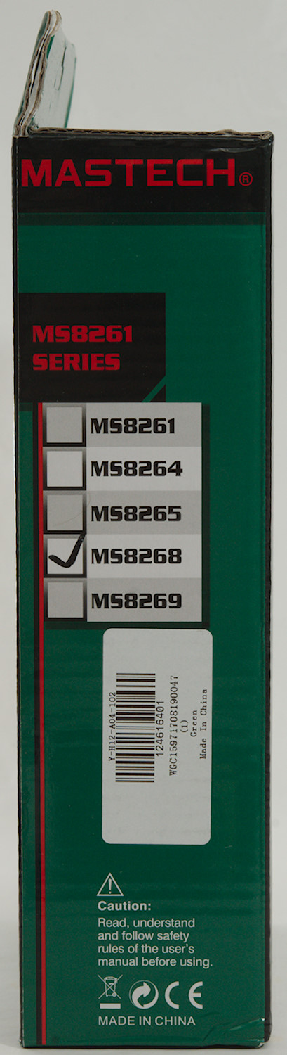
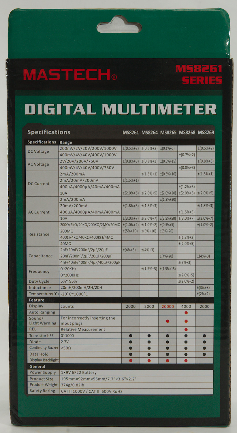
It arrived in a box with a picture of another meter, because the box is used for multiple models. On the box is a comparison between the 5 meters in this series. This model has is the only auto ranging model, this also means it has more current ranges.
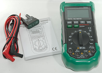
It included the DMM, a pair of probes, a transistor/thermocoupler/capacitor adapter and a manual.
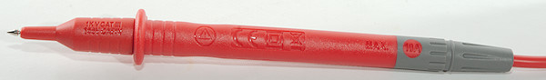
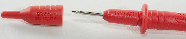
The probes has removable tip covers. The CAT rating is marked on the tip and will change when the cover is removed.
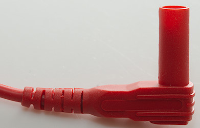
The plug is fully shrouded.
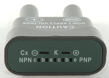
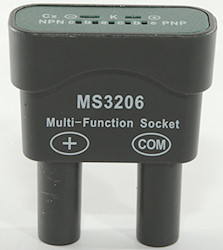
This multi purpose adapter can be used for transistor tester, thermocoupler (Not on this meter) and for capacitor testing.
Supplying the transistor tester socket this way makes it safe (Build-in sockets are not safe).
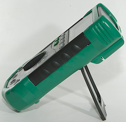
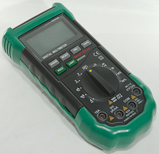
The tilting bale is easy to deploy and can hold the meter both for range switching and for pressing the buttons.
The range switch is fairly soft with good clicks.
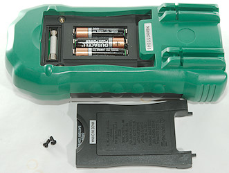
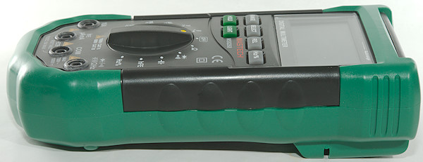
Battery can be replaced without removing the sleeve.
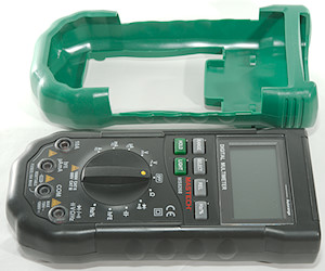
Meter without rubber sleeve,
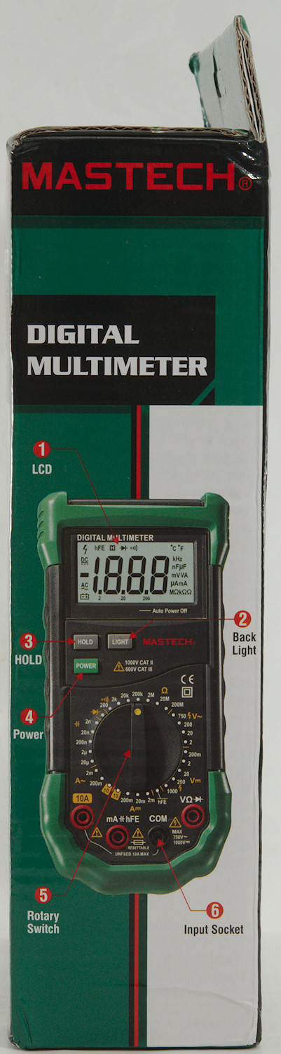
Display
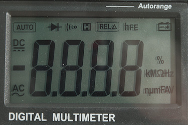
The above picture shows all the segments on the display.
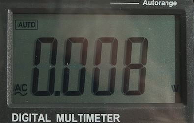
Typical display during usage, it will show the number and what measurement is selected.
Auto means automatic range select.
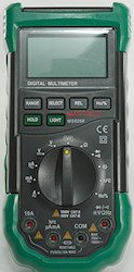
Functions
Buttons:
- Range: Will disable auto range and change range, hold down to activate auto range.
- Select: Select the secondary ranges (ACA and continuity). Hold down during power on to disable auto power off.
- Rel: Shows values relative to current value, will also select manual range. Press again to disable.
- Hz %: Shows frequency and duty cycle in V and A ranges, changes to duty cycle in Hz range.
- Hold: Freezes the display, press again to release
- Light: Turns on background light, will turn off after a few seconds.
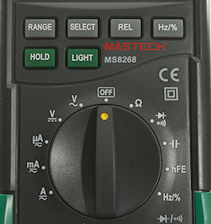
Rotary switch:
- A: Current AC and DC, use SELECT to change.
- mA: Current AC and DC, use SELECT to change.
- uA: Current AC and DC, use SELECT to change.
- V DC: Voltage DC.
- V AC: Voltage AC, use manual range to select mVAC
- Off: Meter is turned off
- ohm: Resistance
- Diode and continuity, use SELECT to change.
- Capacitance: Capacitor.
- hFE: Used together with the adapter to measure transistor gain.
- Hz/%: Frequency and duty cycle, for high bandwidth this selection must be used, it is only for low voltage.
Input
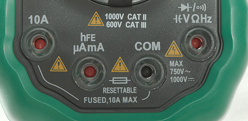
- 10A: High current, it can only withstand 10+ ampere for a short time (Fuse is 10A).
- mAuA: The lower current ranges and hFE range, the selector switch will change between two different shunts, it uses a PTC as fuse.
- COM: The common terminal for all ranges.
- xxx: All other ranges.
The terminals are not deep enough to cover standard banana plugs, but they do connect. The light in the terminals is a very nice feature.
Measurements
- Volt and frequency
- Frequency counter and duty cycle requires a zero crossing on AC and DC ranges, but not on frequency range
- At 1Vrms input frequency range is from 0.5Hz to 450kHz
- 1 VAC is 5% down at 1.5kHz
- Duty cycle works from 7% to above 96% at 10kHz with 4Vpp, precision is within 2.5
- Duty cycle is slow to show the final value.
- Input impedance is 10 to 11Mohm on DC, AC and ACmV
- DC mV range is high impedance below 1.5V, then it will drop to 10-20Mohm.
- Maximum rated voltage is 1000VDC or 750VAC
- Frequency input is about 2Mohm at low voltage because meter is sourcing a small current, at higher voltage it is around 6Mohm
- Rated overload protection for frequency range is 250V AC/DC
- Current
- On the 4000uA, 400mA & 10A range there is an audible alarm when going above range.
- mA & uA range uses a PTC as fuse, i.e. it will automatic recover when over current is removed.
- High mA range is very bad in burden voltage.
- 10A range has a 10A/250V 6.3x32mm fuse
- Ohm, Continuity, diode and capacitance
- Ohm is 0.45V open and 0.17mA shorted
- Continuity is moderate in speed (About 50ms).
- Continuity beeps when resistance is below 30ohm (There is some noise for a few ohms more).
- Continuity is 0.45V open and 0.17mA shorted
- Diode range uses 1.6V, max. display is 0.999V at 0.21mA, max. current is 0.54mA shorted
- 200uF takes about 43 seconds to measure.
- Rated overload protection is 250V AC/DC
- Miscellaneous
- Current consumption of meter is 2.5mA (12mA with backlight and 6mA with two input terminals on)
- Display starts dimming around 3.5V and is just about unreadable at 3.3V, battery symbol show at 3.7V.
- Reading will change slightly with battery voltage: 3 count on a 3.0V reading from 4.5V to 3.5V.
- Backlight only works down to about 3.5V where it gets dim.
- The meter usual need a couple of display update to reach the final value.
- Viewing angle is good, except from the top.
- Display updates around 3 times/sec
- Backlight will automatic turn off in about 5 seconds.
- Will automatic turn power off in about 15 minutes.
- Sockets are not deep enough to cover standard banana plugs, but they will make contact.
- Sockets will light red when a probe is supposed to be in it.
- If a probe is plugged into the wrong socket the correct one will flash red and the buzzer will sound.
- Weight is 283g without accessories, but with rubber sleeve and batteries.
- Size is 192 x 93 x 55mm with rubber sleeve.
- Probes
- Probe resistance 22mOhm for one.
- Probe wire is soft and 80cm long.
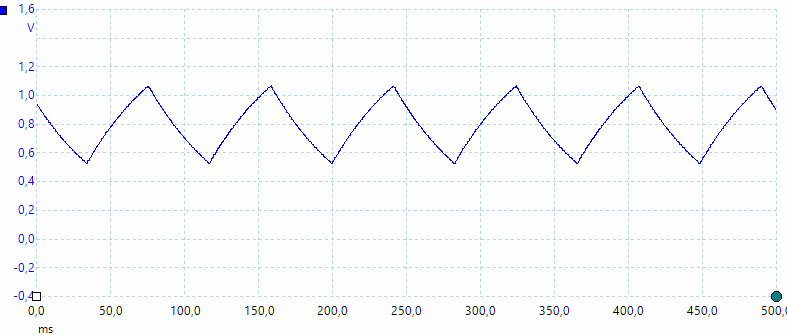
A look at the capacitance measurement waveform.
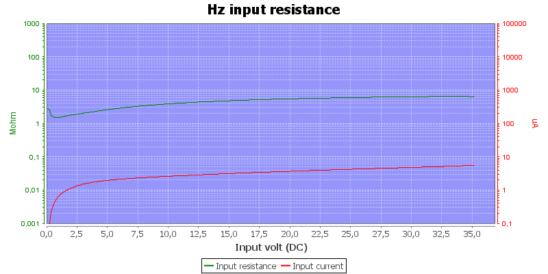
Frequency input resistance.
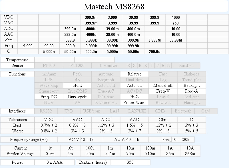
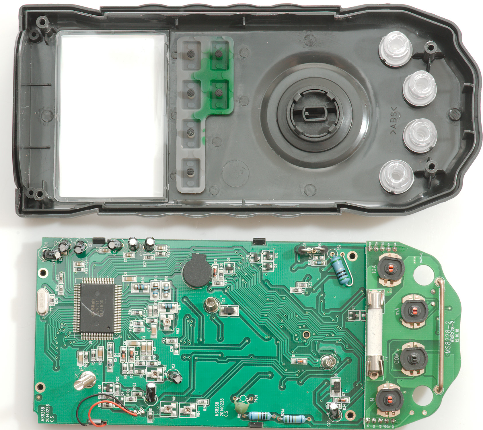
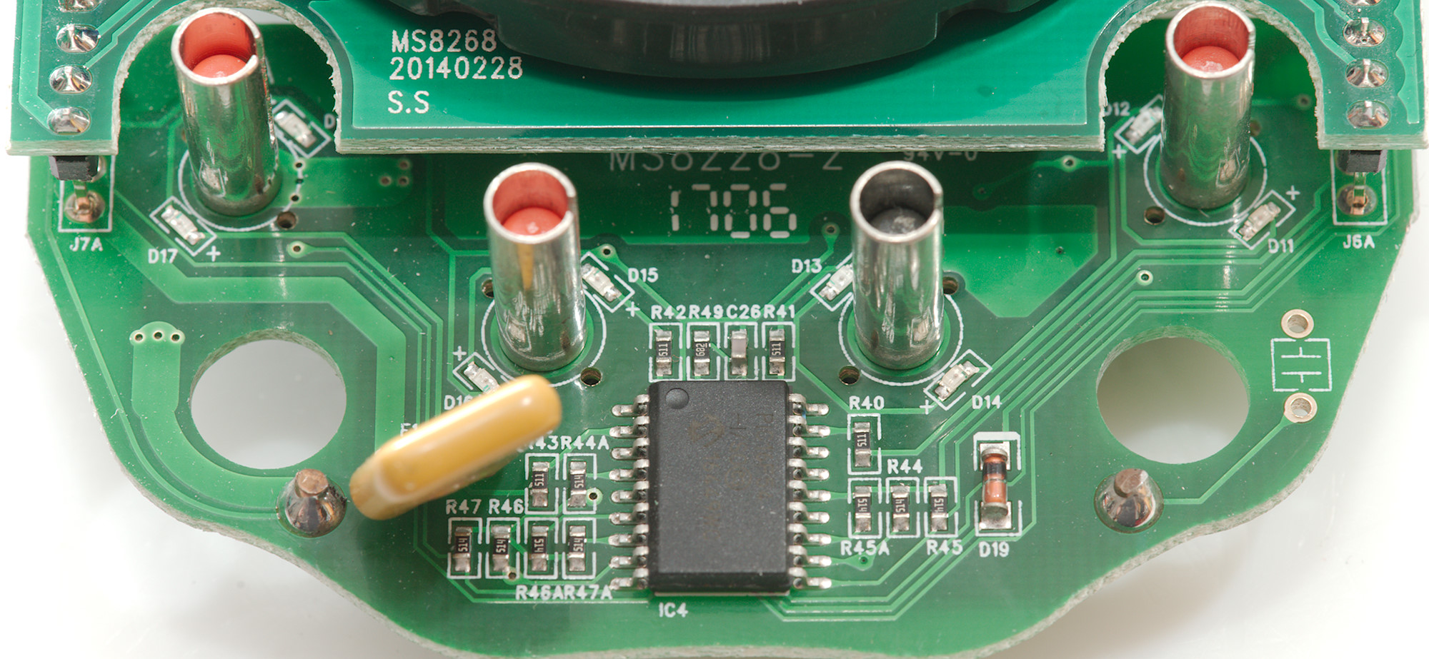
Tear down
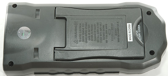
Four screws and the back could be removed.

4 more screws for the circuit board
And 4 clips for the range switch and lcd display cover.
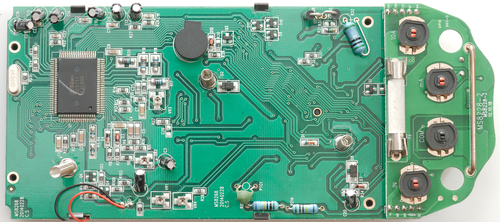
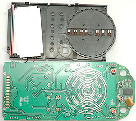
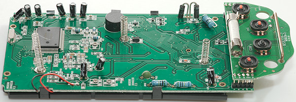
On the side with the voltage input R21A & R21B is the 10Mohm voltage input. The PTC1 is the ohm and capacitance current output.
On the side with current input R32 is the mA shunt and R31 is the uA shunt, D5 and D6 is protection of the shunt resistor.
D2 is protection against reverse mounted batteries.
The meter uses trimmers to adjust the ranges (VT1, VR2, VR3, VR4). The meter chip is called SC9711.
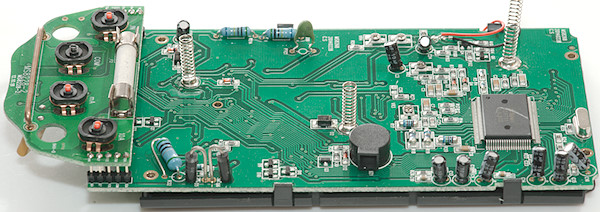

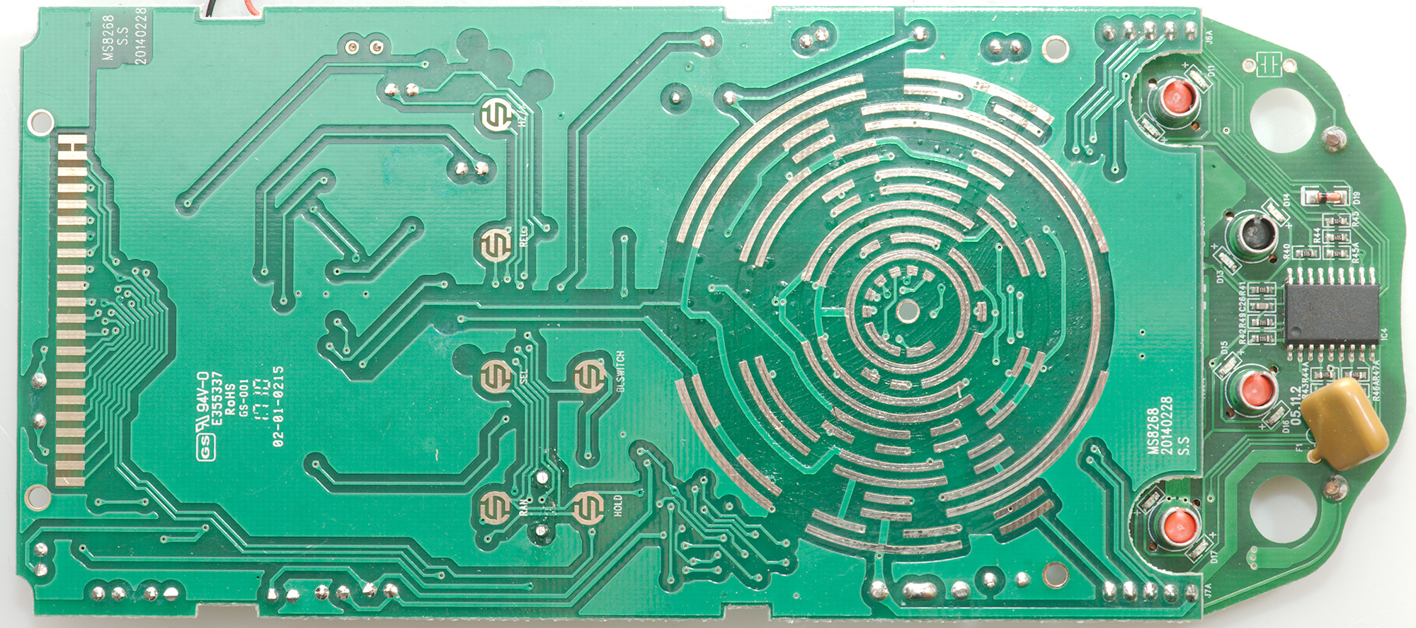
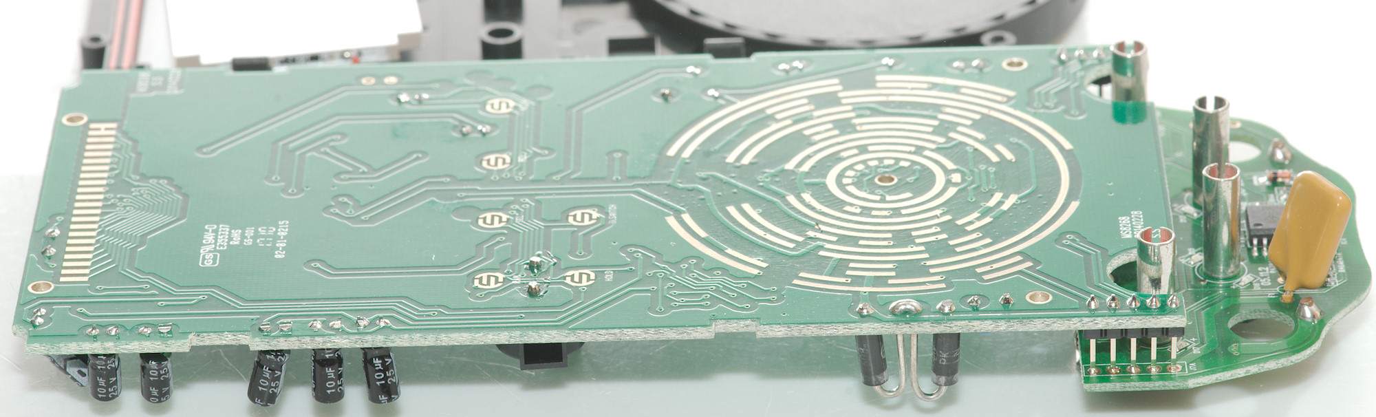
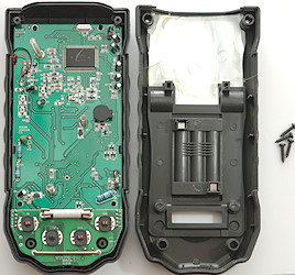
There is no parts on this side, only the lcd connection, the buttons and the range switch.

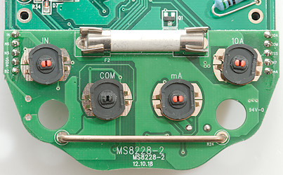
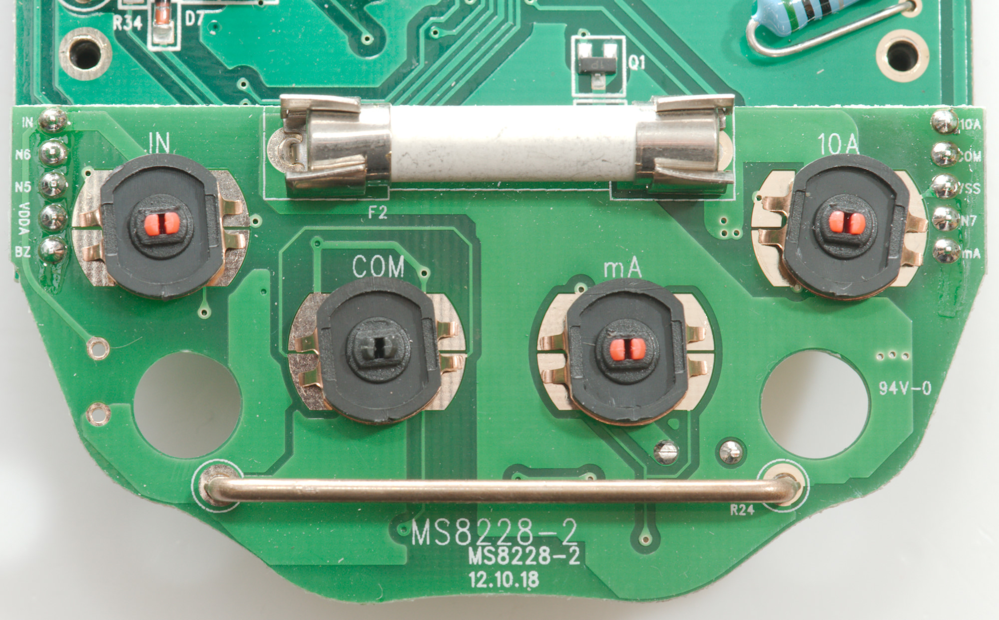
All the input terminals is on an small circuit board together with a 10A fuse and the 10A shunt. Each terminal has a switch at the back, making it possible to detect when a banana plug is put into it.
The long fuse it not going to help much, the tracks on the circuit board are very close together.
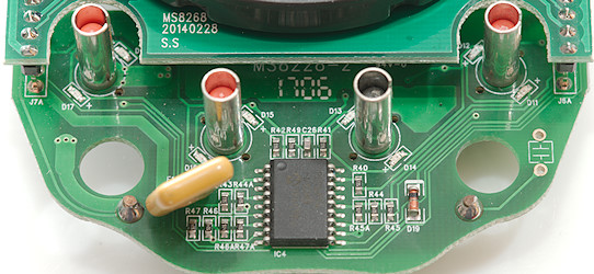
On this side the terminals can be seen with two leds around each of them. The current range PTC is also here. The chip is a PIC16F54 that controls the leds, depending on what plugs are inserted.
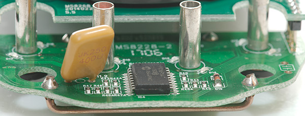
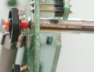
A socket with a banana plug into it, as can be seen the switch part is moved away from the circuit board.
Conclusion
As usual this type of cheap meters do not have much safety and probably do not live up to its CAT rating, i.e. keep it away from high voltage and lots of current.
With that said it is a nice meter for occasionally hobby usage in the house and on the bench, due to the led indication of where to connect the probes and the resetable fuse, but the current ranges has a very high burden voltage, i.e. measuring at a few volts will not work correctly. The backlight cannot really be turned on, it can only be activated to get a single reading, because it turns off very fast.
Notes
How do I review a DMM
More DMM reviews