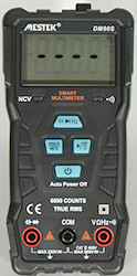
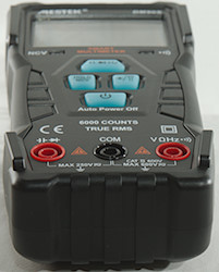
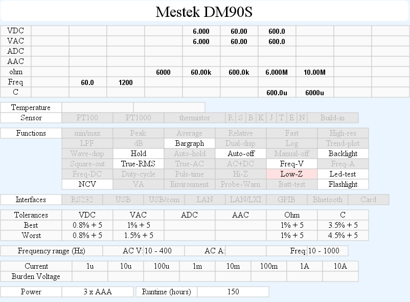
DMM Mestek DM90S
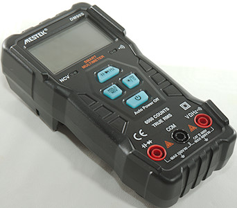
This is a automatic meter with a limited amount of ranges.
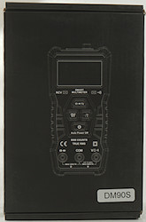
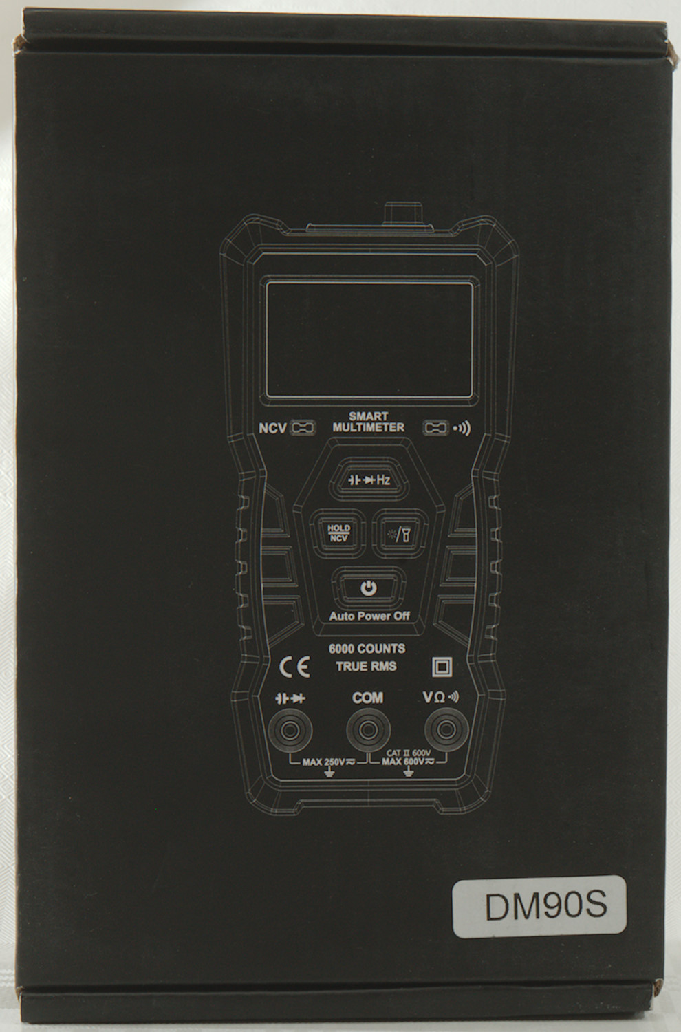
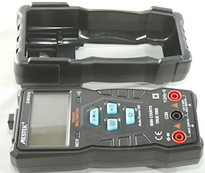
I got the meter in a cardboard box with a drawing of the meter
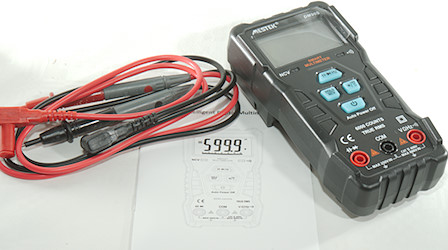
It included the DMM, a pair of probes and a manual.
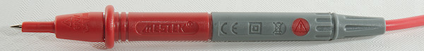
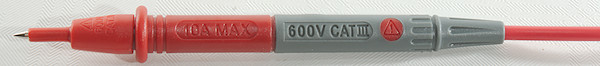
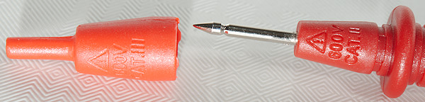
The probes are rated for 600V CAT III and CAT II without the tip cover.
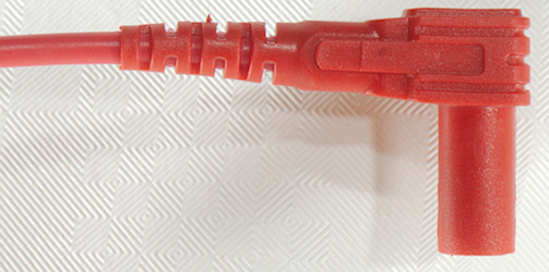
The shrouded plug is the short variety.
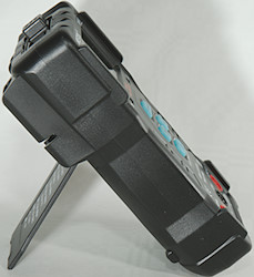
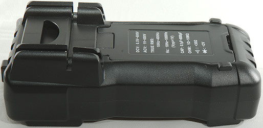
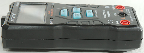
Using the switches requires holding the meter.
Display
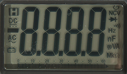
The above picture shows all the segments on the display, not all of them are used.
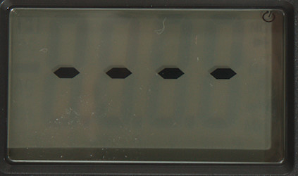
Display when meter is idle, it will show four bars and wait for a value.
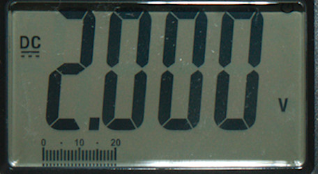
When measuring it will show the value and range.
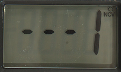
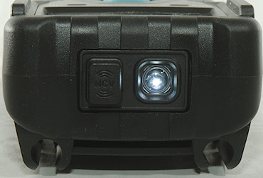
The NCV shows bars when nothing is detected and will use a number from 1-3 to show field strength.
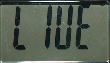
A bug in the meter, it shows LIVE while measuring a 6uF capacitor. I did not get it to show LIVE by connecting either of the input terminals to live mains voltage. According to the manual it is used to indicate when voltage is feed into these terminals, but it do not detect 10V DC/AC.
Functions
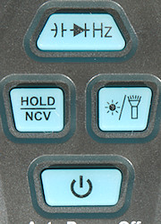
 : Switch between diode/capacity or select frequency display
- HOLD/NCV: A short press will freeze the current value, while held down the meter is in NCV mode.
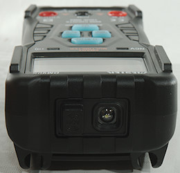
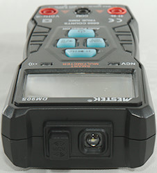
 : Turn backlight on, a long press will turn backlight and flashlight on.
 : A long press will turn the meter on or off.
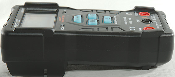
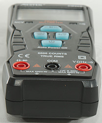
Input
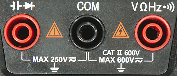
 : Input for diode test and capacity measurement, meter will automatic select it when connected.
- COM: The common terminal for all ranges.
 : Input for voltage, resistance, continuity, frequency.
Measurements
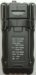
- Volt and frequency
- At 2Vrms in AC voltage frequency range is from 9Hz to 1.2kHz
- 1 VAC is 5% down at 1kHz (RMS will not work at the frequency).
- Frequency input requires a zero crossing or it will assume DC voltage.
- Switch to DC volt at around 0.4V
- Switch to AC volt at around 0.8V
- Input impedance is 900kohm on DC and AC, except below 4 volt where it will raise to 10Mohm.
- Overload protection is rated for 600V on volt and ohm range.
- Current
- Meter cannot measure current.
- Ohm, Continuity, diode and capacitance
- Ohm needs about 0.5s to measure 100ohm
- Ohm & continuity is combined, when resistance is below 75ohm (Real value 90ohm)/75mV (Real value 0.15V) the display shows ohm,
- Ohm/continuity is 2.0V open and 0.01mA shorted
- Continuity is slow (About 300ms).
- Continuity beeps when resistance is below 30ohm.
- Diode range uses 2.8V, max. display is 2.000V at 0.15mA, max. current is 0.6mA shorted
- Capacity/diode input will sometimes switch to LIVE display, instead of measuring the component.
- 10uF takes about 0.3 seconds to measure.
- 6000uF takes about 5 seconds to measure.
- Overload protection is rated for 250V rms on diode/capacity range.
- Miscellaneous
- The bargraph has 60 steps.
- Current consumption when meter is off is around 7uA, this is insignificant.
- Current consumption of meter is 6mA in idle, 25mA with backlight and 43mA with backlight and flashlight.
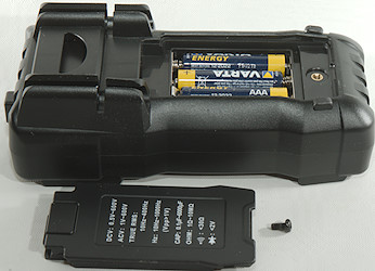
- Meter works down to 2.4V where display is faded, battery symbol show at 3.7V.
- Reading increased below 3.1V
- Backlight and flashlight changes with voltage and are nearly off at 2.5V
- The meter usually shows correct value in first update, but display jumps one or two counts up/down.
- Viewing angle is good, except from top.
- Display updates around 5 times/sec
- Backlight will automatic turn off in about 35 seconds.
- Flashlight will automatic turn off in about 35 seconds.
- Will automatic turn power off in about 6 minutes.
- Standard probes nearly be pushed fully down.
- Weight is 229g without accessories, but with rubber sleeve and batteries.
- Size is 149 x 72 x 47mm with rubber sleeve.
- Probes
- Probe resistance 47mOhm for one.
- Probe wire is soft and 76cm long.
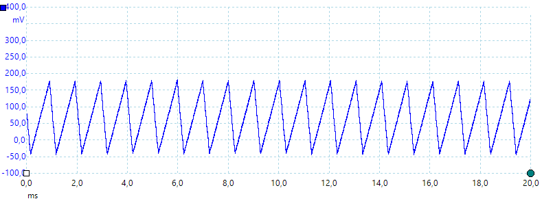
A look at the capacitance measurement waveform.
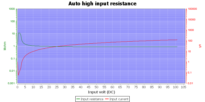
The voltage input is only 900kOhm input impedance.
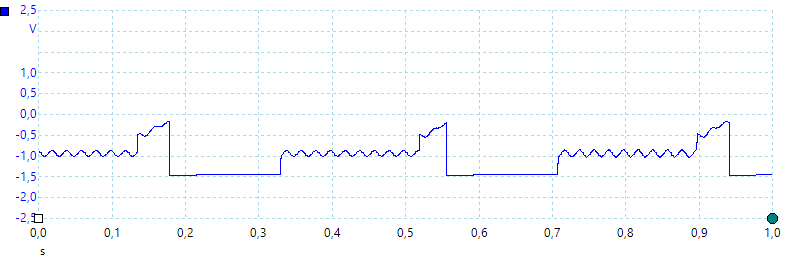
Voltage input uses negative voltage to measure resistance. In this picture the input is loaded with 10Mohm from the oscilloscope.
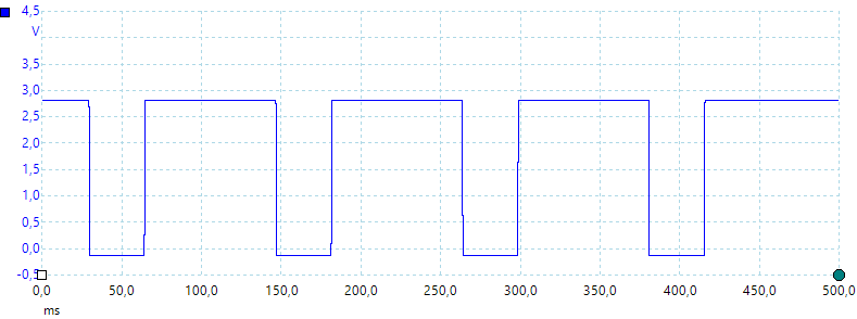
The diode test input is also pulsing, but with a higher voltage to detect a diode.
Meter cannot handle a combination of DC and AC when DC is highest.
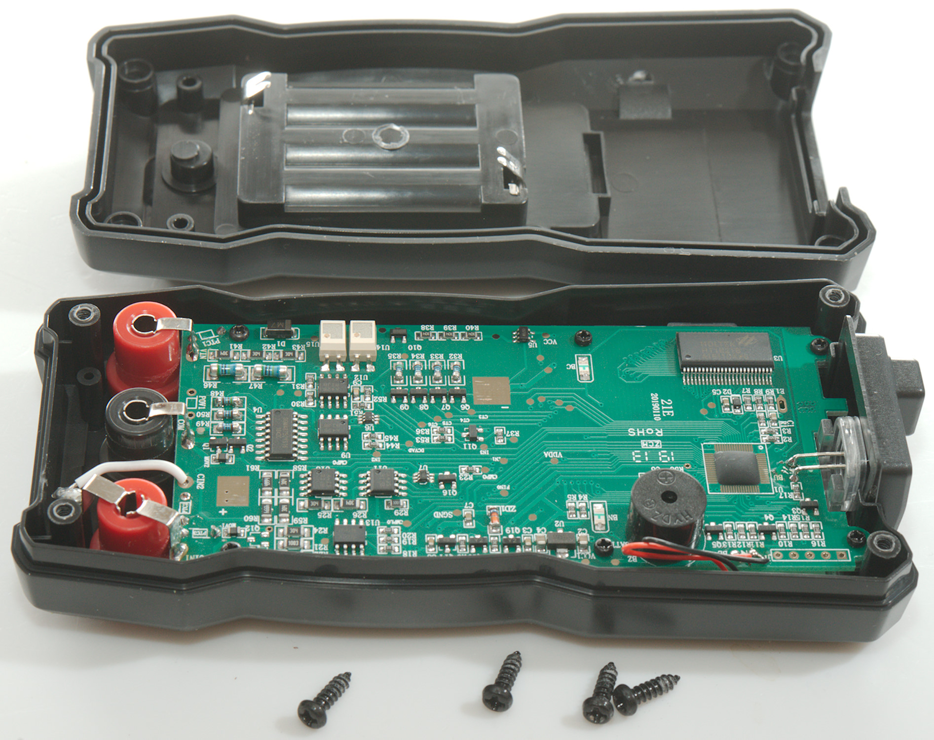
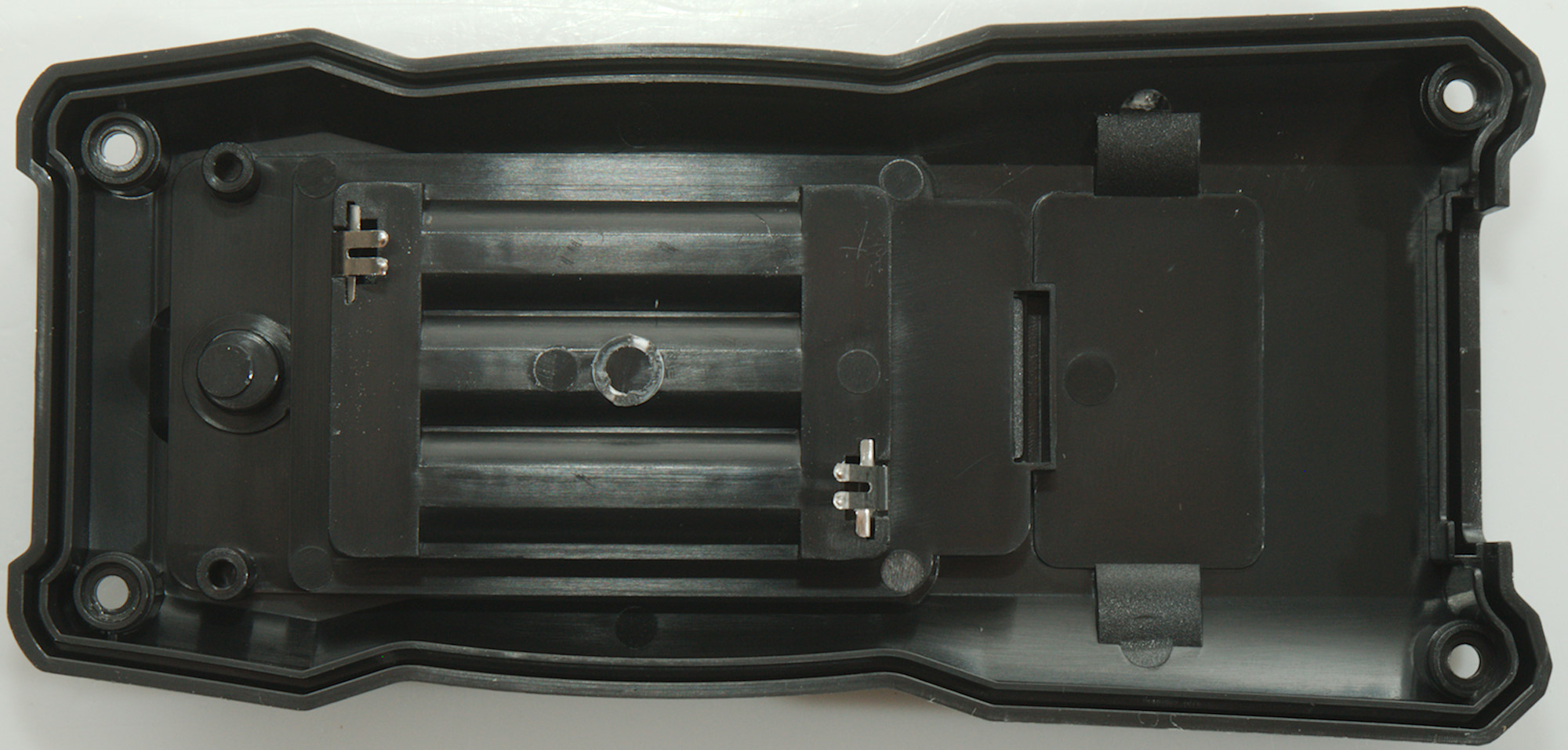
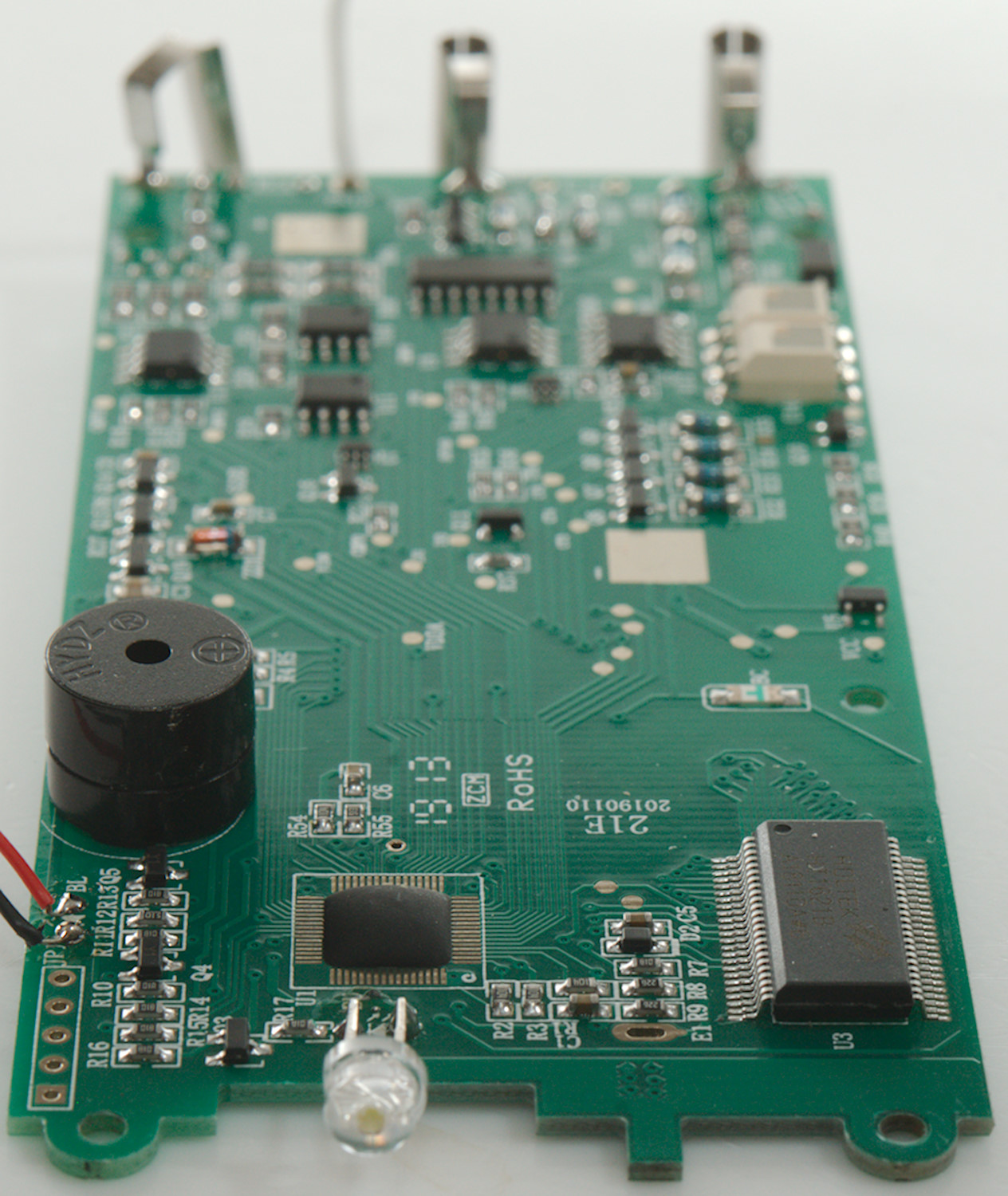
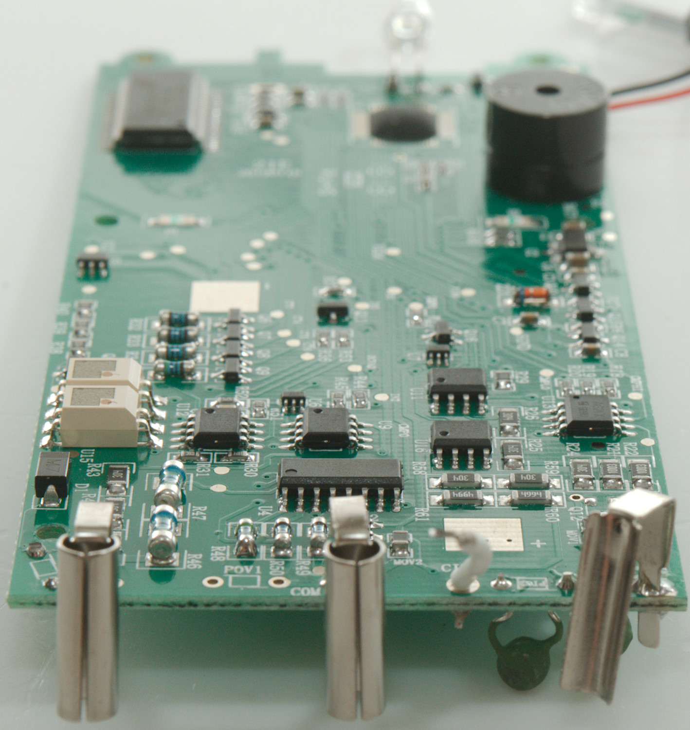
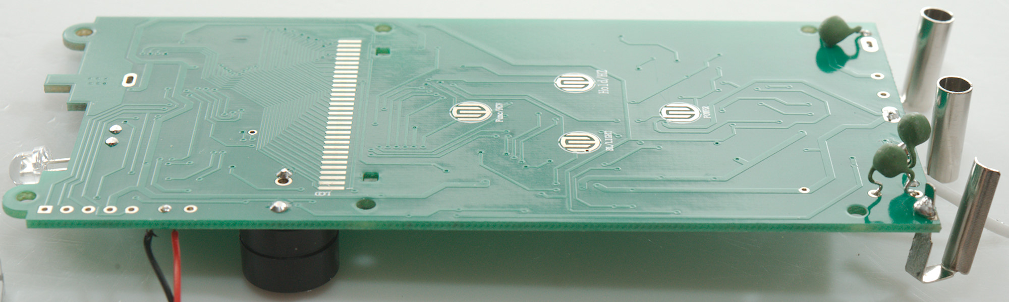
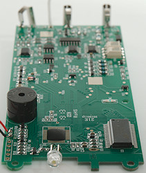
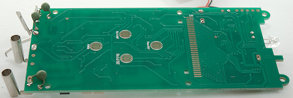
Tear down
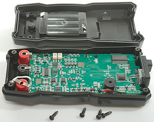
I had to remove four screws to open the meter.
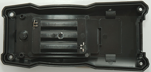
The detection of diode/capacity input is done with a split terminal, as can be seen here.
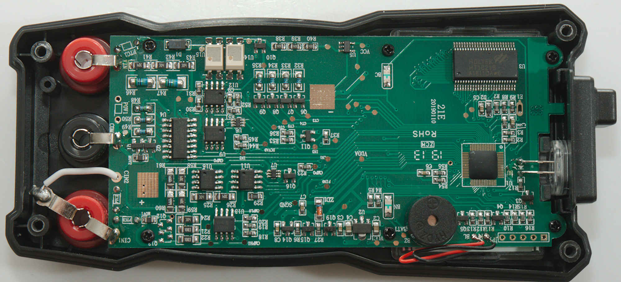
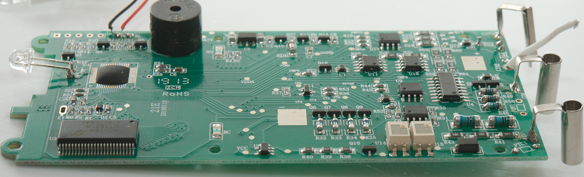
Getting the circuit board out was 6 screws and I had to unsolder one wire.

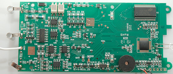
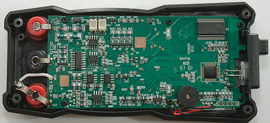
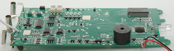
The voltage input has the usually 3 input paths: a high impedance (R46 & R47: 2x5Mohm), a medium impedance (R41, R42, R43: 3x300kOhm) and a low impedance (PTC1, D1, U14 & U15: Electronic relay). It looks like the ohm circuit may be partially implemented with discrete components. There is a transistor to open for the circuit (Q10) and four transistors (Q7, Q7, Q8, Q9) to select four resistors (R32, R33, R34, R35: 1kOhm, 10kOhm, 100kOhm, 1Mohm).
The circuit has a couple of opAmps (U9, U11, R12, U16: A42S: LMV358) and some multiplexer (U4: SGM48752: 2x4Mux) (U6: 3157: 74LVC1G3157: 2 to 1) (U7: 3167: maybe PI5A3167C).
The diode/capacity input uses two PTC's (PTC2 & PTC3) and MOV's (MOV1 & MOV2) for protection. MOV2 do probably not do much, because it is parallel with a transistor pair(Q1 & Q2), before it goes to U7. The other path splits into 3 (R21, R22, R24-R25-R26: 100kOhm, 100kOhm, 3x300kOhm). The sense part has its own resistors (R58, R59, 60, R61: 300kOhm, 300kOhm, 4.999Mohm, 4.999Mohm).
Everything ends up in the multimeter IC (U1), with the display driver in another chip (U3: HT1621).


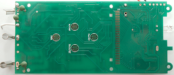
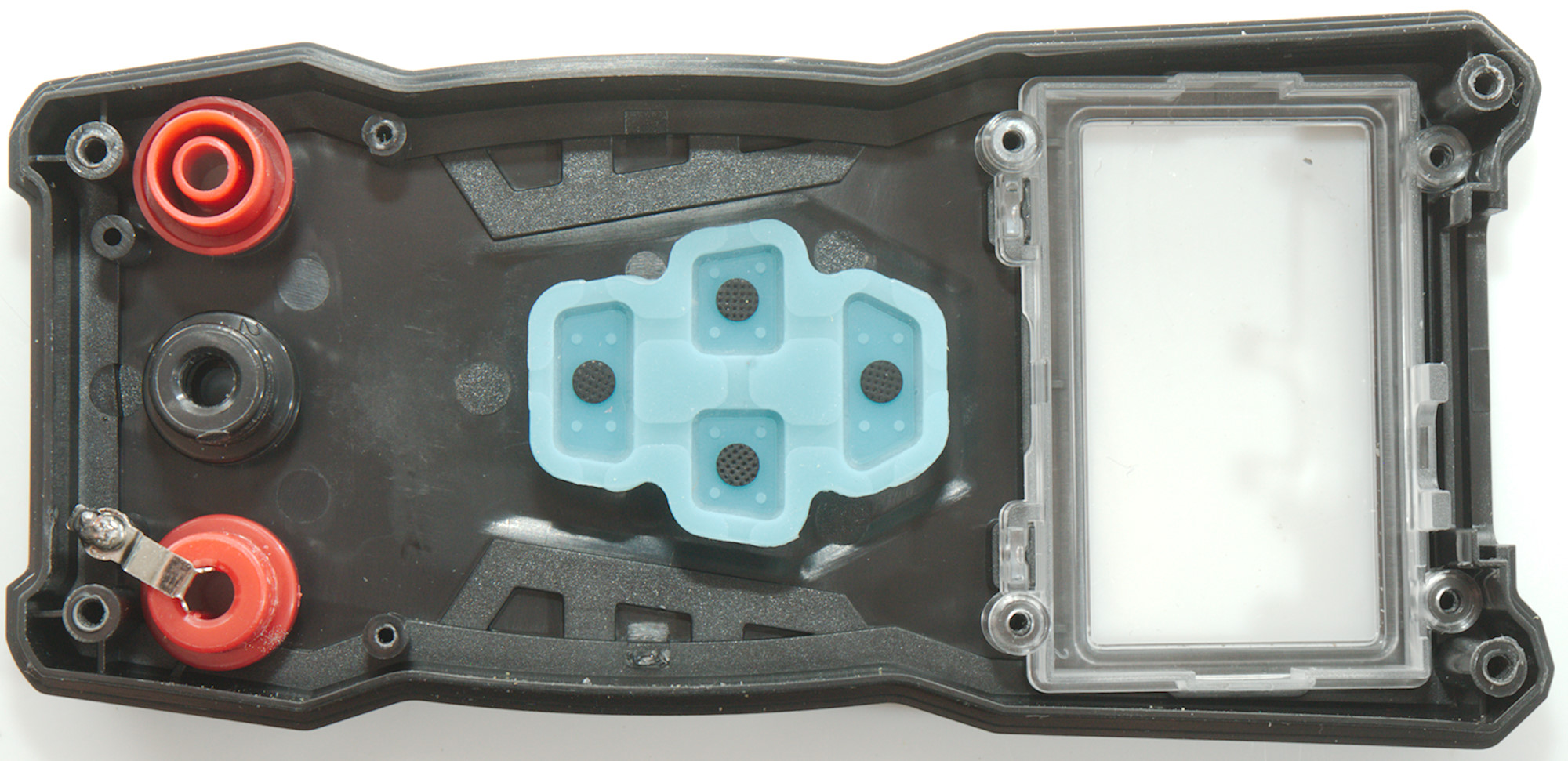
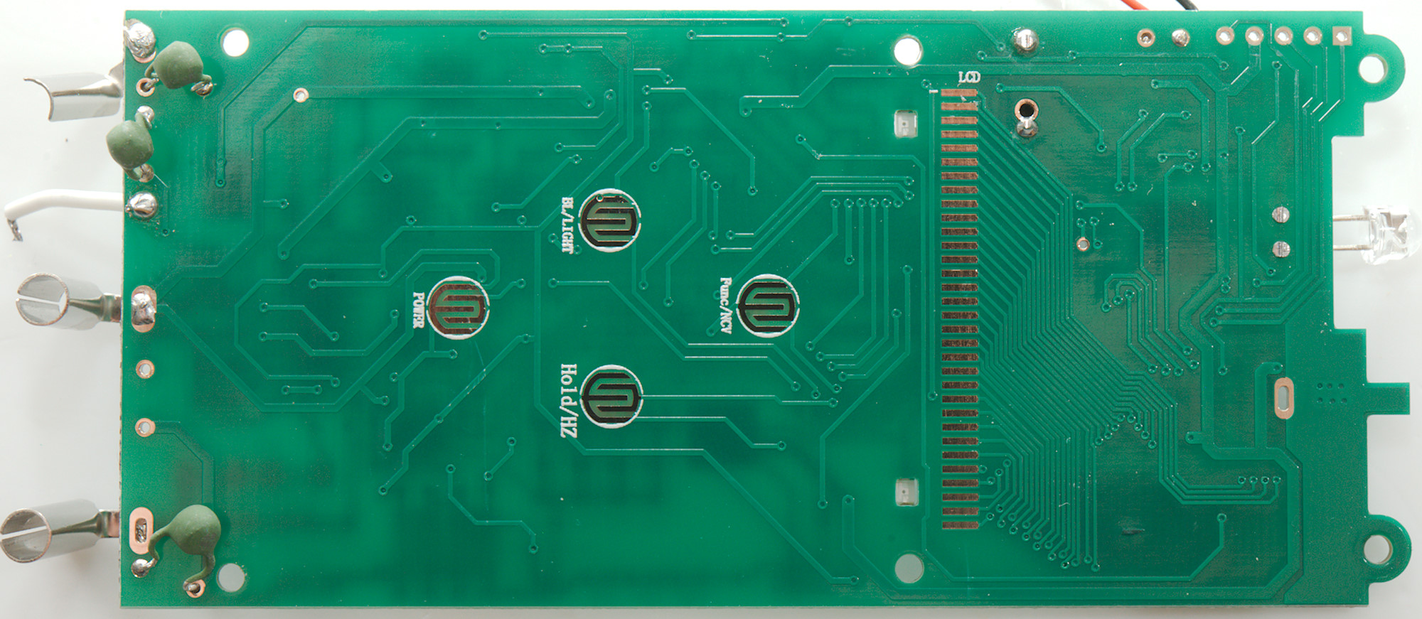
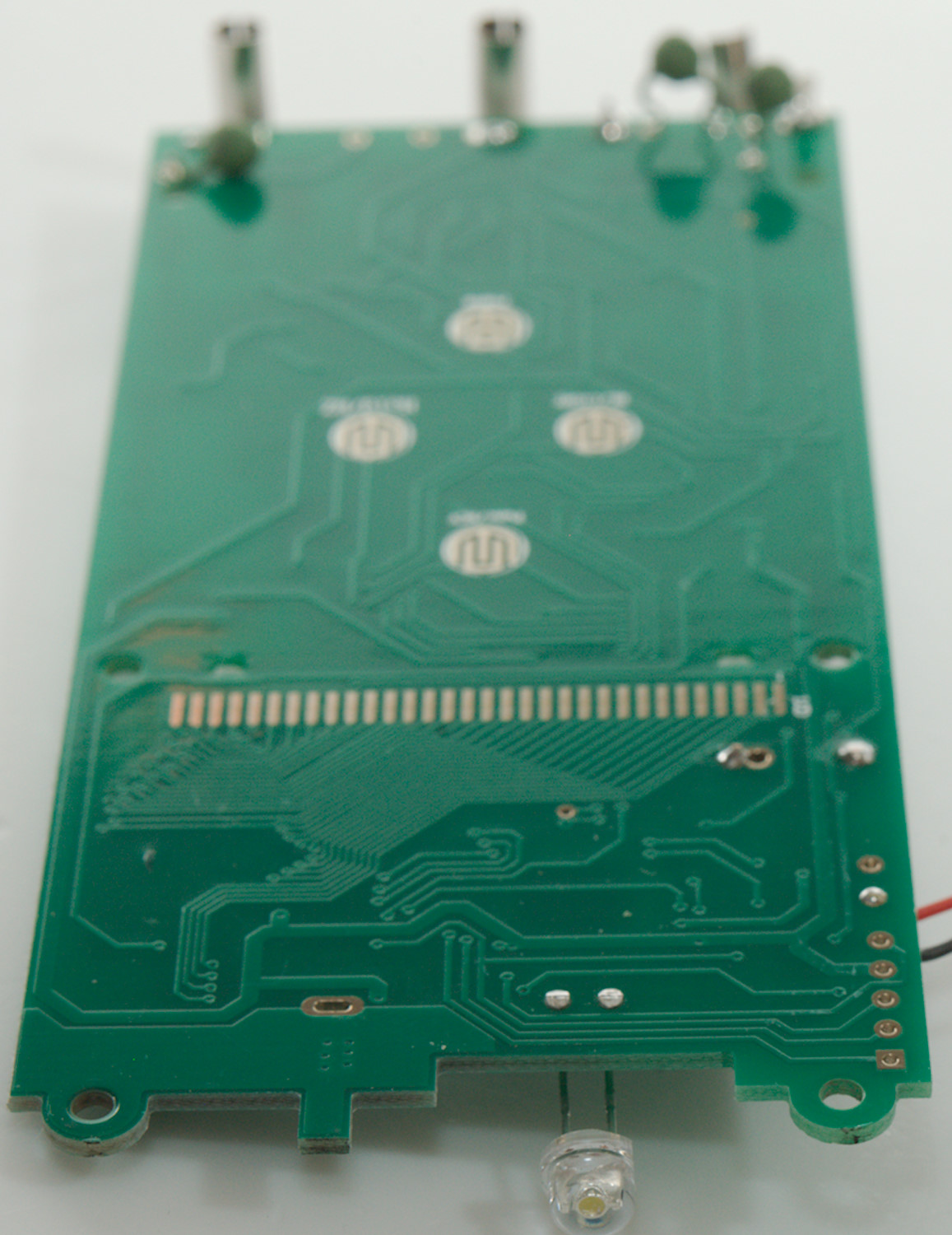
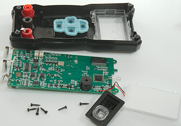
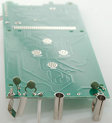
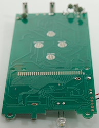
On this side is only the pads for the LCD display and buttons, together with the PTC resistors.
The leds for the front are firing through holes in the circuit board from the other side.
The button pads are not correctly marked with functions.

Conclusion
This meter has a fairly low CAT rating, but only one of the inputs are marked to comply with it, that is not correct.
The amount of ranges and functions on this meter is fairly low and the idea to avoid a range switch and instead have to move the input plug between terminals is not something I approve of (Except for current).
Notes
The multimeter was supplied by banggood.com for review.
How do I review a DMM
More DMM reviews