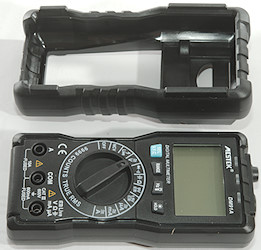
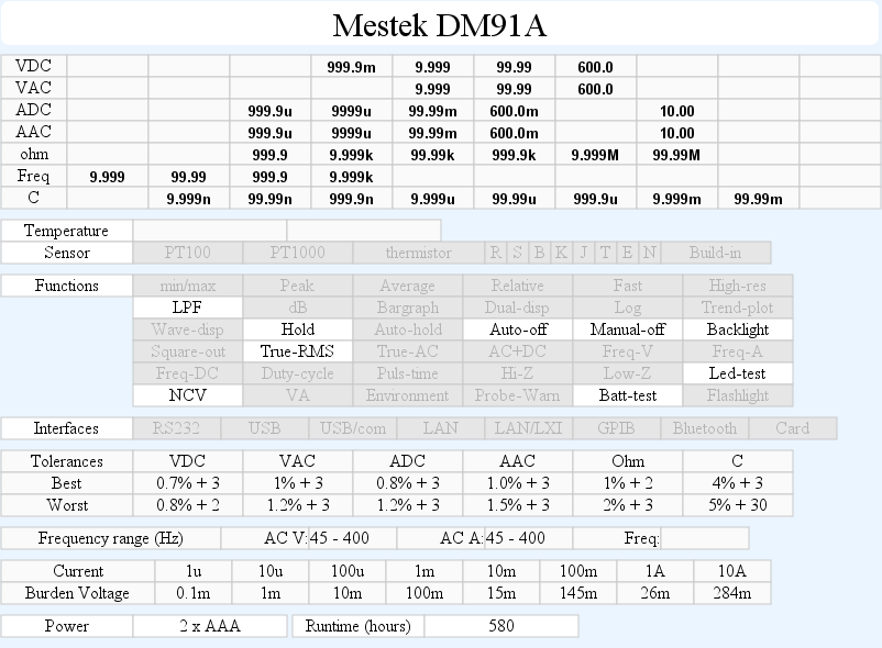
DMM Mestek DM91A
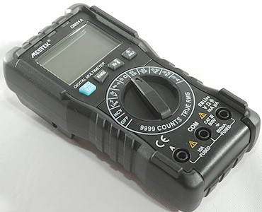
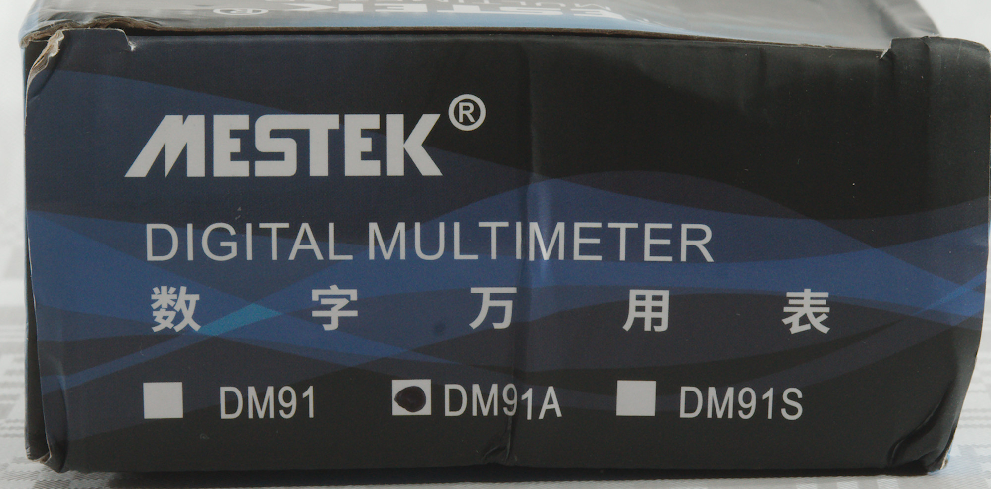
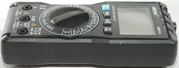
This is a smaller meter with a good collections of ranges. Do not get the low end version of the meter without the A in the number!
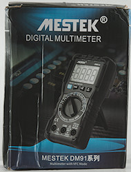
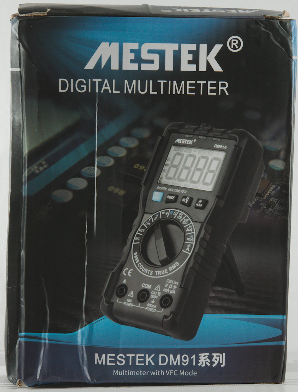
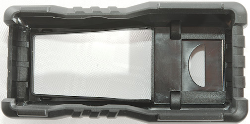
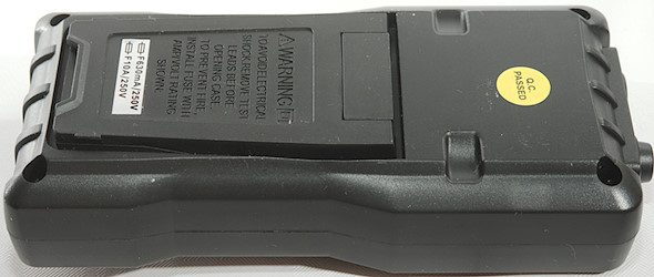
I got the meter in a cardboard box with a photo of the meter
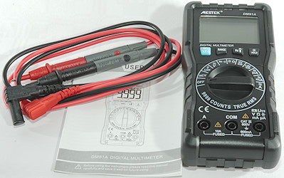
It included the DMM, a pair of probes and a manual.
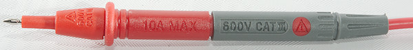
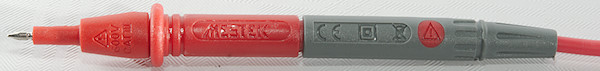
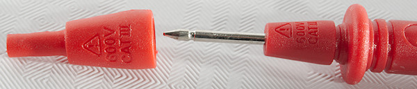
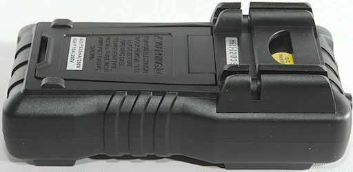
The probes are rated for 600V CAT III & CAT IV and CAT II without the tip cover.
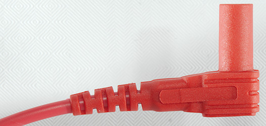
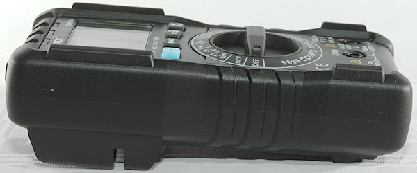
The shrouded plug is the slightly short variety.
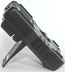
The range switch is a bit difficult to use single handed when meter is on the tilting bale, it slides around.
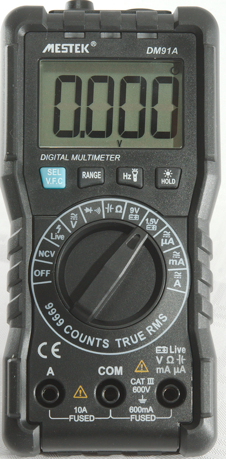
Display
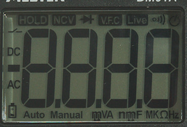
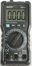
The above picture shows all the segments on the display, most of the symbols are used.
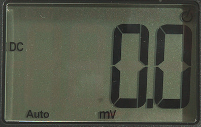
Typical display during usage, it will show the number and what measurement is selected.
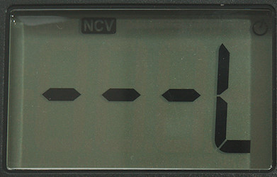
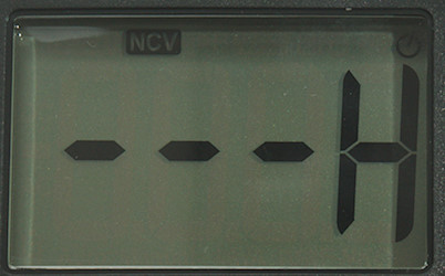
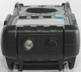
The NCV shows bars, but the indication is a L or H together with one green or two red leds and the buzzer.
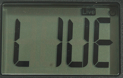
When live voltage is present on the red input terminal it will show LIVE and use the two red leds and the buzzer.
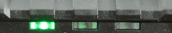
The green led is used for NCV low detection and for continuity.
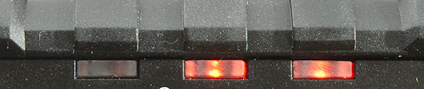
The two red leds always lights together and is used for NCV high and LIVE detection.
Functions
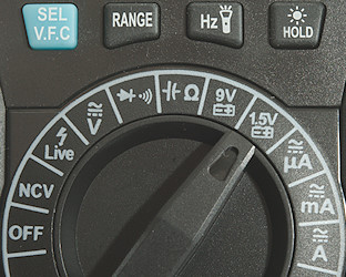
Buttons:
- Sel (Blue): Select AC and capacity, hold down for VFC mode in VAC.
- Range: Will disable auto range and change range, hold down to activate auto range.
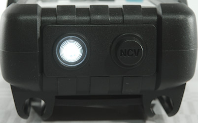
- Hz: Select frequency display in AC modes, hold down for flashlight.
- Hold: Freezes the display, hold down for backlight.
Rotary switch:
- Off: Meter is turned off
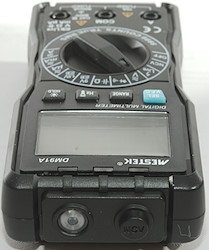
- NCV: Non-contact voltage or electric field detection.
- Live: Single wire live voltage detection.
- V: VDC/VAC and frequency, only VDC has mV range.
 : Combined continuity and diode mode.
 : Resistance and capacitance.
- 9V: 9V battery tester with load.
- 1.5V: 1.5V battery tester with load.
- uA: Current DC and AC (Use Select to change between them).
- mA: Current DC and AC (Use Select to change between them).
- A: Current DC and AC (Use Select to change between them).
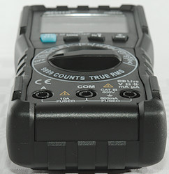
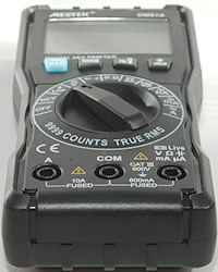
Input
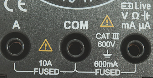
- 10A: High current input
- COM: The common terminal for all ranges.
- xxx: All other ranges.
Measurements
- Volt and frequency
- At 100mVrms in AC voltage frequency range is from 2Hz to 4.3kHz
- At 1Vrms in AC voltage frequency range is from 1.1Hz to 6.9kHz
- 1 VAC is 5% down at 1.7kHz (RMS will not work at the frequency).
- With VFC 7 VAC is 5% down at 0.7kHz (RMS will not work at the frequency).
- Frequency input requires a zero crossing.
- Input impedance is 7..11Mohm on DC and AC, mVDC is 11Mohm.
- Overload protection is 600VDC and 600VAC.
- Current
- uAmA current is protected by a 0.63A/250V 5x20mm ceramic fuse.
- 10A current is protected by a 10A/250V 5x20mm ceramic fuse.
- The mA range has an audible alarm at 600mA.
- The 10A range has an audible alarm at 10A.
- Current ranges must only be used up to 250VAC and 5-10A not more than 10 seconds.
- Ohm, Continuity, diode and capacitance
- Ohm needs about 2.8s to measure 100ohm
- Ohm is 1.0V open and 0.39mA shorted
- Continuity is slow (About 200ms).
- Continuity beeps intermittent when resistance is below 30ohm.
- Continuity beeps when resistance is below 16ohm.
- Continuity & diode is combined, when resistance is below 75ohm (Real value 90ohm)/75mV (Real value 0.15V) the display shows ohm, when above voltage.
- Continuity/diode is not very precise at low values, but 0.3V and above is fine for diode.
- Continuity/diode range uses 3.2V, max. display is 3.000V at 0.15mA, max. current is 1.7mA shorted
- 10uF takes about 4.3 seconds to measure.
- 70000uF takes about 10 seconds to measure.
- Overload protection is not rated, but manual warns against any voltage.
- Miscellaneous
- 1.5V battery load resistor is around 33ohm, i.e. a 30mA load at 1V
- 9V battery load resistor is around 290ohm, i.e. a 31mA load at 9V
- Current consumption of meter is 1.2 to 1.8mA depending on range (Mostly 1.6mA), with backlight it is up to 4mA, with both flashlight and backlight it is 10mA.
- Meter works down to 2.1V where it turns off, battery symbol show at 2.3V.
- Reading do not change when voltage drops.
- Backlight and flashlight changes with voltage and are nearly off at 2.5V
- The meter needs a couple of display update before it shows the correct value.
- Viewing angle is good, except from top.
- Display updates around 4 times/sec
- Backlight will automatic turn off in about 60 seconds.
- Flashlight will automatic turn off in about 14 seconds.
- Will automatic turn power off in about 15 minutes.
- Standard probes cannot be pushed fully down.
- Weight is 222g without accessories, but with rubber sleeve and batteries.
- Size is 149 x 72 x 47mm with rubber sleeve.
- Probes
- Probe resistance 50mOhm for one.
- Probe wire is soft and 76cm long.
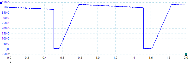
A look at the capacitance measurement waveform.
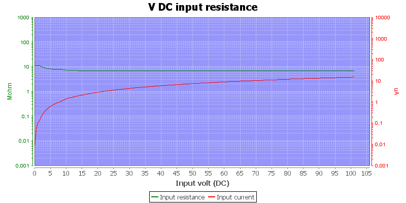
The voltage input is not the usual 10-11Mohm, it is lower at higher voltages.
The DC voltage ranges is at the edge of specified tolerance.
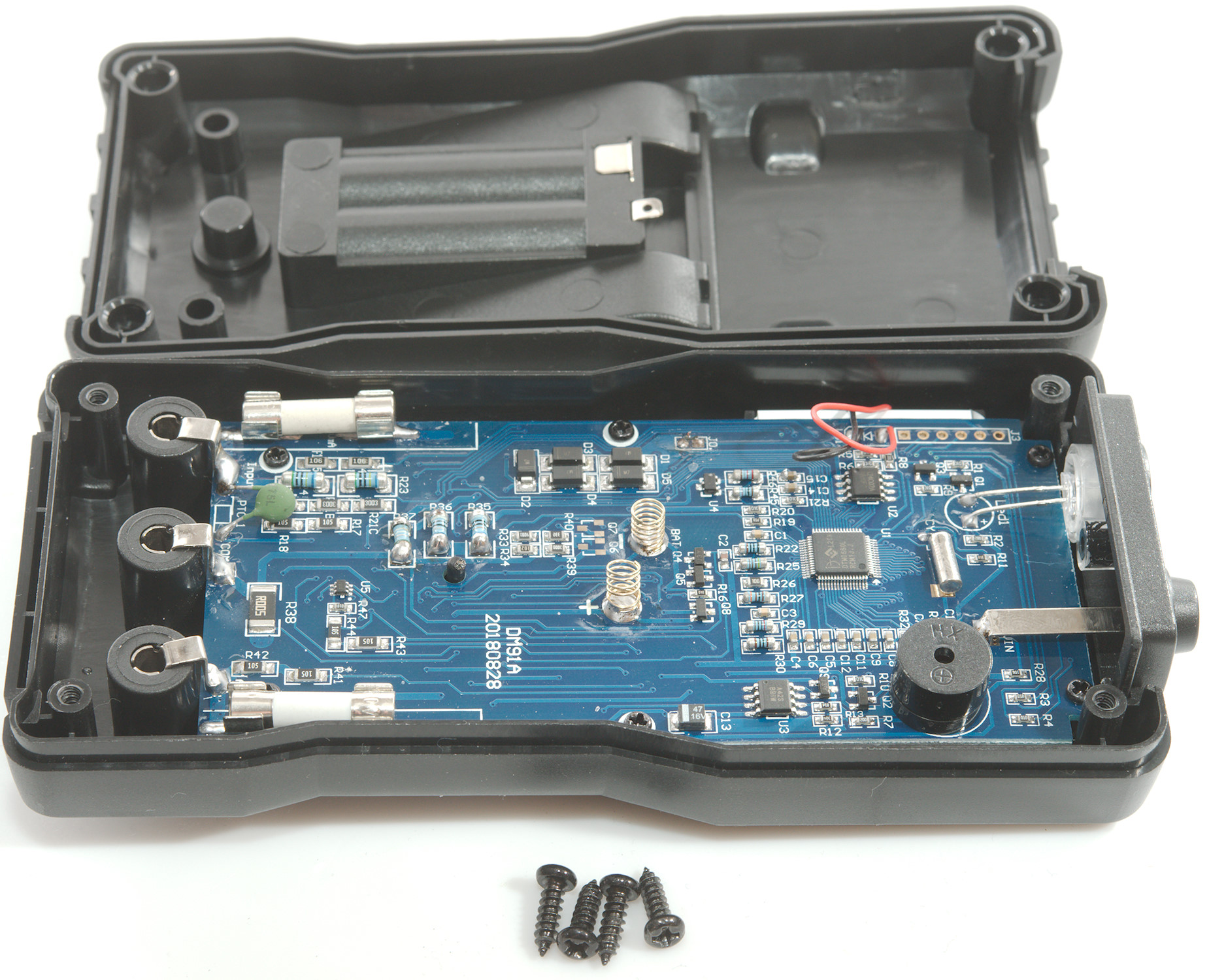
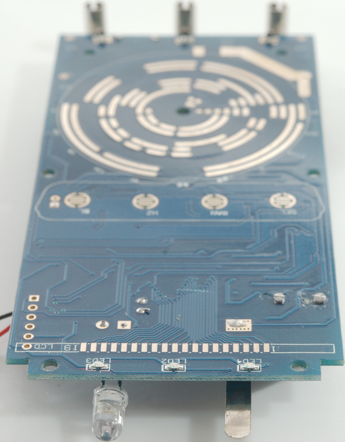
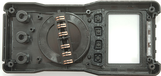
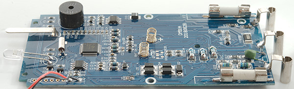
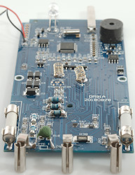
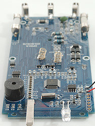
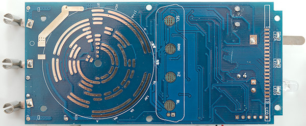
Tear down
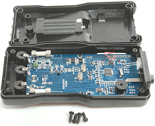
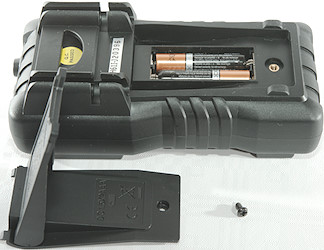
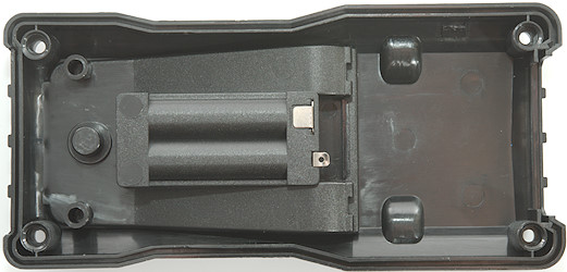
For opening the meter I had to remove the battery door, rubber sleeve and four screws.
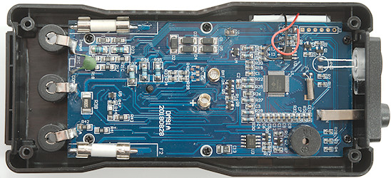
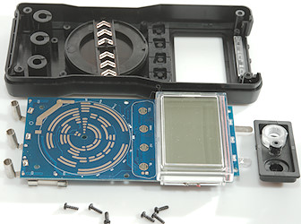
There was 6 screws more before I could get the circuit board out.
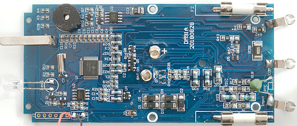
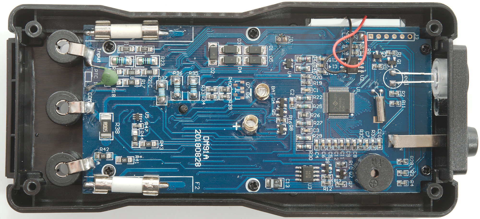
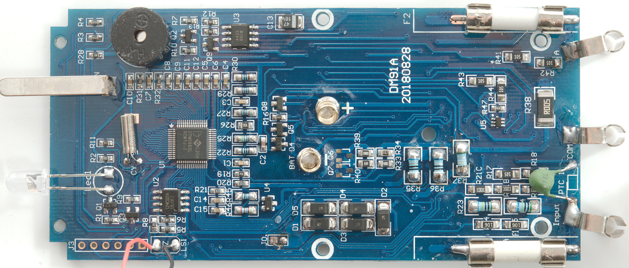
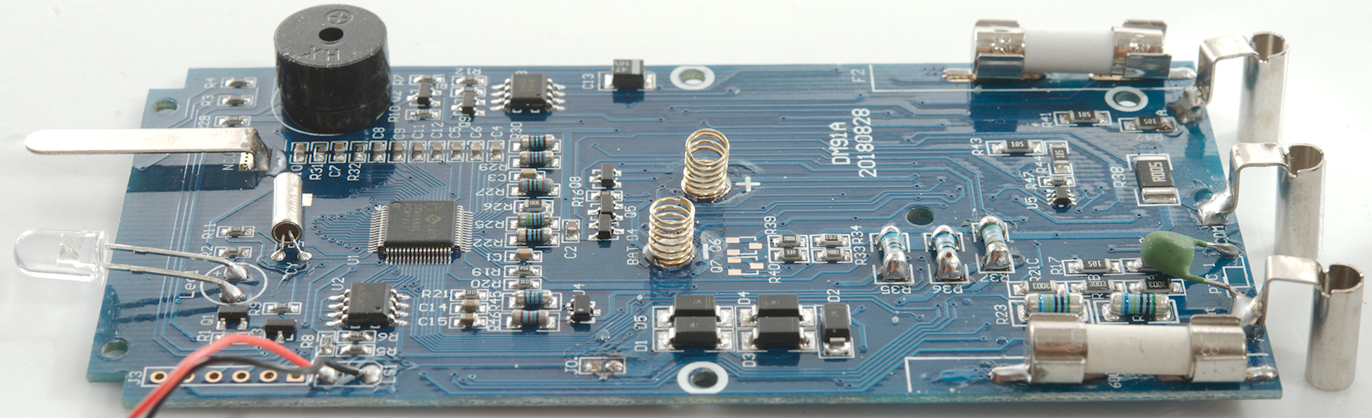
The 10A input has a SMD resistor (R38: 0.005ohm) at half the usual value, the 10A fuses use a SMD mounted fuse holder that is barely soldered to the circuit board. The mA input uses a MELF resistor (R37 ; 0.99ohm) and the uA input uses two resistors (R35, R36): 90ohm + 9ohm), but mA and uA has a diode bridge (D1..D5) for protection. The 1.5V battery range uses a small SMD resistor (R40: 33ohm), the 9V battery range uses the resistor next to it (R39: 300ohm). It looks like there is space for a transistor pair (Q6 & Q7) to protected the two resistors, as it is now they can easily fry on over voltage. Voltage input has the two MELF resistors in series (R23 & R24: 2x5Mohm). There is also a 20Mohm (2x10Mohm), a 900kOhm (3*300kOhm) and a 2Mohm (R17 & R18: 1x1Mohm) input paths. The 20Mohm is probably LIVE detect and the 900kOhm for ohm ranges. The 20Mohm path must be the reason for the 7Mohm input impedance, because they are always connected.
In ohm, continuity and capacitance the current output uses a PTC (PTC1) and a transistor pair (Q4 & Q5) for protection. The small chip (U5: marked 3157, probably a SN74LVC1G3157) is probably a analog switch.
The meter is (U1: DTM0660L) has a parameter storage (U2: T24C02A). The chip U4 (Marked 8525) may me some sort of voltage reference and U3 (Marked A42S) is probably a LMV358TP dual RR micro power OpAmp.
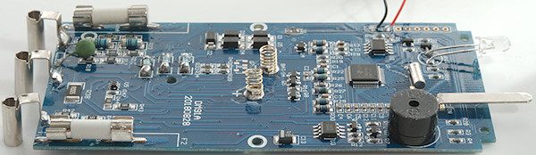
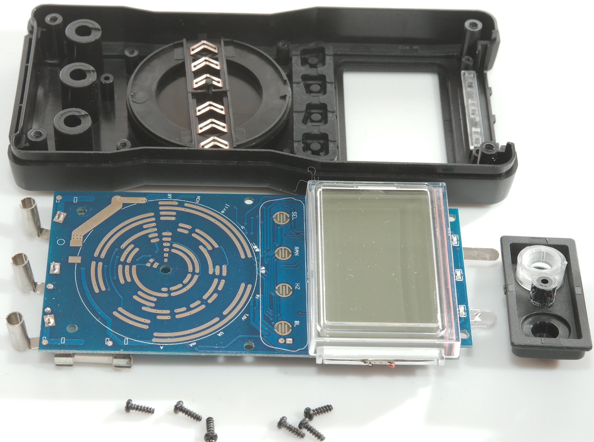
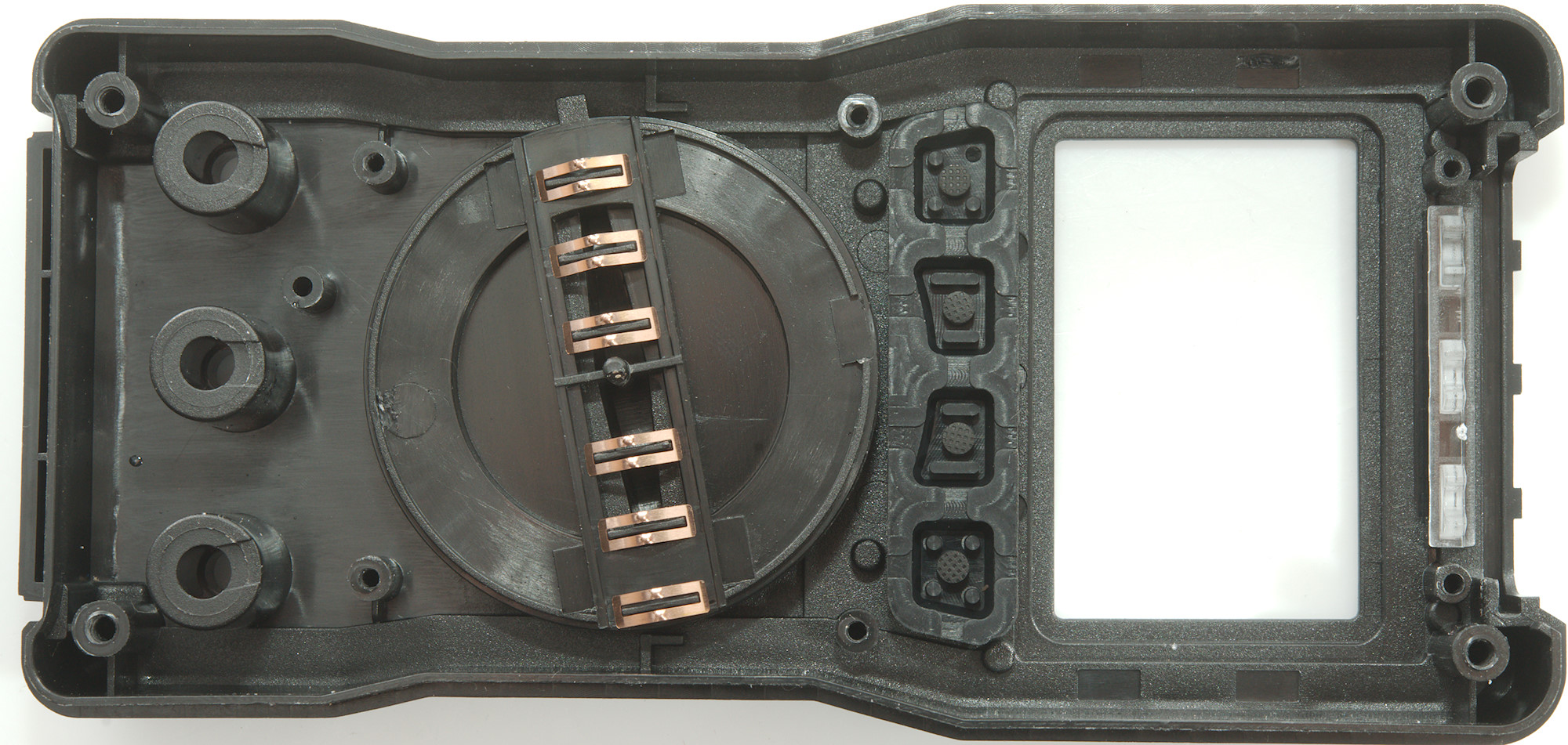
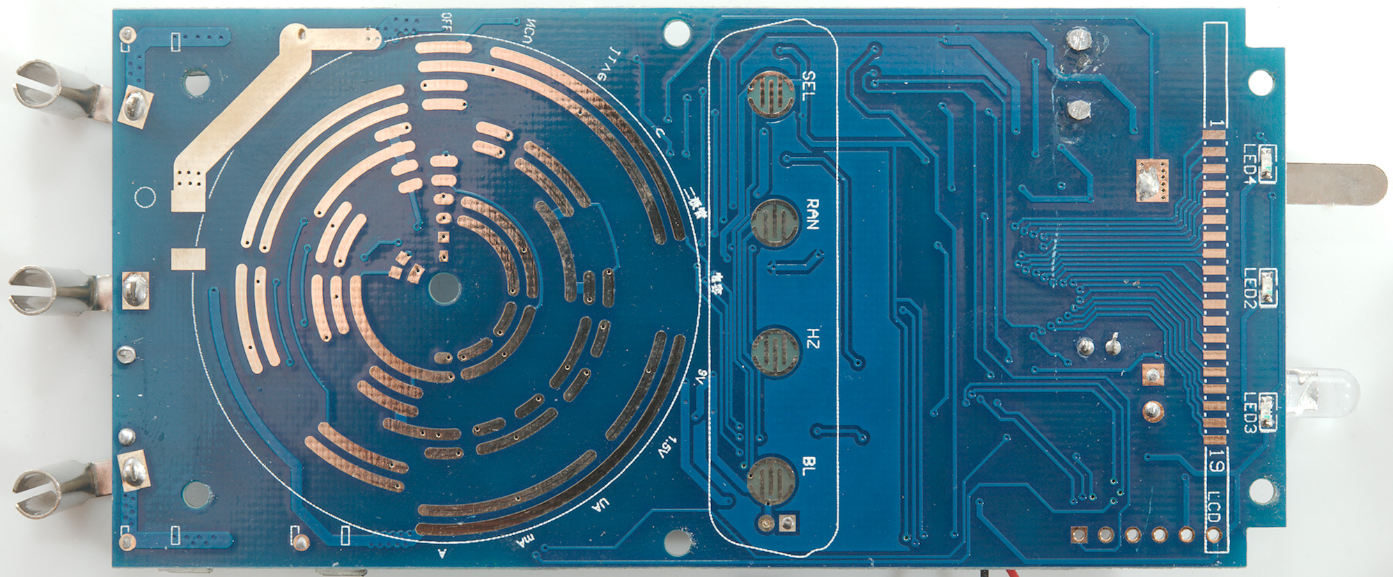
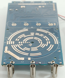
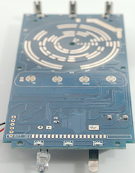
On this side is all the pads for switches and zebra stribe and the 3 leds.
Conclusion
As usual CAT rating is overstated with 250V fuses and a single PTC it will not handle CAT III 600V.
The meter has a good collection of ranges, but there is some ranges and functions missing, what you get instead is a battery tester and a small flashlight.
For normal around the house and hobby it is fairly good, but I do not believe the 1.5V battery range will handle much overload voltage.
Notes
How do I review a DMM
More DMM reviews