DMM Mustool X3
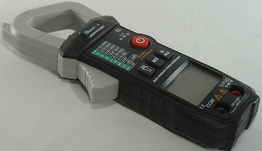
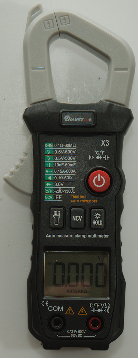
A clamp meter from Mustool that can only measure AC current.
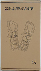
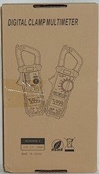
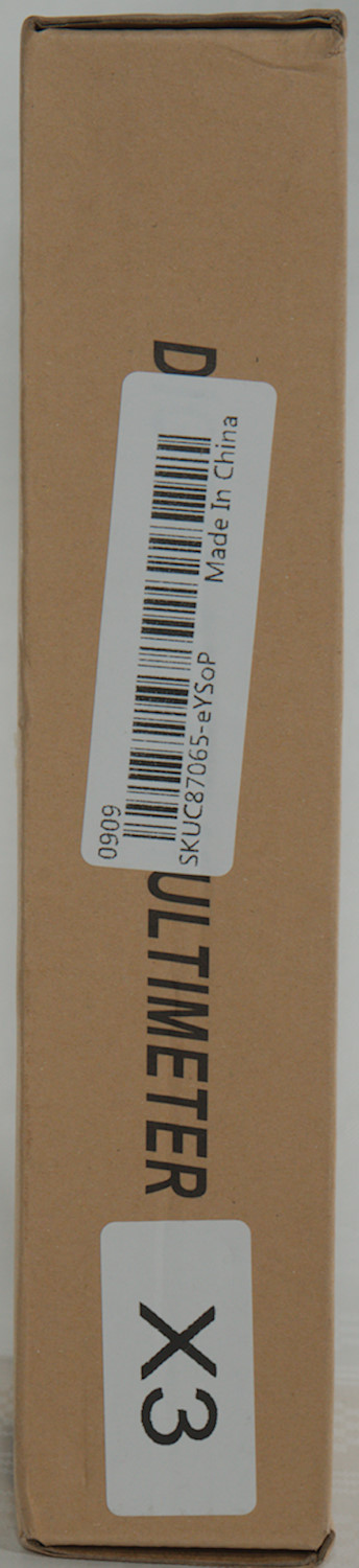
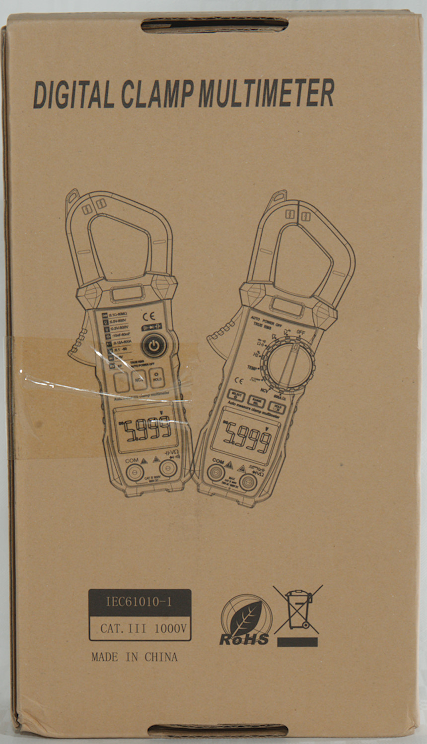
I got the meter in a generic clamp meter brown cardboard box with very little information on.
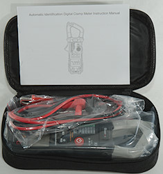
Inside the box was a pouch with everything in it, except the manual that did not fit in the pouch.
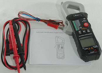
It included the DMM, a pair of probes, a thermocoupler and a manual.
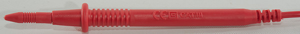
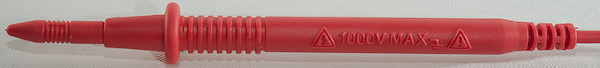
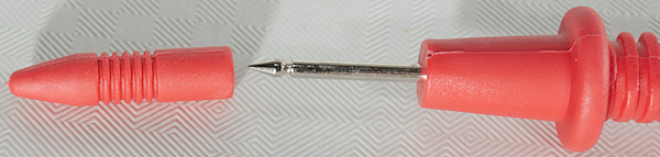
The probes are unbranded and marked for 1000V CAT III, but they do not have the partial tip cover.
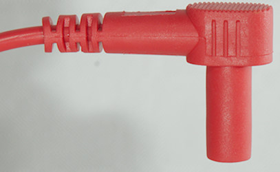
The shrouded plug is the slightly short variety.
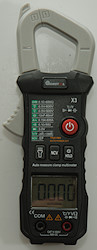
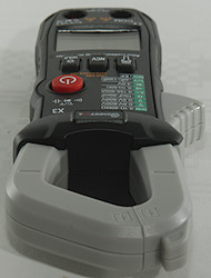
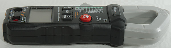
Flashlight is at the bottom of the meter, not the best position for a clamp meter.
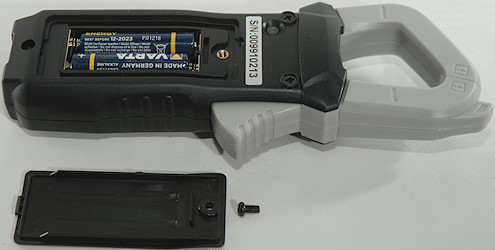
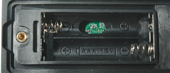
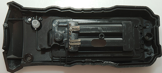
There is access to the electronic inside the battery box, but it do not look like calibration terminals (Maybe on another model).
Display
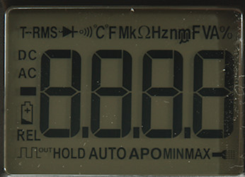
The above picture shows all the segments on the display, not all are used.
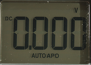
Typical display during usage, it will show the number and what measurement is selected.
Meter is in auto mode, where it will automatic change to current, voltage or ohm.
In NCV mode it shows bars depending on field strength, but it is not very sensitive, a live mains wire (230VAC) touching the clamp only got me one bar.
Functions
The list of functions do fully not match the sequence they are selected in.
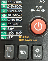
Buttons:
 : Change mode: Auto/VDC/VAC/Continuity/Diode/Capacity/Celsius/Fahrenheit, hold down to turn on off.
 : Turn flashlight on/off.
- NCV: Hold down to activate non contact voltage detection
- HOLD: Press to freeze display, hold down to turn background light on.
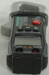
Input
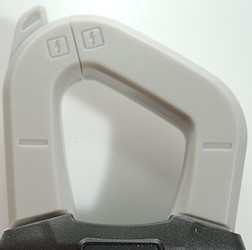
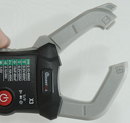
Clamp, used for AC current measurement.
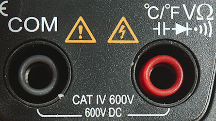
These terminals are used for Voltage, ohm, diode, continuity and temperature.
- COM: The common terminal
- xxx: The positive terminal.
Measurements
- Volt and frequency
- 1 VAC is 5% down at 2.1kHz (RMS will not work at the frequency).
- Input impedance is 820kOhm on DC and AC
- Initial range selection is a auto mode with ohm, continuity, volt DC/AC and ampere AC.
- Auto will show VAC from about 0.47V and VDC from about 0.45V
- Overload protection 700VDC or 500VAC peak
- Current
- Ampere range will kick in when measuring above 0.10A (Display shows 0.15A, but will drop)
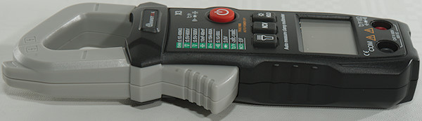
- Clamp can handle about ø27mm
- Ohm, Continuity, diode and capacitance
- Ohm needs about 1s to measure 100ohm (This is very fast for an auto ranging meter)
- Ohm is 0.4V open and 0.15mA shorted
- Continuity in auto mode is very slow (About 1.2s).
- Continuity in continuity mode is very fast (About 10ms).
- Continuity beeps when resistance is below 50ohm (Both modes).
- Continuity is 0.6V open and 0.33mA shorted
- Diode range uses 3.2V, max. display is 3.000V at 0.07mA, max. current is 1.0mA shorted
- 10uF takes about 6.5 seconds to measure.
- 11000uF takes about 13 seconds to measure.
- 70000uF takes about 15 seconds to measure.
- Overload protection 700VDC or 500VAC peak
- Miscellaneous
- Current consumption of meter is from 1.5mA to 3.5mA in continuity (11mA with backlight, 11mA with flashlight and 16mA with both).
- Meter works down to 2.2V where it turns off, battery symbol shows at 2.4V.
- Reading is stable until meter turns off
- Backlight fades with voltage and works down to where meter turns off.
- Flashlight fades with voltage and works down to where meter turns off.
- The meter usual need a couple of display update to reach the final value.
- Viewing angle is good.
- Display updates around 3 times/sec
- Backlight will automatic turn off in about 15 seconds.
- Flashlight will not automatic turn off, but turns off with the meter.
- Will automatic turn power off in about 15 minutes.
- Standard probes cannot be pushed fully down.
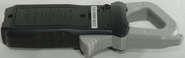
- Weight is 194g without accessories, but with batteries.
- Size is 179 x 67 x 33mm
- Probes
- Probe resistance 48mOhm for one.
- Probe wire is fairly soft and 74cm long.
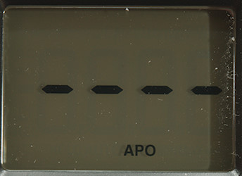
Auto range pulsing while searching for resistance and checking for voltages.
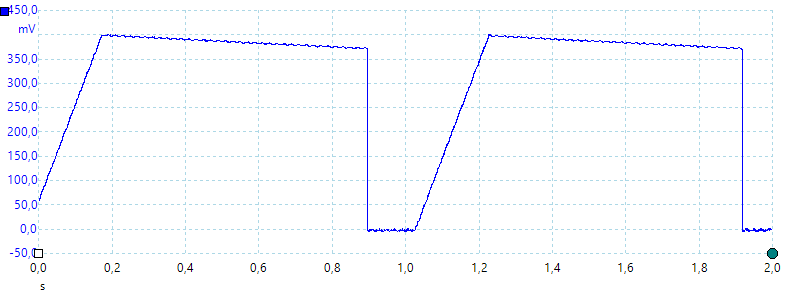
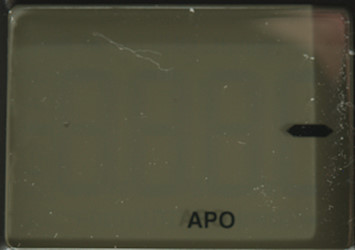
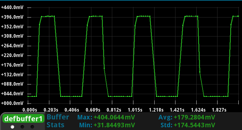
Capacity waveform while measuring 1uF
Meter is permanent in Low-Z mode.
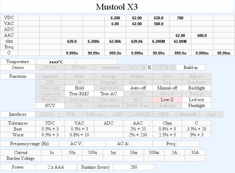
Specification in manual are a mix between clamp meter and ordinary current meter and resolution includes an extra digit.
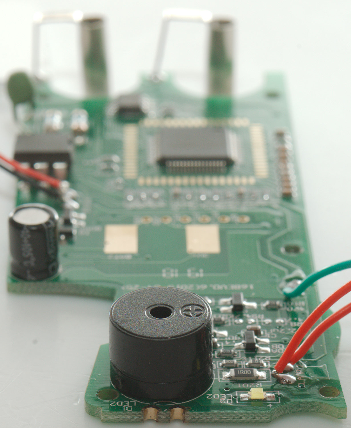
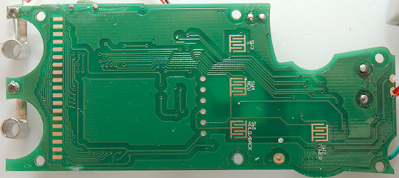
Tear down
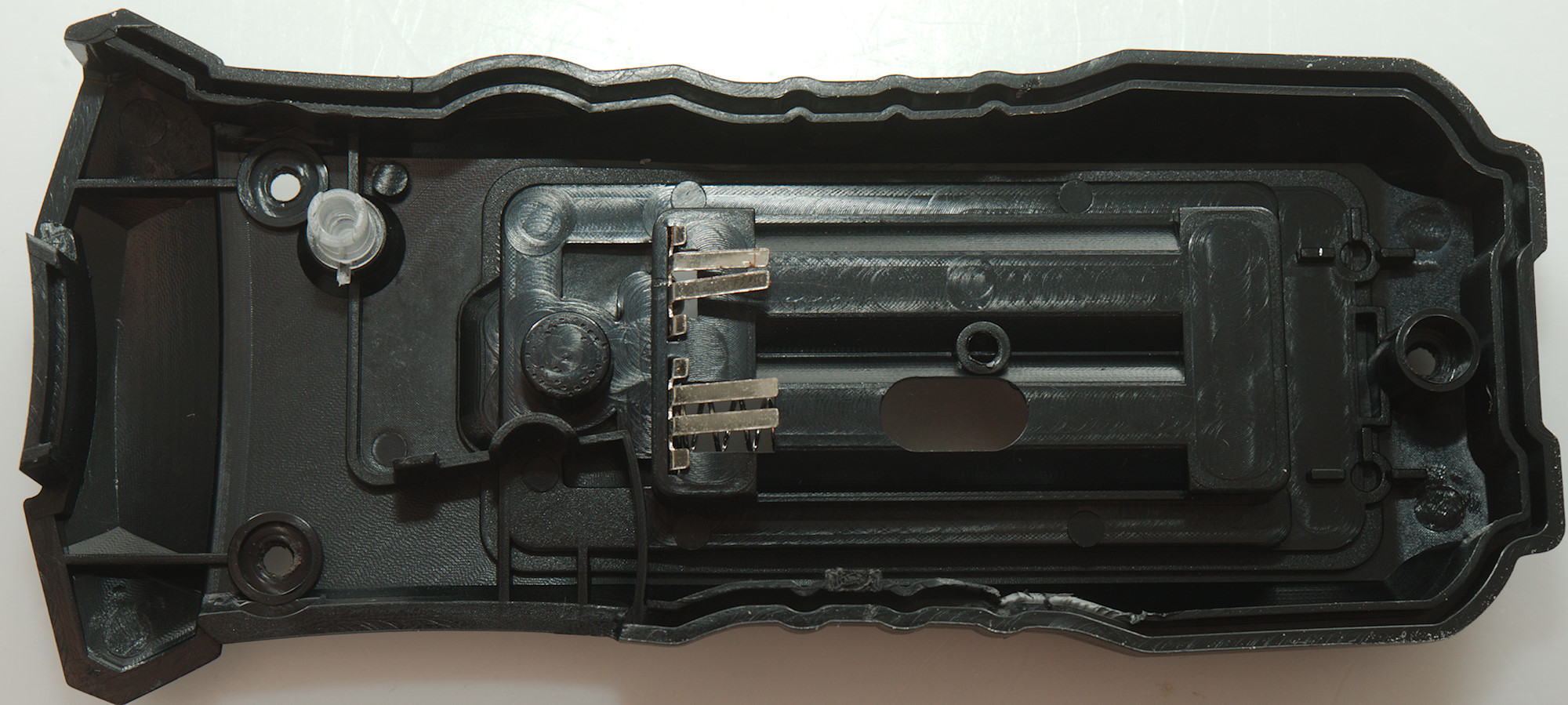
I had to remove 3 screws to open the meter.
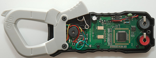
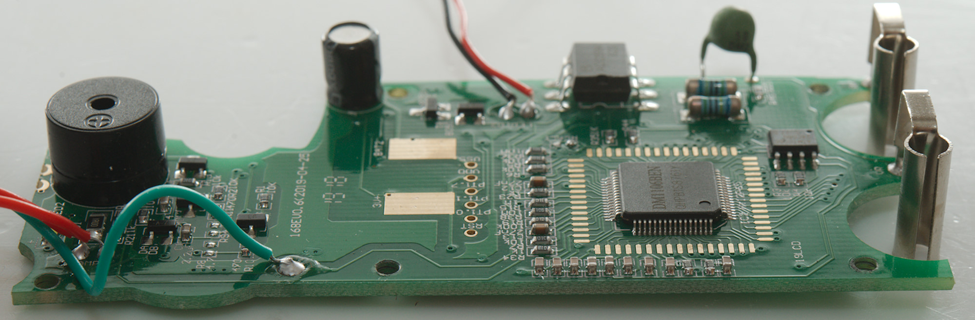
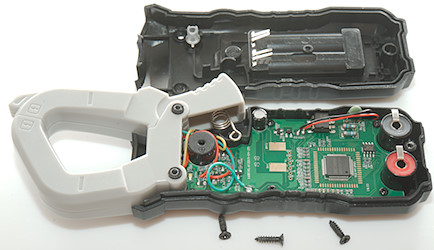
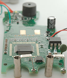
Circuit board is shaped to fit this enclosure, there is even a bump to match the enclosure opposite the clamp open handle.

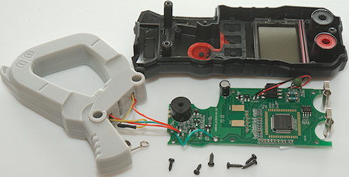
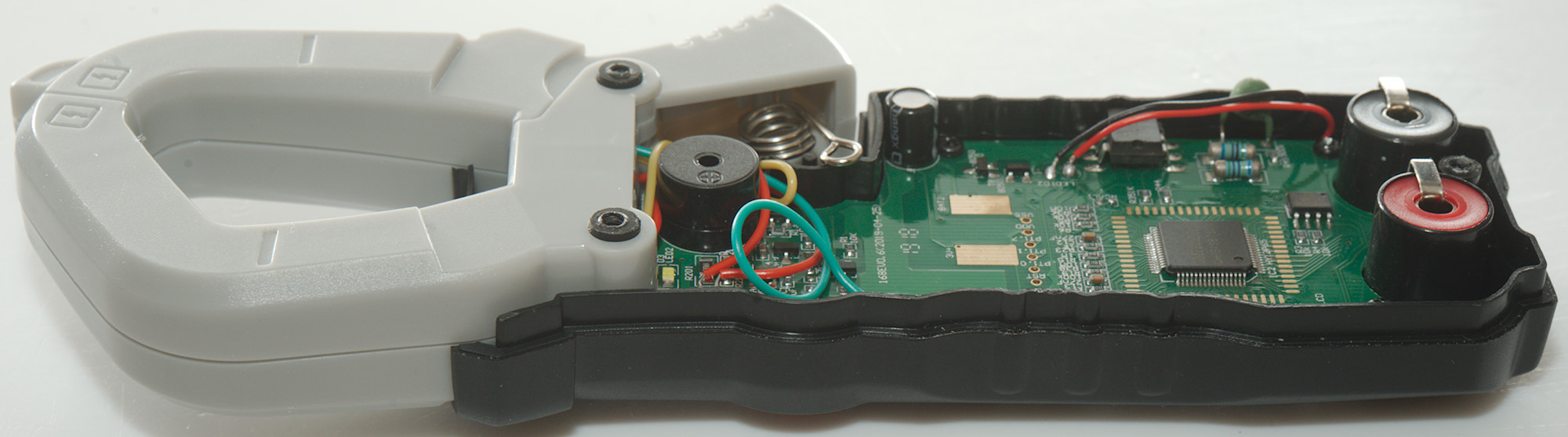
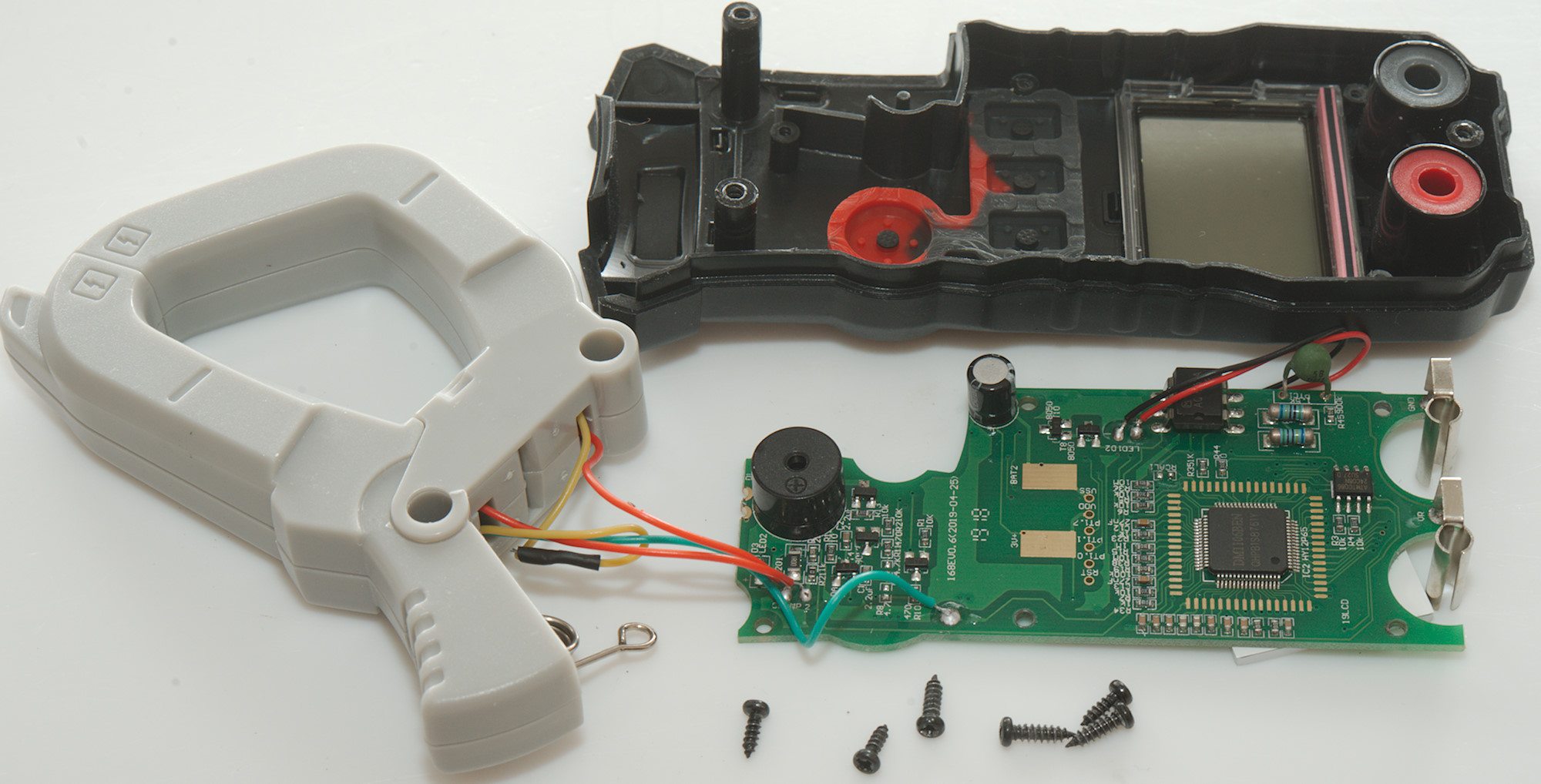
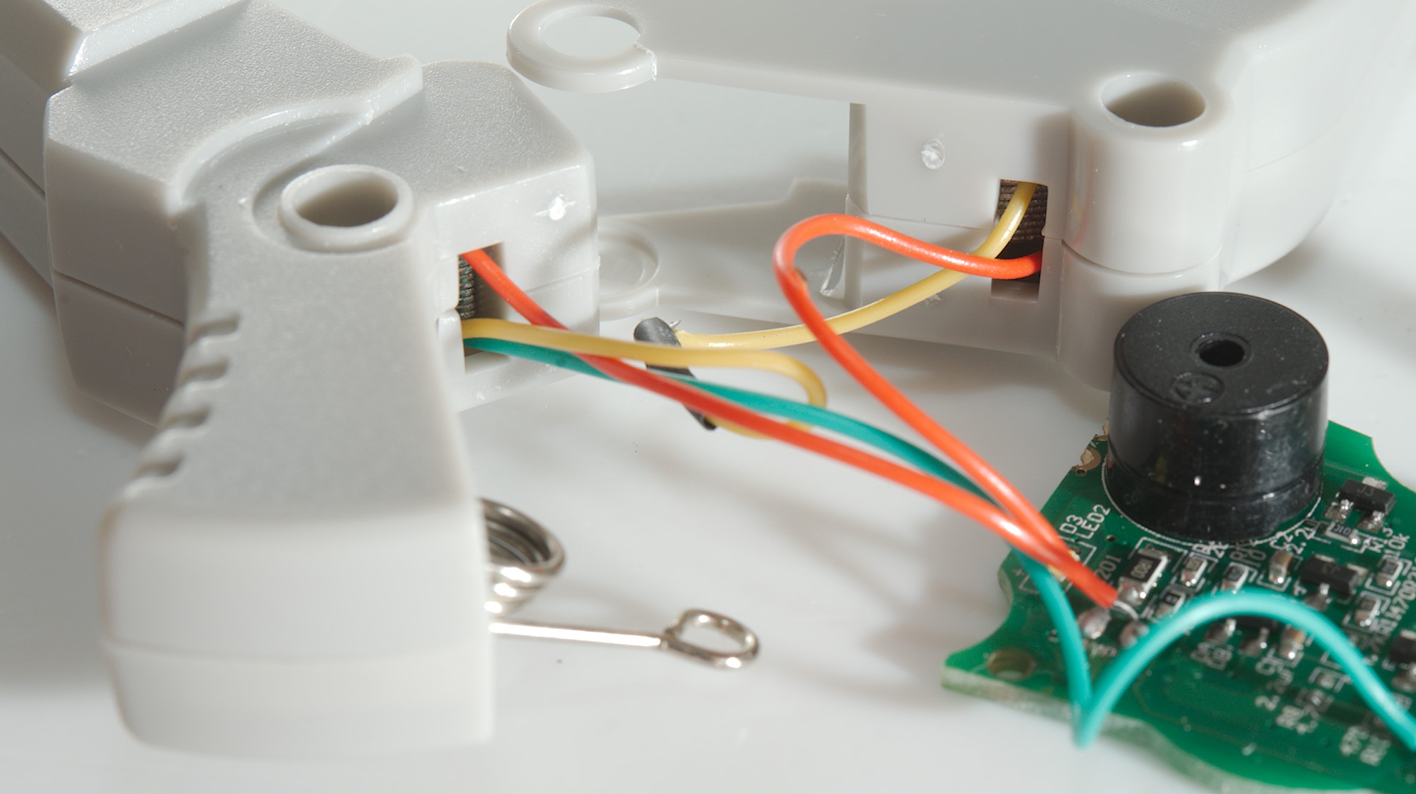
I had to remove 6 screw more to the get circuit board out, the clamp could just be pulled out.

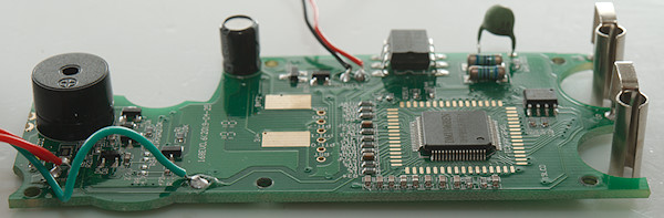
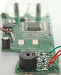
There is five wires into the clamp, two wires for a coil in each part and a wire for NCV.
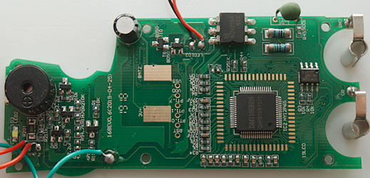
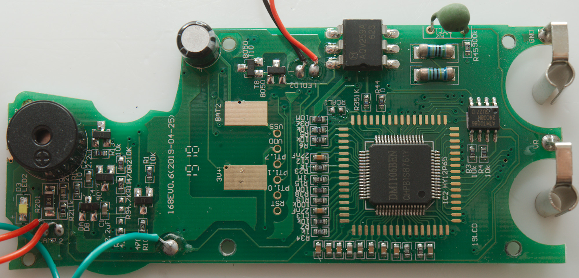
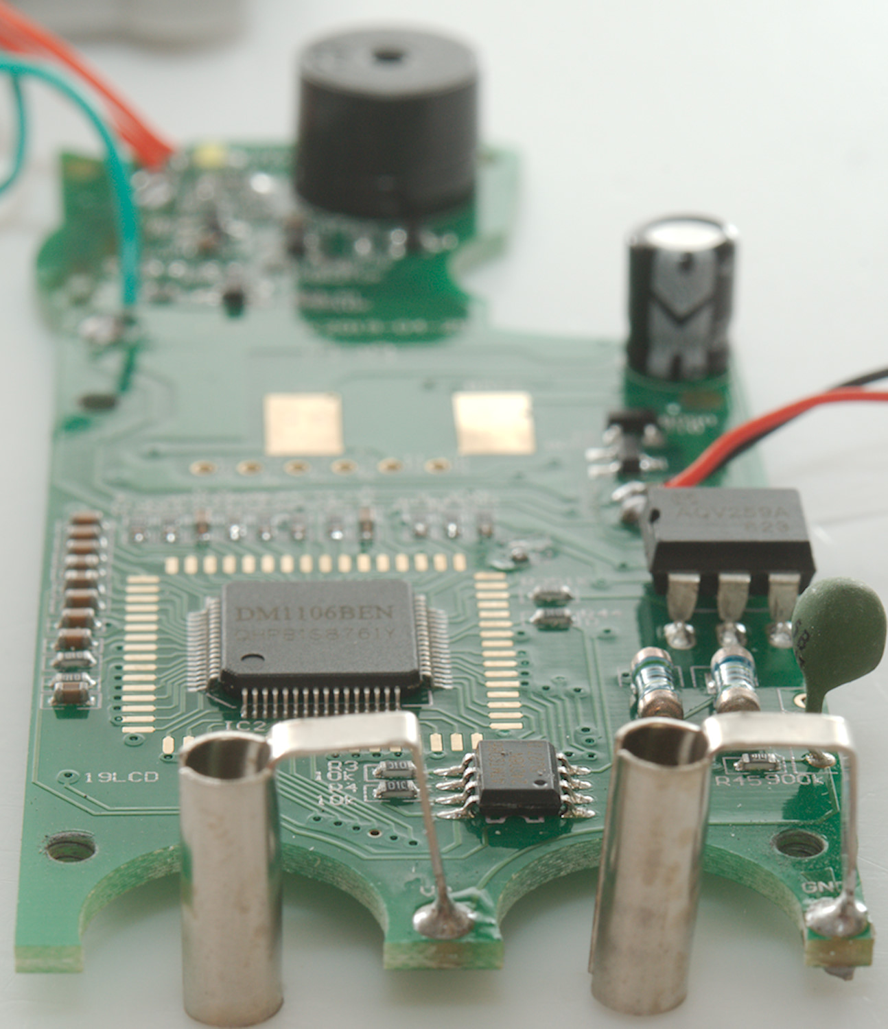
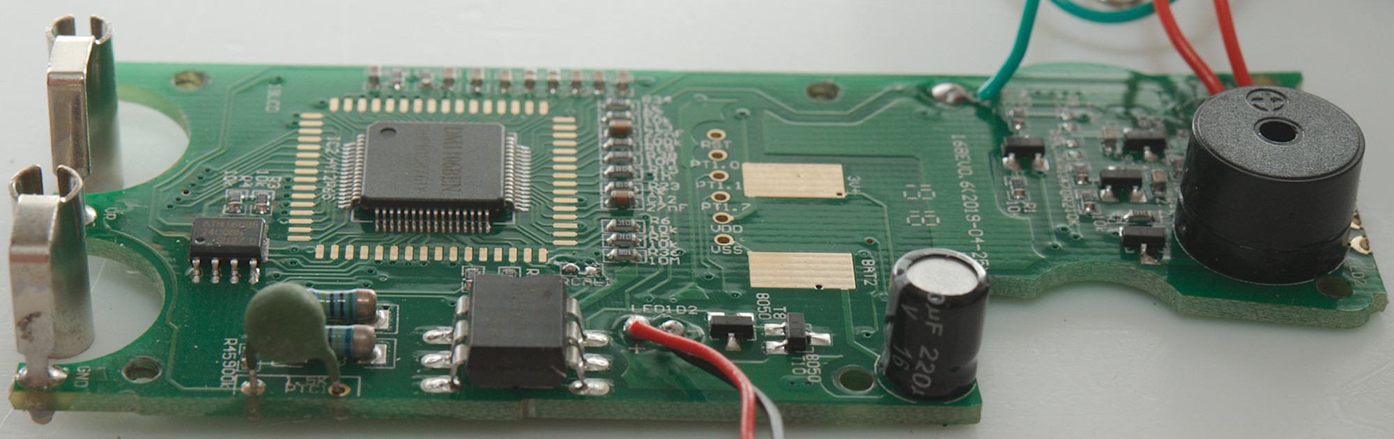
The input has the usually 3 paths with 10Mohm (Two MELF resistors), 1Mohm (910kOhm more exact: A small SMD resistor) and a PTC. The PTC goes to a electronic relay (AQV259A: 1000V relay) and then to a transistor pair for protection (T5 & T10) and from there through a resistor (R23: 1kOhm) into the multimeter IC. The more exiting path is the 1Mohm path, it goes directly to a pin on the multimeter IC and limits in the input impedance because the chips protection will divert any voltage above a few volt.
The multimeter chip (IC2: DMM1106BEN, but marked as HY12P65 on circuit board) has a EEPROM (24C08) to store calibration in.
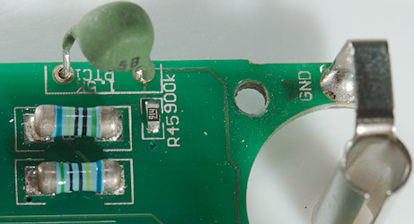
A closeup of the offending input resistor (R45).

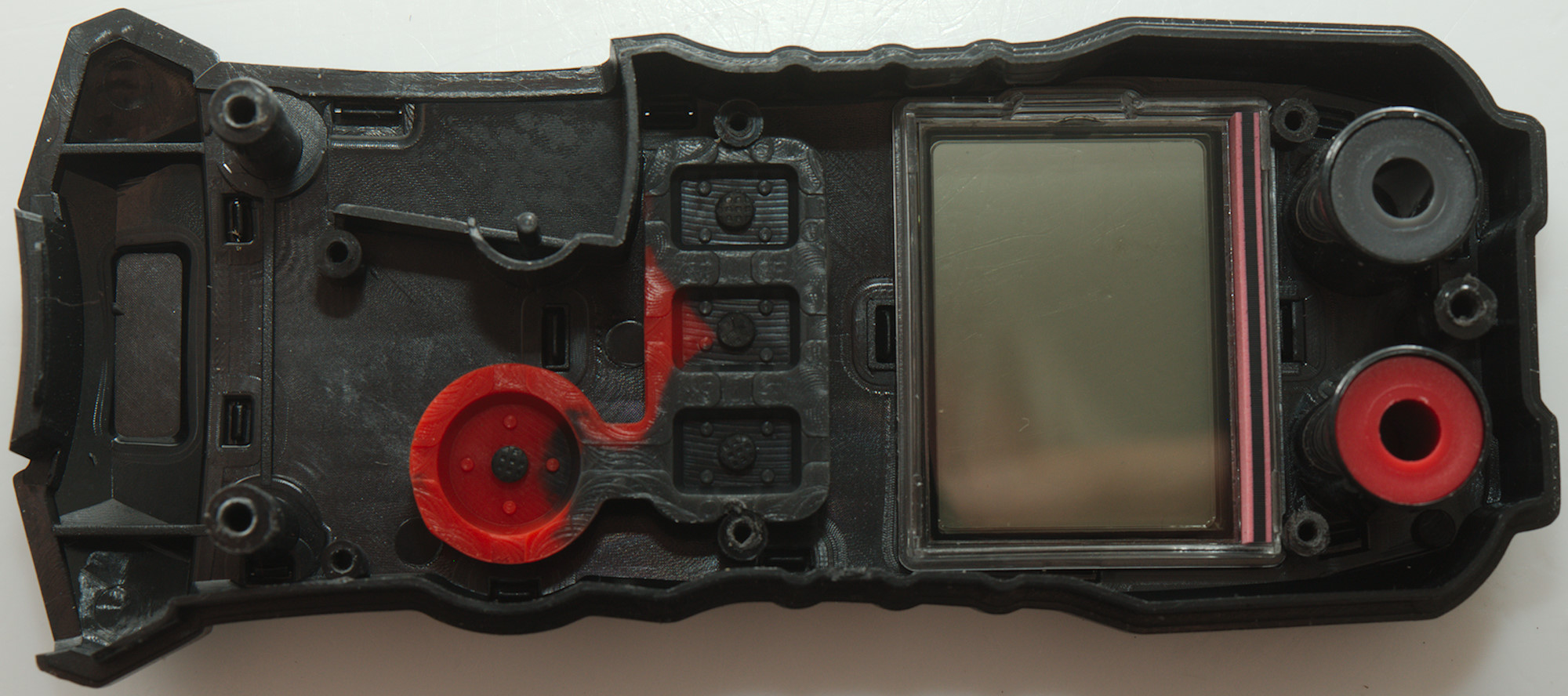
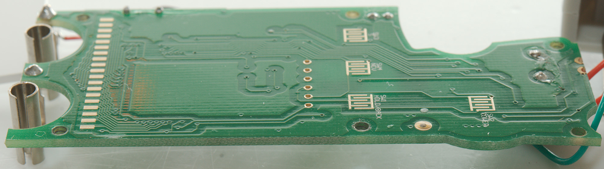
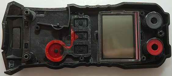
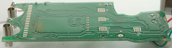
This side has the pads for the switches and for the LCD display, nothing else.
Conclusion
With no current input terminals the meter is safer, but letting a small SMD resistor handle the full input voltage is not safe when getting into 100's of volts. Calling a meter CAT ... 600V with a 500VAC limit is very wrong.
The meter is a AC clamp meter and with current ranges up to 600AAC, the main mode when using input terminations is automatic with voltage and resistance, using the red button there is also capacity and temperature.
It is not a bad meter after a ordinary mains outlet, but not for anything with higher voltage or current. The clamp can be used on higher current, but do not try to measure on the input terminals. The permanent "low" input impedance means that it is not very good for electronic.
Notes
The multimeter was supplied by banggood.com for review.
How do I review a DMM
More DMM reviews