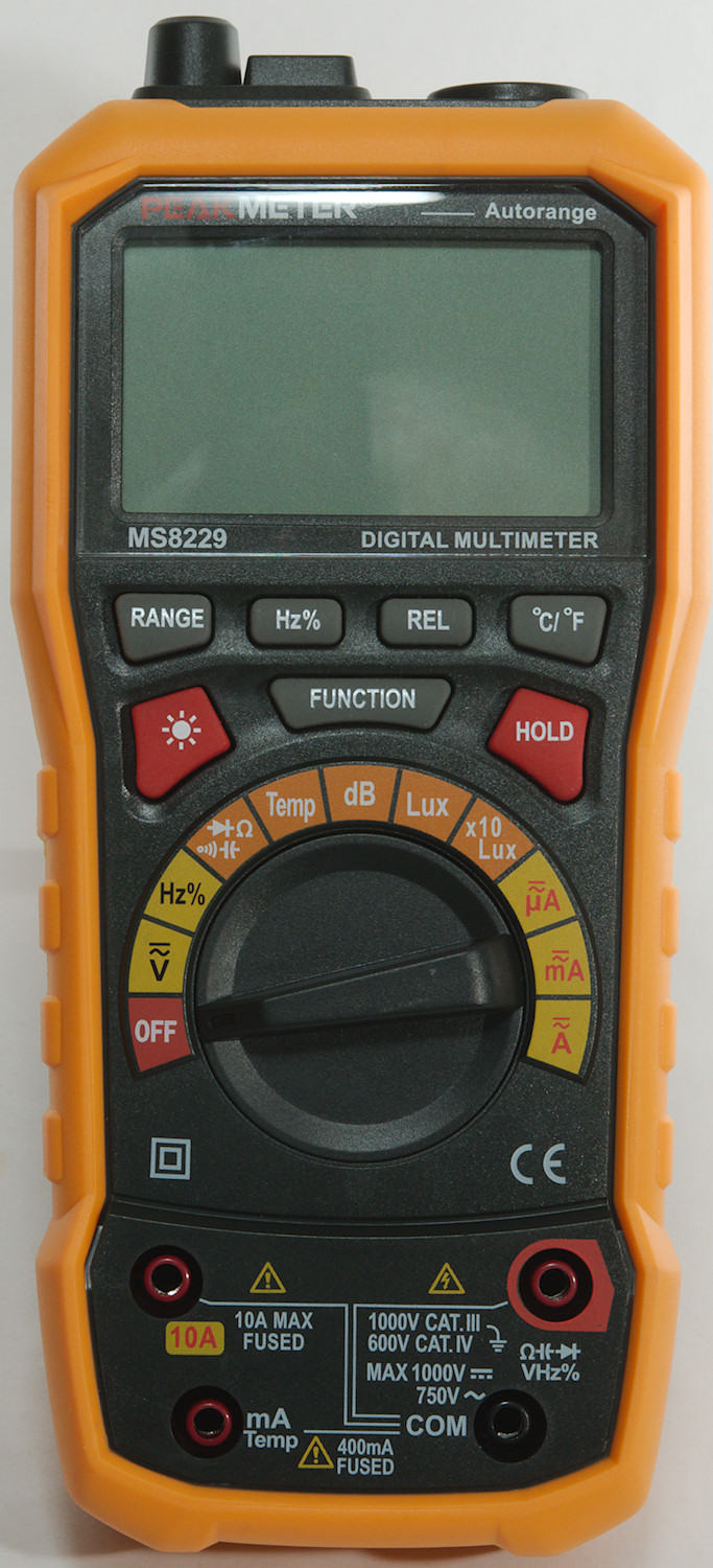
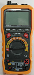
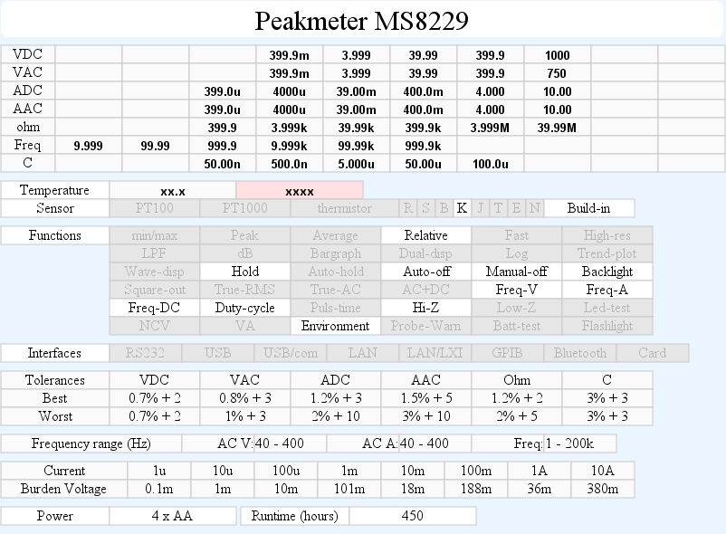
DMM Peakmeter MS8229
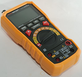
This is a cheap DMM with all common function and some environment functions.
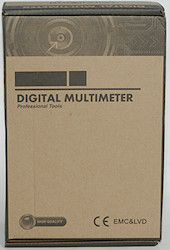
It arrived in a generic DMM box with no information on it.
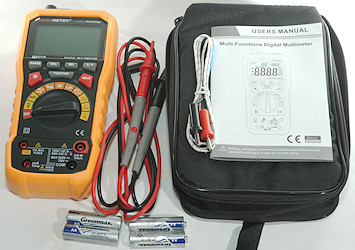
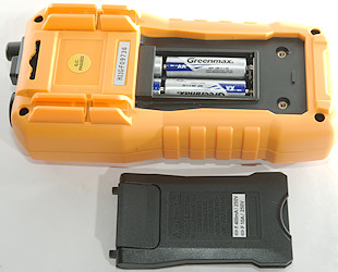
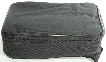
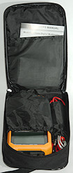
It included the DMM, a pair of probes, a thermocoupler, batteries, a bag and a manual.
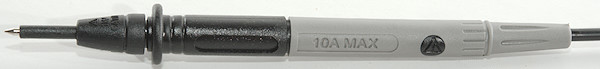
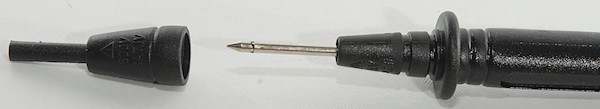
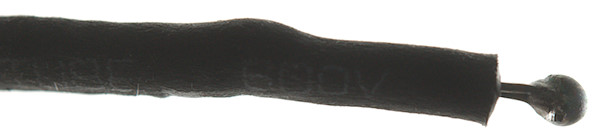
The probes has removable tip covers. The CAT rating is marked on the tip and will change when the cover is removed.
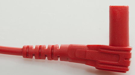
The plug is fully shrouded and a bit shorter than standard size.
The meter includes a cheap thermocoupler.
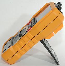
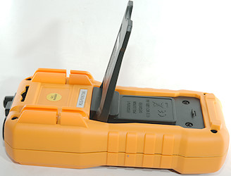
The tilting bale is stable enough to use the switch and buttons.
The range switch has very loud clicks, this can avoided by turning it carefully.
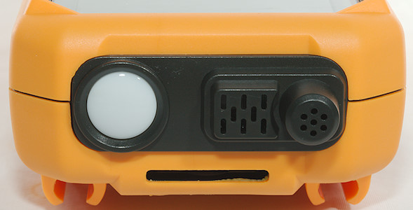
The environment sensors.
Display
The meter do not show all segments during power on.
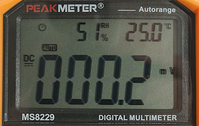
Typical display during usage, it will show the number and what measurement is selected.
The display will always show humidity and ambient temperature, but they need a few second to initialize when powering on.
Functions
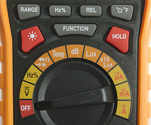
Buttons:
- Range: Will disable auto range and change range, hold down to activate auto range again.
- Hz %: Shows frequency and duty cycle in V and A ranges, changes to duty cycle in Hz range.
- Rel: Shows values relative to current value, will also select manual range. Press again to disable.
- °C/°F: Select between Celcius and Farnheit, holding this button down during power on will disable auto power off.
 : Turn background light on.
- Function: Select the secondary ranges (VAC AAC, continuity, diode, capacitance).
- Hold: Freezes the display, press again to release.
Rotary switch:
- Off: Meter is turned off
- V: Voltage DC and AC, use FUNCTION to select AC and use manual range to select mVAC
- Hz %: Frequency and duty cycle, for high bandwidth this selection must be used, it is only for low voltage.
 : Ohm, Diode, continuity and capacitance range, use SELECT to change between them.
- Temp: Temperature with thermocoupler, this will be shown on the main display and will not affect readout of ambient temperature.
- dB: Sound pressure.
- Lux: Brightness
- x10Lux: Brightness, higher range. The display has a small x10 indication to show this range is selected.
- uA: Current AC and DC, use SELECT to select AC
- mA: Current AC and DC, use SELECT to select AC
- A: Current AC and DC, use SELECT to select AC
Input
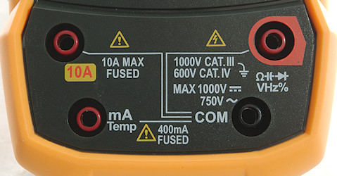
- 10A: High current, it can only withstand 10+ ampere for a short time (Fuse is 10A).
- mAuA: The lower current ranges and thermocoupler (temperature) input, the selector switch will change between two different shunts, it has a 400mA fuse.
- COM: The common terminal for all ranges.
- xxx: All other ranges.
Measurements
- Volt and frequency
- Frequency counter and duty cycle requires a zero crossing on AC and DC range, frequency input do not require it, but only works with positive signals.
- At 1Vrms frequency input range is from 0.4Hz to 700kHz
- Input impedance is 9.3 to 11Mohm on DC and AC
- mVDC range is high impedance (100Mohm) up to 1.5V where it drops to 10Mohm
- Duty cycle works from 10% to above 95% at 10kHz with 4Vpp, precision is within 3.6
- Duty cycle is slow to stabilize.
- 1 VAC is 5% down at 1.75kHz
- High DC voltage may block for AC readings and vice versa.
- Frequency input is 1-10Mohm below 10V, above 10V it drops to 1.5kOhm
- Current
- mA range is protected with 0.4A/250V 6.3x32mm fuse
- A range is protected with 10A/250V 6.3x32mm fuse
- Ohm, Continuity, diode and capacitance
- Ohm needs about 2.8s to measure 100ohm
- Ohm is 0.42V open and 0.21mA shorted
- Continuity is moderate in speed (About 60ms).
- Continuity beeps when resistance is below 44ohm (There is some noise for a few ohms more).
- Continuity is 0.44V open and 0.21mA shorted
- Diode range uses 1.5V, max. display is 0.999V at 0.2mA, max. current is 0.64mA shorted
- 100uF takes about 16 seconds to measure.
- 10uF takes about 3.2 seconds to measure.
- Miscellaneous
- Sound meter do not follow a A or C curve and readings will be too low at 1000Hz and above
- Light meter is fairly precise with incandescent, but is not filtered correctly.
- Meter will often reset when turning the switch, it will reset the display to Celcius.
- Current consumption of meter is 4 to 5mA (15mA with backlight)
- Meter turns off at 3.8V on battery, battery symbol show at 4.8V.
- Reading will change slightly with battery voltage: 2 count on a 3.0V reading from 6V to 4.8V, below 4.8V %RH will increase slowly.
- Backlight brightness will vary with voltage, but is works down to the meter turns off.
- The meter usual need a couple of display update to reach the final value and may show a too high value during that time.
- Viewing angle is fairly good, except from the top
- Display updates around 3 times/sec
- Backlight will automatic turn off in about 8 seconds.
- Will automatic turn power off in about 10 minutes.
- Standard probes fits in sockets.
- Weight is 422g without accessories, but with rubber sleeve and batteries.
- Size is 192 x 93 x 55mm with rubber sleeve.
- Probes
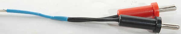
- Probe resistance 43mOhm for one.
- Probe wire is soft and 100cm long.
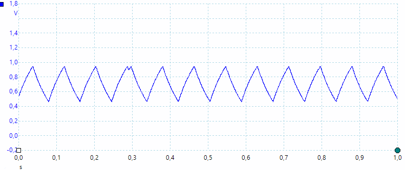
A look at the capacitance measurement waveform.
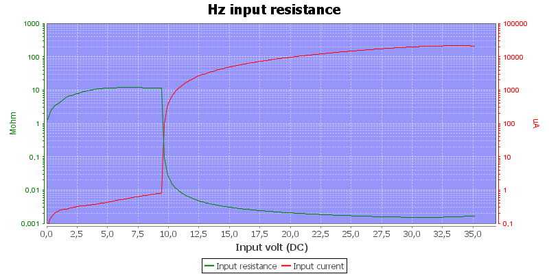
Frequency input resistance.
There is a 5° offset with thermocoupler when it is at zero.
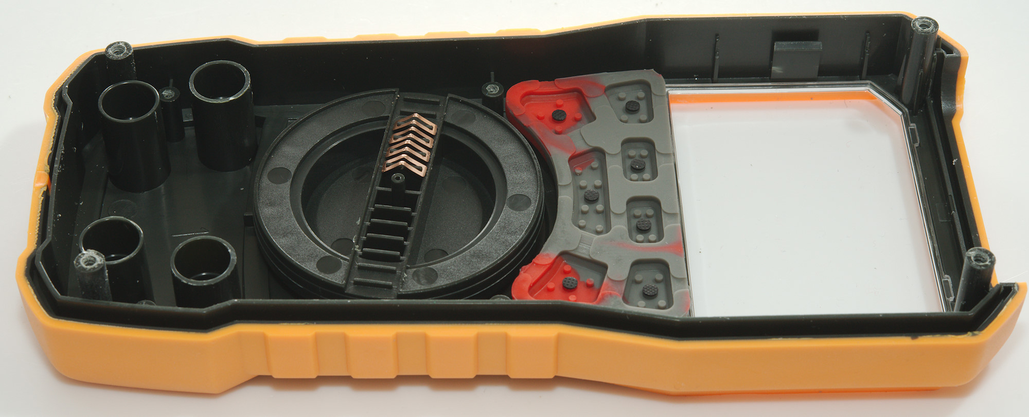
Tear down
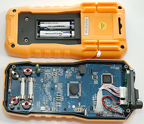
Four screws and the back could be removed.
The circuit board is shaped to use the box fairly well. There is four screws holding the circuit board and 3 screws holding the display.
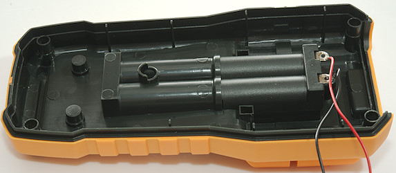
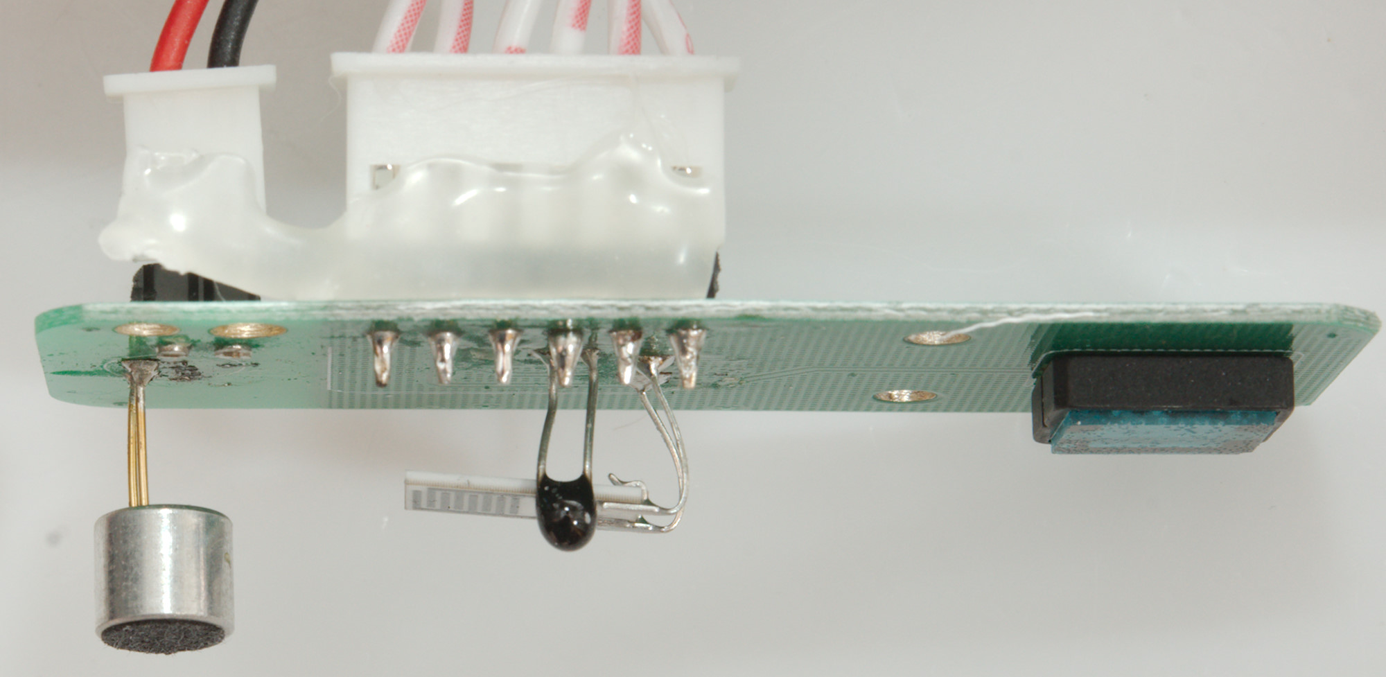
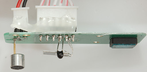
The sensors on the front uses two cables, one for lux, temperature and humidity and another for sound.
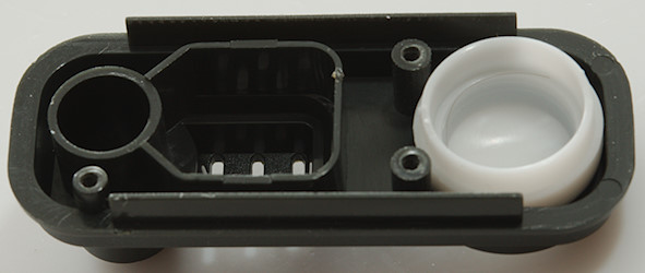
The top of the meter with holes for the sensors.
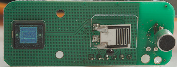
All four sensors, a photo diode, a humidity sensitive resistor, a temperature sensitive resistors and a microphone.
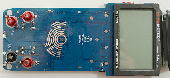
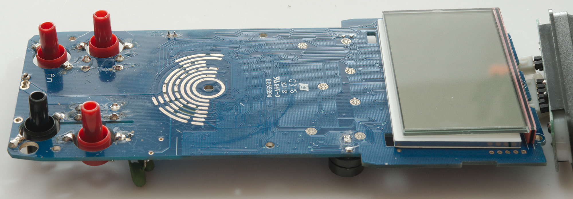
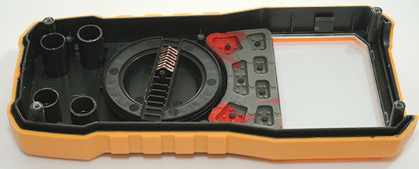
On this side of the circuit board is the switches and the lcd display.
There is nothing under the lcd display, except the backlight module.
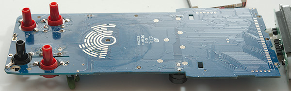

The white block is the backlight module, the pink part is the zebra stribe that connects the display to the circuit board.
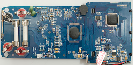
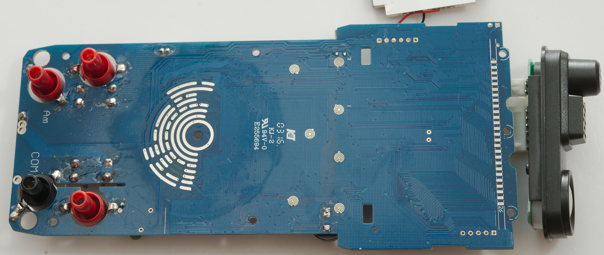
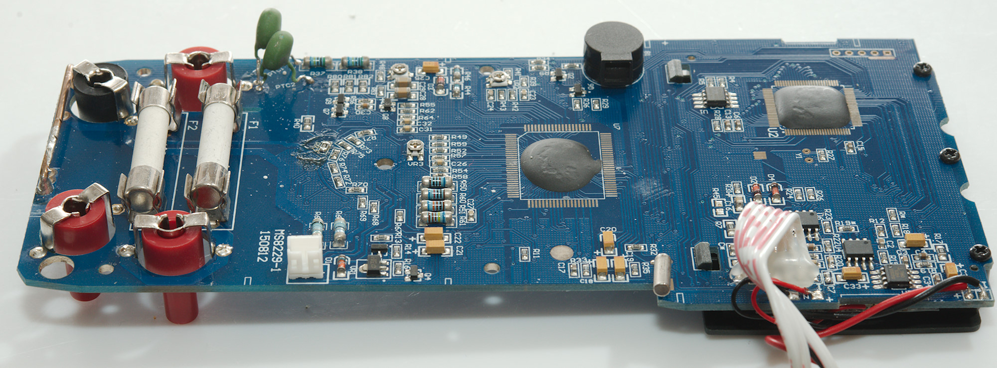
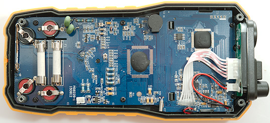
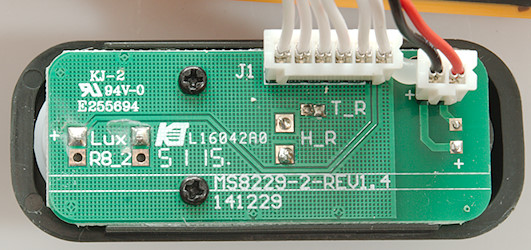
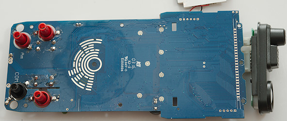
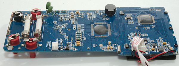
R63 is the 99ohm uA shunt and R66 is the 0.99ohm mA shunt, the chip near the resistors (VR1: 7530-1) is a 3 volt regulator. The 10A shunt is the wire at the bottom. The fuses are rated for 1000V and are the long type. But I am missing protection for the current sense resistor, this will usual be a couple of diodes.
At the voltage input is two PTC's one going to a 10Mohm input (R37+R38: 2x5Mohm) and on going to a 150Mohm input (R80, R81, R82: 3x47M). The transistors Q7 and Q9 looks like input protection. There is no MOV's to limit the voltage to the range switch.
The meter has two main chips: U7 is the DMM frontend and U2 is the processor, U1 is probably a EEPROM, the 3 trimpots on the circuit board is not enough to trim all the ranges. The handling of the environment sensors are U4, U5 and U6, all placed where the wires from the sensors are connected.
Conclusion
As usual I doubt the CAT rating, this meter do have some protection, but not enough. The environment sensors can be used, but sound is very bad and light is probably about the same as a cheap lux meter, except it only has two ranges.
The DMM functions are fairly standard, as usual the high mA range has a high burden voltage.
Notes
How do I review a DMM
More DMM reviews